ⓒ J. IEMEK 2013 Dec.: 8(6) 329-337 ISSN : 1975-5066
http://dx.doi.org/10.14372/IEMEK.2013.8.6.329
Is the Store-and-Forward Delivery Still the Best in Ad Hoc Networks?
Jiwon Park, Sangman Moh
*Abstract: In multihop routed ad hoc networks, the conventional store-and-forward delivery has been used. However, we may ask a question: “Is the store-and-forward delivery still the best?”
This paper presents a pipeline-through MAC (PT-MAC) protocol for ad hoc networks, in which nodes have two 3-channel interfaces in order to use limited radio resources efficiently and improve network performance. The proposed protocol reduces end-to-end delay significantly in multihop routed transmission by exploiting a novel pipeline-through technique rather than using the conventional store-and-forward. This results in improved network performance without increasing control overhead. Our extensive performance study shows that the proposed PT-MAC shows 20-40 percent shorter end-to-end delay and 25-55 percent better goodput compared to the IEEE 802.11 DCF with two 3-channel interfaces.
Keywords: Ad hoc network, MAC, Multihop routed transmission, Pipeline-through technique, Goodput.
*Corresponding author ([email protected]) Received: 9 July 2013, Accepted: 4 Sep. 2013.
J. Park: Sunggwang Inc.
S. Moh: Chosun University
※ A preliminary short version of this work was presented at the 1st International Conference on Smart Media and Applications, Aug. 2012 [10]. This research was supported in part by Basic Science Research Program through the National Research Foundation of Korea (NRF) funded by the Ministry of Education (NRF-2013R1A1A2011744).
I. Introduction
Mobile ad hoc networks are broadly used due to their advantages of easy deployment and low cost. To effectively exploit bandwidth-constrained radio resources, a well-designed MAC protocol is highly required [1, 2]. In the IEEE 802.11 standard [3], multiple data rates are supported at the physical layer and one of them can be chosen according to channel state. For example, a high data rate is used in case of high SNR (Signal-to-Noise Ratio); on the contrary, a low
data rate is used if SNR is low. For example, 6, 9, 12, …, 54 Mbps are supported in 802.11a [4] and 1, 2, 5.5, and 11 Mbps in 802.11b [5].
In this paper, the terms packet and frame are used interchangeably.
To support the functionality of multiple data rates, various protocols have been proposed.
Among those protocols, the ones that recognize channel state at the network layer can significantly improve the end-to-end transmission rate by selecting the optimal path based on the channel state [6, 7]. However, if path update gets slower and control overhead becomes higher, these protocols cannot react to dynamic channel conditions fast enough and thus cannot utilize high bandwidth. Some conventional approaches select a proper transmission rate, either by referring to the past transmission record or by using the channel state carried on CTS (Clear-To-Send) packet by the destination node [8, 9].
In this paper, a pipeline-through MAC
(PT-MAC) protocol for mobile ad hoc
networks, in which nodes have two 3-channel
interfaces to reduce end-to-end delay and
improve network performance, is proposed.
The proposed protocol reduces end-to-end delay in multihop routed transmission without increased negative effects by exploiting pipeline-through technique rather than conventional store-and-forward. In this paper, we present the detailed protocol design, the analysis of multihop delivery, and the extensive performance evaluation and comparison. A preliminary short version of this study was introduced in [10] but, in this paper, the protocol design and performance evaluation are significantly extended in terms of quality and quantity. According to our performance study, the proposed PT-MAC improves the network performance remarkably in terms of end-to-end delay and goodput (effective throughput). But, the control overhead is not increased in comparison to the existing protocols. As a matter of fact, 20-40 percent shorter end-to-end delay and 25-55 percent better goodput are observed in the extensive simulation.
The rest of this paper is organized as follows: Some related works are reviewed in brief in the following section. The principles and operation modes of PT-MAC are presented in Section III. In Section IV, multihop delay is mathematically analyzed. The performance of PT-MAC is extensively evaluated and compared to the conventional protocols in Section V. Finally, Section VI sums up the conclusion of this study.
Ⅱ. Related Works
The IEEE 802.11 standard supports both ad hoc networks and infrastructure networks [2], and the MAC protocol for ad hoc networks is competition-based DCF (Distributed Coordination Function). DCF defines the simple data transmission scheme and the RTS/CTS (Request To Send/Clear To Send) scheme.
According to the first approach, which is the basic approach, when there a data packet to
be sent, an arbitrary back-off value is defined;
sources nodes reduce the back-off value while the channel is idle; the source node that reaches 0 first gets to send the data packet;
and the destination node that receives the data packet returns acknowledgement (ACK) packet.
Once acknowledging the data transmission from the source node, its neighboring nodes set their NAV (Network Allocation Vector) to as much time as written on the duration field of the corresponding data packet, during which they do not send any data. The second is RTS/CTS approach, which uses CSMA/CA (Carrier Sense Multiple Access with Collision Avoidance) mode. When source node with data packet sends an RTS packet to destination node, the destination node returns to the source node CTS indicating whether it can receive the data packet or not. The source node sends the data packet to the destination node, and then the destination node returns ACK packet to the source node.
In the above-mentioned medium access, the
time frame between frames is called IFS
(InterFrame Space), and the node uses frames,
referring to the IFS-based medium. There are
four types of IFS: SIFS (Short IFS), PIFS (PCF
IFS), DIFS (DCF IFS), and EIFS (Extended IFS),
and they are used in order to provide wireless
medium with the priority level. SIFS is used
for sending frames with the highest priority
such as ACK frame, CTS frame, and polling
repl. It has the shorted inter-frame space and
thus has the highest priority. PIFS is used for
acquiring the priority for medium connection in
the contention section, and must be used for
the nodes that use PCFs. Nodes that use PCFs
can transmit contention-free traffic. DIFS is
used for transmitting data frames or
management frames by DCF-mode nodes, with
the lowest priority. When the node finishes
sending the frame and NAV is set to 0, it
must wait as long as DIFS. EIFS is used by
the physical layer on DCF to inform MAC
layer that MAC frame has not been received
correctly.
A wireless ad hoc network of self-organized autonomous nodes is characterized by high adaptability to dynamic change of network topology as it can be configured without infrastructures required for the traditional networks. Each node communicates with distant nodes by using multihop transmission through intermediate nodes. In the wireless ad hoc network, each node is a device with wireless communication capability. Typical nodes are laptop computers, handheld computers, PDAs, sensor devices, or embedded devices. In general, the wireless network indicates logical inter-node connection that is capable of half-duplex transmission and reception by an omni-directional antenna with specific transmission range.
As a wireless channel is time-varying and location-dependent due to path loss, shadowing and small-scale fading as well as interference, rate adaptation is a powerful way to overcome channel variations. The IEEE 802.11 standards incorporate physical-layer multi-rate capability.
However, they do not specify how to choose the data rate and, thus, some schemes to select the rate adaptively have been proposed.
The auto rate fallback (ARF) [8], the receiver based auto rate (RBAR) [9], and the opportunistic auto rate (OAR) [11] are the MAC protocols that utilize rate adaptation. As all three protocols take channel quality into consideration, low channel quality results in reduced performance. However, several routing protocols have enhanced end-to-end throughput or emerge efficiency based on channel quality [1, 6, 7, 12].
In terms of transmission rate control, the MAC layer can recognize and respond to channel state faster than the network layer.
rDCF (relay-enabled DCF) protocol, which enhanced the transmission rate using intermediate nodes at the MAC layer [13], introduced a packet relay mechanism to improve effective transmission rate for the links with low transmission rate in the wireless
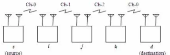
Fig. 1 Pipeline-though transmission via multiple nodes
ad hoc network. When the transmission rate between the sender and the receiver is low, a relay node is searched and used. In other words, a relay node receives data from the sender node and then forward data to the receiver node on the basis of the conventional store-and-forward. However, such store-and- forward incurs a longer transmission delay and a lower effective transmission rate in comparison to the pipeline-through MAC proposed in this paper. This will be shown in Sections VI and V.
Ⅲ. Pipeline-though MAC
In this section, a pipeline-through MAC (PT-MAC) protocol is proposed for wireless ad hoc networks composed of mobile nodes with two 3-channel radios.
Fig. 1 shows the pipeline-through
transmission via multiple nodes between source
and destination. The source node s sends data
packet to intermediate node i through one of
two wireless interfaces, using Channel 0
among three channels. As soon as the
intermediate node i receives the header of the
packet through one of two wireless interfaces,
it immediately sends the packet to intermediate
node j through the other remaining wireless
interface, using Channel 1, in a pipelined
fashion even though it does not receive the
whole packet. As soon as the intermediate
node j receives the header of the packet
through one of two wireless interfaces, it
immediately sends the packet to intermediate
node k through the other remaining wireless
interface, using Channel 2, in a pipelined
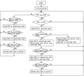
Fig. 2 Pipeline-though MAC operation at each node
fashion even though it does not receive the whole packet. The same pipeline-though transmission is carried out along with the routing path until the destination d receive the packet.
Channels on the path are allocated according to round-robin method. When the communication channel with upstream node is Channel c, Channel (c + 1) mod 3 is used as the communication channel for downstream node. Here, the channel number c is between 0 and 2, and the mod operator refers to modulo operation.
It should be noted that there may be many intermediate nodes between source and destination. If it is impossible for an intermediate node to send data packet right away to downstream node on the routing path, the intermediate node temporarily stores the packet and then sends it immediately when it becomes possible. Finally, the destination node receives the data packet through one of two wireless interfaces.
Fig. 2 shows a flow chart that shows pipeline-through medium access control at each node. In the beginning, the pipeline-through MAC device is reset for initialization. Then, packet buffer becomes
empty and two wireless interfaces enter standby mode for reception, during which the pipeline-through MAC device maintains its initialized state.
If RTS is received after initialization, the
data reception procedure is carried out as
shown in the center row of the flow chart in
Fig. 2. That is, each node checks whether the
RTS is meant to be received by it. If the RTS
is not meant for it, the node restores to
standby state to receive RTS. If the RTS is
meant for it, the node returns CTS to the
upstream node on the path from which RTS is
sent. Then, it checks if there is a downstream
node on the path. If there is no downstream
node, it means that the node is the destination
node and therefore it receives data from the
upstream node, returns ACK to the upstream
node, and then returns to standby state to
receive RTS. On the other hand, if there is a
downstream node, the node sends RTS to the
downstream node and receives data from the
upstream node. Afterwards, it checks whether
CTS is received normally from the downstream
node on the path with the predefined time. If
CTS is not received normally, the node returns
to standby state to receive RTS. Then, as
having to send the data received from the
upstream node to the downstream node, the
node attempts to resend the data through the
standby state to receive RTS and the medium
check stage for data transmission. On the
other hand, if CTS is received normally, the
node sends the data to the downstream node
on the path by pipeline-through and then
returns to ACK to the upstream node on the
path. Afterwards, the node checks whether
ACK is normally received from the downstream
node on the path within the predefined time. If
ACK is not received normally, the node returns
to standby state to receive RTS. Then, as
having to send the data received from the
upstream node to the downstream node, the
node attempts to resend the data through the
standby state to receive RTS and the medium
check stage for data transmission. On the
n T
PTT
BT
BOT
hT
sNumber of hops from source to destination Average per-hop pipeline-through delay Buffer delay in a node
Back-off delay Average per-hop delay
Average store-and-forward delay in a node Table 1. Notations for multihop delay analysis
other hand, if ACK is received normally, the node deletes the sent data from the buffer and then returns to standby state to receive RTS.
In case RTS is not received after initialization, if there is data to send, the data transmission procedure is carried out as shown in the left-hand row of the flow chart in Fig.
2. This step by step operation in sequence is borrowed from the IEEE 802.11 standard and performed in a pipelined fashion.
Ⅳ. Multihop Delay Analysis
For multihop transmission, it is assumed that packets are transmitted through n hops from the source node to the destination node.
Table 1 shows the notations used for analysis of end-to-end delay, in which Ts is considerably larger than T
B(T
B<< Ts).
The end-to-end delay in PT-MAC (T
PT-MAC) can be expressed as in Eq. (1), based on the flow chart of MAC operation in Fig. 2. Here, T
PTis inter-hop pipeline-through delay for n-hop packet transmission from source node to destination node, which as shown in Eq. (2) includes buffer delay, back-off time, RTS transmission time to start pipeline-through transmission to downstream node, and SIFS time. For the n-hop packet transmission from source node to destination node, T
PTin Eq. (2) is performed (n – 1) times, If Eq. (2) is applied to Eq. (1), the pipeline-through delay can be calculated as shown in Eq. (3).
On the other hand, delay time required for using IEEE 802.11 DCF (
) can be expressed as shown in Eq. (4). Here,
is average delay time between hops, which includes the processes of RTS, CTS, DATA, and ACK in the basic DCF, and
is average delay time occurring until transmission after storing. In n-hop packet transmission from source node to destination node,
happens times while
happens times. By substituting
in Eq. (4) by Eq. (5), the end-to-end delay required for the basic DCF can be calculated by Eq. (6)
Difference between T
DCFand T
PT-MACis shown in Eq. (7). It can be significantly reduced delay, as T
DATAand T
sare considerably large values.
V. Performance Evaluation
In this section, the performance of the proposed PT-MAC is evaluated via extensive simulation using ns-2 [14] and compared with the conventional approach.
1. Simulation Environment
In order to measure its performance, the proposed PT-MAC protocol was implemented on ns-2 simulator. The simulation parameters are shown in Table 2, and the variable simulation parameters are pause time and transmission rate. The simulation was carried out by varying one parameter while setting the other variable parameter to its default value. In each experiment, end-to-end delay, goodput and control overhead were measured.
To verify the effect of performance
Parameter Value
Number of nodes 50
Topology
dimension 300 × 1500 m
2Propagation
channel model Two-ray ground reflection Traffic source Constant bit rate (CBR) Number of sessions 6
Transmission rate 1, 2, 4, 8, 16 (default: 4 packets/sec)
Mobility model
Random waypoint model
- Pause time: 0, 20, 50, 100, 300, 600, 900 sec (default: 100 sec) - Speed: 0 to 5 m/sec Simulation time 900 sec
Routing protocol AODV
Table 2. Simulation parameters
improvement, not only the proposed PT-MAC but also the conventional IEEE 802.11 DCF protocols (DCF
s, DCF
m) implemented with one single-channel interface and two 3-channel interfaces were implemented.
2. Simulation Results and Discussion
In our performance study, the proposed PT-MAC protocol was compared with the conventional IEEE 802.11 DCF protocols (DCF
s, DCF
m) with one single-channel interface and two 3-channel interfaces.
Fig. 3 represents the end-to-end delay at various pause time and transmission rate. In Fig.
3(a), it is shown that, compared to DCF
swith one single-channel interface, DCF
mwith two 3-channel interface has 10-24% less end-to-end delay. Also, the use of PT-MAC protocol for packet relay in the intermediate node for packet relay has achieved 27-38%
reduction in the end-to-end packet transmission delay, in comparison to DCF
m. In Fig. 3(b), DCF
sshows the end-to-end delay of 121 ms when the transmission rate is 8 and 808 ms when it is 16, indicating that the end-to-end delay increases as the transmission rate increases. In comparison, DCF
mperforms better as the transmission rate increases. On the other hand, the end-to-end delay of PT-MAC is 26-44%
lower than that of DCF
m. In Fig. 3(b), based on the transmission rate of 4, it is slightly lowered
(a) Varying pause time
(b) Varying transmission rate Fig. 3 End-to-end delay
in the section with the transmission rate lower than 4. This can be explained as, if there is too little network traffic, the routing table is not updated frequent enough that more routing tables expire. However, in the section with the transmission rate higher than 4, network traffic increases, resulting in the increase in the end-to-end delay.
Fig. 4 represents the goodput at various pause time and transmission rate. The goodput in Fig. 4(a) is the application-level throughput.
Goodput refers to the transmission rate of effectively delivered packets in the end-to-end packet transmission, which does not include control packets and retransmitted data packets.
Since the end-to-end delay has been reduced
as shown in Fig. 3(a), the goodput of PT-MAC
in Fig. 4(a) shows 40-56% increase from that of
(a) Varying pause time
(b) Varying transmission rate Fig. 4 Goodput
DCF
m. The fact that graphs have flat shapes in general implies that varying the node mobility does not have much impact on MAC performance. In Fig. 4(b), PT-MAC has the goodput of 41-46% increase from that of DCF
m, due to its reduced end-to-end delay. Goodput also has the same tendency as end-to-end delay, that it slightly increases in the section with the transmission rate lower than 4 and decreases in the section higher than 4.
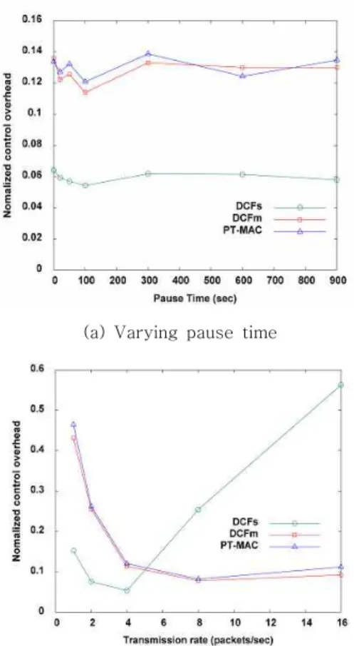
Fig. 5 represents the control overhead at various pause time and transmission rate. Fig.
5(a) shows the normalized control overhead, which is the product of total number of control packets sent divided by total number of data packets sent. The normalized control overhead considers each hop-wise transmission as one transmission. The control packet refers to the
(a) Varying pause time
(b) Varying transmission rate Fig. 5 Control overhead
packets sent during routing, other than data packets. One thing particular in Fig. 5(a) is that the control overhead of DCF
sis low. It is because there are not much control packet collision as it uses single interface. On the other hand, when DCF
mand PT-MAC are compared, it is shown that control overhead is not increased.
In other words, the proposed PT-MAC protocol
has excellent performance in reducing the
end-to-end transmission delay, without reducing
the packet delivery ratio or increasing the
control overhead. Fig. 5(b) shows that, when
PT-MAC is compared to DCF
m, its control
overhead is not higher than that of DCF
m. For
these two protocols, the reason why their
control overhead decreases when the
transmission rate is 8 or lower is because, if
there is less traffic, the routing table is not
updated frequently enough that the routing expiry happens often and route disconnection increases. For DCF
s, unlike PT-MAC and DCF
m, the control overhead decreases at the transmission rate lower than 4 but then drastically increases at the transmission rate higher than 4. It is because DCF
sis a single-channel interface, with less network accommodation than PT-MAC and DCF
m.
From the simulation results, it can be easily inferred that the proposed PT-MAC shows excellent performance improvement without increasing control overhead.
V. Conclusions
This paper aimed at improving overall performance of entire network through multihop transmission in mobile ad hoc networks. For this, the pipeline-through MAC protocol has been proposed for mobile ad hoc networks composed of nodes with two 3-channel interfaces.
By applying the pipeline-through technique instead of the conventional store-and-forward method, the proposed protocol succeeded in minimizing the transmission delay caused by intermediate nodes on multihop transmission path to store packets and thus resulted in significantly reducing the end-to-end delay. In order to validate the proposed protocol and evaluate its performance, the pipeline-through MAC protocol was implemented using ns-2 and tested under the simulation environment. The simulation results showed that the proposed PT-MAC protocol reduced the end-to-end delay by 20-44% from DCF and increased the goodput by 26-56%, in comparison to DCF, under the same channel same interface conditions, without lowering the packet delivery ratio or increasing the control overhead.
For future projects of this study, pipeline-through MAC protocol that takes asymmetric links into consideration and the one in the network that uses directional
antennas will be studied.
References
[1] H. Zhu, G. Cao, “On Improving the Performance of IEEE 802.11 with Relay-Enabled PCF,” ACM/Kluwer Mobile Networking and Applications (MONET), Vol. 9, No. 4, pp.423-434, 2004.
[2] IEEE, “Wireless LAN Medium Access Control (MAC) and Physical Layer (PHY) Spec,” IEEE 802.11 Standard, 1999.
[3] Y. Seok, J. Park, Y. Choi, “Multirate Aware Routing Protocol for Mobile Ad Hoc Networks,”
Proeedings of IEEE Conference on Vehicular Technology, pp. 22-25, 2003.
[4] IEEE WG, “IEEE Std 802.11a-1999, Part 11:
Wireless LAN Medium Access Control(MAC) and Physical Layer(PHY) specification, Amendment 1: High-speed physical Layer in the 5 GHz band,” 1999.
[5] IEEE WG, “IEEE Std 802.11b-1999, Part 11:
Wireless LAN Medium Access Control(MAC) and Physical Layer(PHY) specification, Higher-speed Physical Layer Extension in the 2.4 GHz band,” 1999.
[6] B. Awerbuch, D. Holmer, H. Rubens, “High Throughput Route Selection in Multi-Rate Ad Hoc Wireless Networks,” Proceedings of Working Conference on Wireless On-demand Network Systems (WONS), 2004.
[7] D.S.J. DeCouto, D. Aguayo, J. Bicket, R.
Morris, “A High-Throughput Path Metric for Multihop Wireless Routing,” Proceedings of ACM Mobicom, pp.134-146, 2003.
[8] A. Kamerman, L. Monteban, “WLAN-II: A High-Performance Wireless LAN for the Unlicensed Band,” Bell Labs Technical Journal, Vol. 2, No. 8, pp.118-133, 1997.
[9] G. Holland, N. Vaidya, P. Bahl, “A Rate-Adaptive MAC Protocol for Multihop Wireless Networks,” Proceedings of ACM Mobicom, pp.236-251, 2001.
[10] J. Park, H. Shin, S. Moh, “Pipeline-Through
Medium Access Control for Mobile Ad Hoc
Networks,” Proceedings of Int. Conf. on Smart Media and Applications (SMA 2012), pp.A6.1-A6.4, 2012.
[11] B. Sadeghi, V. Kanodia, A. Sabharwal, E.
Knightly, “Opportunistic Media Access for Multirate Ad Hoc Networks,” Proceedings of ACM Mobicom, pp.24-35, 2002.
[12] J. Gomez, A.T. Campbell, M. Naghshineh, C.
Bisdikian, “Conserving Transmission Power in Wireless Ad Hoc Networks,” Proceedings of IEEE Int. Conf. on Network Protocols (ICNP), 2001.
[13] H. Zhu, G. Cao, “rDCF: A Relay-Enabled Medium Access Control Protocol for Wireless Ad Hoc Networks,” IEEE Trans. on Mobile Computing, Vol. 5, No. 9, pp.1201-1214, 2006.
[14] The Network Simulator ns-2, http://www.isi.edu/nsnam/ns, 2011.
Authors
Jiwon Park
2007: B.E. degree in computer engineering from Chosun University, Korea
2010: M.E. degrees in computer engineering from Chosun University, Korea
Current: Senior researcher at Sunggwang Inc., Gwangju, Korea
Research interests: Mobile networks, wireless ad hoc and sensor networks, and system programming
Email: [email protected]
Sangman Moh
1991: M.S. degree in computer science from Yonsei University, Korea
2002: Ph.D. degree in computer engineering from Korea Advanced Institute of Science and Technology (KAIST), Korea
1991-2002: Project leader at Electronics and Telecommunications Research Institute (ETRI), Korea
Current: Professor in the Dept. of Computer Engineering at Chosun University, Korea
Research interests: Mobile computing and networking, ad hoc and sensor networks, cognitive radio networks, and parallel and distributed computing systems
Email: [email protected]