AJCPP 2008 March 6-8, 2008, Gyeongju, Korea
Fuel Cell Powered UAV with NaBH 4 as a Hydrogen Source
Taegyu Kim, Hyunchul Shim, Sejin Kwon Department of Aerospace Engineering, KAIST Gwahangno 335, Yusung-gu, Daejeon, Repulic of Korea
[email protected]
Keywords: fuel cell, sodium borohydride, unmanned aerial vehicle Abstract
PEM Fuel cell system was designed and constructed to use as a power source of unmanned aerial vehicles (UAV) in the present study. Sodium borohydride was selected as a hydrogen source and was decomposed by catalytic hydrolysis reaction. Fuel cell system consists of a fuel cell stack, a hydrogen generation system (HGS), and power management system (PMS). HGS was composed of a catalytic reactor, micropump, fuel cartridge, and separator.
Hybrid power system between lithium-polymer battery and fuel cell was developed. The fuel cell system was integrated and packaged into a blended wing-body UAV. Energy density of the total system was 1,000 W·hr/kg and high endurance more than 5 hours was accomplished in the ground tests.
Introduction
Small unit UAV is being developed to perform the search and reconnaissance for small troops 1) . However, its endurance is limited to less than 1 hour and mission range to 10 km. The limitation is caused by its existing power sources that include internal combustion engines (ICE) or lithium-polymer batteries (LIB). ICE is not favorable to the reconnaissance due to its vibration and noise. LIB has the limited duration less than one hour due to its low energy density. Fuel cell is simple, noiseless, and efficient device that converts directly the chemical energy of fuel into the electricity 2) .
PEM fuel cell was used as a power source of a UAV in the present study. Pure hydrogen is required as a fuel for fuel cell. However, gaseous hydrogen is not suitable in UAV applications due to its low density. Though it is possible to use hydrogen in either compressed gas 3) or liquid form, it gives significant hazards due to its explosive nature. Sodium borohydride, which is stored in a liquid state, was selected as a hydrogen source in the present study.
Blended wing-body (BWB) UAV was used to validate high endurance of a fuel cell powered airplane.
Sodium borohydride
Sodium borohydride is stored in liquid phase at the atmospheric pressure and temperature. It is stable and nonflammable alkaline solution. In addition, it has relatively high hydrogen content and is renewable and environmentally friendly fuel.
Sodium borohydride is decomposed to generate hydrogen though catalytic hydrolysis reaction below 4)
NaBH 4 + 2H 2 O → NaBO 2 + 4H 2
Ruthenium, platinum, and cobalt metal catalyst have been used for the fast production of hydrogen.
Hydrogen is only gas product in the reaction and therefore pure hydrogen can be obtained after separating the borate. The borate can be recycled into sodium borohydride that is an original fuel. No heat input is required because the hydrolysis reaction is exothermic.
Hydrogen generation
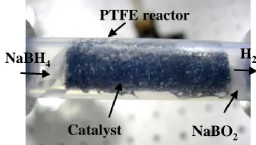
Catalytic microreactor for hydrogen generation from sodium borohydride is shown in Fig. 1.
Polytetra-fluoroethylene (PTFE), which is transparent, was used as a material of the reactor to monitor the reaction process. Cobalt-based catalyst 5) was prepared by wet impregnation-reduction method. Porous ceramic material (ISOLITE ® ) was selected as a catalyst support 6) . SEM analysis of the surface of a prepared catalyst shows a high porous and large surface area in Fig. 2.
Hydrogen production rate as a function of reaction time is presented in Fig. 3. Feed rate of reactants was 20 ml/h and the concentration of sodium borohydride was 25%. Hydrogen production rate was low when the reaction was initiated because the temperature was low and the reaction rate was slow. The temperature increased with the production rate as the reaction time elapsed because the hydrolysis is an exothermic reaction. After 80 seconds, the hydrogen production rate reached nearly theoretical maximum. This means the conversion of sodium borohydride was 100% on the prepared catalyst. It can be seen that a robust catalyst layer was coated on the support.
NaBH 4
Catalyst NaBO 2 H 2 PTFE reactor
Fig. 1 Catalytic reactor for hydrogen generation from sodium borohydride
579
AJCPP 2008 March 6-8, 2008, Gyeongju, Korea
Fig. 2 SEM image of the surface of a catalyst-coated ceramic support
Fig. 3 Hydrogen production rate and temperature change as a function of reaction time at the feed rate
of 20 ml/h
Fig. 4 Performance curve of a fuel cell stack at the hydrogen flow of 300 sccm
Fuel cell system
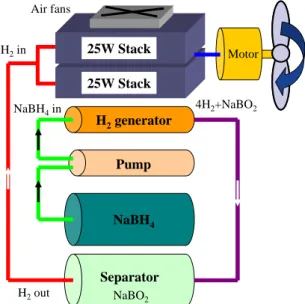
Total fuel cell system consists of hydrogen generation system (HGS), fuel cell stack, and power management system (PMS). Commercially available PEMFC was used, which was fabricated by stacking 24 cells that have 3.8 cm 2 active area, resulting in the 25 W maximum power level. Performance curve of the fuel cell stack is shown in Fig 4. HGS was composed of catalytic reactor, micropump, fuel cartridge, and separator. Layout of fuel cell system
with HGS is presented in Fig. 5. Operating principle is as follows. Micropump supplies sodium boro- hydride contained in the fuel cartridge to catalytic reactor. Sodium borohydride is decomposed to produce sodium borate and hydrogen. Sodium borate is removed in the separator and pure hydrogen is only provided to the fuel cell. The fuel cell generates the electricity that operates the electric motor to produce the propulsion.
Fuel cell and hydrolysis reaction are exothermic process. The heat load was removed to maintain the optimal temperature in the fuel cell system. Water- cooling method has been used. However, it is complex and bulky. Atmosphere air flow through the intake when the air vehicle was flying was circulated to cool the fuel cell system. Total heat balance between fuel cell system and UAV are given below and a cruise speed range was determined:
4
( ) ( ) 0
C NaBH MAV s s
I
i H V H h v A T T
η nF
∞⎡ ⎛ −Δ ⎞ − ⎤ + Δ + − <
⎢ ⎜ ⎟ ⎥
⎝ ⎠
⎣ ⎦
(1)
Integrated fuel cell power train is shown in Fig. 6.
Assembled hydrogen generation system is shown in Fig. 7. Storable weight of fuel is 500 g. The stored energy is 637 W·hr and total energy density is 931 W·hr/kg that is 5 times higher than existing batteries.
The fuel cell system loaded into a UAV is shown in Fig. 8. Weight distribution of total fuel cell system is presented in Fig. 9. Fuel cell dominated the system weight. Hydrogen generation system was 23%, which is a satisfactory portion compared to a compressed hydrogen.
Schematic of power management system (PMS) is shown in Fig. 10. Hybrid power control between fuel cell and lithium-polymer battery was performed.
Take-off is initially powered by a battery. Power is switched to fuel cell during the flight, and the battery is recharged.
H 2 generator
Pump
NaBH 4
4H
2+NaBO
2H
2in
NaBO
2Separator H
2out
NaBH
4in
Motor 25W Stack
25W Stack Air fans
Fig. 5 Layout of a fuel cell system with hydrogen generation system
Current (A)
S tac k p o te n ti al (V ) St a c k p o w e r (W )
0 0.5 1 1.5 2
0 5 10 15 20
0 5 10 15 20
Reaction time (min)
Te m p e ra tur e (
oC) H
2pr o duc ti o n ra te (m l/ m in)
0 1 2 3 4 5 6 7 8 20
25 30 35
0 50 100 150 200 250 300 350
Theoretical maximum
580
AJCPP 2008 March 6-8, 2008, Gyeongju, Korea
Stack Receiver
Micro-pump H
2generator Controller
Fuel cartridge Separator Speed
controller
Motor
Fig. 6 Integrated fuel cell power train
Pump
Fuel cartridge Reactor
Fuel port Pump
Fuel cartridge Reactor
Fuel port
Fig. 7 Assembled hydrogen generation system
Fig. 8 Packaging of fuel cell system in a UAV
Fig. 9 Weight distribution of total fuel cell system
Fuel cell
Pump FAN
10-20V Unregulated
DC input
12V Regulated DC output
11.1V 1200mA
3 cells 11.1V 4,000mAh
PMS DC/DC
Converter
Charger/
Balancer
Li-Poly Battery
IMU ESC Motor
Voltage, current, temperature
Motion Power
Power flow Feedback signal Control signal
ESC: Electric Speed Controller IMU: Inertial Measurement Unit
Fig. 10 Hybrid power management system of fuel cell and lithium-polymer battery
Specification Value Wing span
Wing area Aspect ratio Empty weight
Maximum take-off weight Wing loading
Cruise speed
1.52 m 0.52 m 2 4.43 1.2 kg 2.5 kg
22.4 – 41.1 N/m 2 7.2 – 9.8 m/s Fig. 11 Blended wing-body air vehicle
Flight test
Blended wing-body (BWB) UAV 7) was used to validate the fuel cell system as a power source. BWB is combination of flying wing and lifting body and entire body contributes to lift generation. Lifting body part provides sufficient volume to mount fuel cell components. An image of the UAV is presented in Fig.
11. The fuel cell UAV has performed nine test flights to date. Though six test flights were failed, the system design has been changed and optimized. Three successful flights has made with fuel cell system and show that fuel cell UAV is capable of high endurance and high performance.
Conclusion
Energy density of the state-of-art batteries is inadequate for extended operation of a UAV. PEM fuel cell with sodium borohydride as a hydrogen source is proposed in the present study. Pure hydrogen
PMS 10%
Receiver 4%
Connector 2%
HGS 23%
Fan 5%
Fuel cell 44%
LIB 12%