Vol. 24, No. 5 (2014) 207-212
http://dx.doi.org/10.6111/JKCGCT.2014.24.5.207
e-ISSN 2234-5078
Synthesis of carbon nanosheets using RF thermal plasma
Seung-Yong Lee *
,**, Sang-Min Ko*, Sang-Man Koo**, Kwang-Taek Hwang*, Kyu-Sung Han* and Jin-Ho Kim*
,†*Icheon Branch, Korea Institute of Ceramic Engineering and Technology, Icheon 467-843, Korea
**Department of Chemical Engineering, Hanyang University, Seoul 133-791, Korea (Received September 15, 2014)
(Revised October 17, 2014) (Accepted October 22, 2014)
Abstract An ultrathin sheet-like carbon nanostructure provides an important model of a two-dimensional graphite structure with strong anisotropy in physical properties. As an easy and cheap route for mass production, RF thermal plasma synthesis of freestanding carbon nanosheet from CH
4(Methane) and C
3H
8(Propane) is presented. Using vapor synthesis process with RF inductively thermal plasma, carbon nanosheets were obtained without catalysts and substrates. The synthesized carbon nanosheets were characterized using transmission electron microscopy (TEM), Raman spectroscopy, X- ray diffraction (XRD) and Brunauer-Emmett-Teller (BET) analysis. The carbon nanosheets synthesized using methane and propane generally showed 5~6 and 15~16 layers with a wrinkled morphology and size of approximately 100 nm.
Key words Carbon nanosheet, RF thermal plasma, Vapor synthesis, Methane, Propane
유도 열플라즈마를 이용한 카본나노시트 합성
이승용*
,**, 고상민*, 구상만**, 황광택*, 한규성*, 김진호*
,†* 한국세라믹기술원 이천분원, 이천, 467-843
**한양대학교 화학공학과, 서울, 113-791 (2014년 9월 15일 접수)
(2014년 10월 17일 심사완료) (2014 년 10월 22일 게재확정)
요 약 2차원 흑연구조를 갖는 카본나노시트는 큰 비표면적과 우수한 전기적, 화학적 및 기계적 물성으로 인하여 미래 소재로 각광받고 있다. 경제적이고 쉬운 카본나노시트의 양산공정개발을 위해 본 연구에서는 메테인(CH
4)과 프로페인 (C
3H
8) 가스를 이용한 유도 열플라즈마 공정을 통해 기상 합성하여 카본나노시트 분말을 합성하였다. 유도 열플라즈마를 이용한 카본나노시트 합성은 촉매나 증착공정 없이 진행되었으며, 합성된 카본나노시트의 물성을 TEM, Raman, XRD, BET로 분석하였다. 메테인과 프로페인으로부터 합성된 카본 나노시트는 각각 5~6개의 그래핀 층과 15~16개의 그래핀 층 으로 이루어진 분말로 합성되었으며 분말의 크기는 약 100 nm임을 확인할 수 있었다.
1. 서 론
카본나노시트(Carbon nanosheet)는 이차원 sp
2탄소 결 합 골격을 가지며, 큰 비표면적과 우수한 전기적, 화학적 및 기계적 물성을 가진 소재로 리튬 전지의 음극 소재, 연료전지 촉매, 기능성 복합재료의 충진제 등 많은 분야 에 응용 및 연구가 활발히 진행되고 있다[1-5]. 카본나노
시트 제조 방법은 일반적으로 화학적 박리법(Chemical exfoliation) 과 화학증기 증착법(Chemical vapor deposition) 이 알려져 있다[6]. 화학적 박리법은 흑연 결정을 강한 산으로 산화시키고 초음파 처리 후 환원제를 이용하여 카본나노시트를 제조하는 방법으로 대량생산이 가능하고, 환원 공정 중 다양한 기능기 도입이 가능하여 쉽게 카본 나노시트의 기능화가 용이하지만 고품질의 카본 분말 생 산이 어렵다는 단점이 있다. 화학증기 증착법은 고온에 서 탄소와 카바이드 합금을 쉽게 형성하거나 탄소를 손 쉽게 흡착하는 전이금속을 촉매 층으로 이용하여 합성하 는 방법으로 주로 촉매와 기판을 필요로 하며 공정의 고
†
Corresponding author
†
Tel: +82-31-645-1432
†
Fax: +82-31-645-1485
†
E-mail: [email protected]
비용으로 인한 양산화가 어렵다는 문제점이 있다[7].
본 연구에서는 분말 제조에 있어 보다 실용적이고 간 편한 특징을 가지고 있는 유도 열플라즈마 합성법(RF thermal plasma process) 을 이용하여 카본나노시트를 제 조하였다. 유도 열플라즈마 합성법은 다양한 기상, 액상, 고상의 출발 물질을 사용하여 나노분말로 제조할 수 있 으며, 10,000 K 이상의 고온 플라즈마에 의한 빠른 반응 속도로 출발 원료의 손실을 최소화하며 분말의 대량생산 이 가능하고, 플라즈마 분위기와 냉각 속도 제어를 통해 원하는 입도 및 결정구조를 가지는 분말을 합성하는 것 이 가능한 특징을 가진다[8-10]. 카본나노시트는 -C를 가지는 메테인(CH
4) 과 프로페인(C
3H
8) 가스를 이용하여 합성되었고 출발 원료에 따른 카본나노시트의 미세구조 및 결정성을 비교 분석하였다.
2. 실험방법
2.1. 유도 열플라즈마 장치구성
카본나노시트 합성에 사용된 유도 열플라즈마 장비 (TDU-30, Tekna) 의 개략도를 Fig. 1에 나타내었다. 유도 열플라즈마 합성은 고온(10,000 K), 고활성 및 초급냉의 특징을 가지며 다양한 출발 원료를 사용 가능하고 연속 적으로 대량생산이 가능한 공정이다. 유도 열플라즈마 합성장치는 플라즈마 토치(Torch), 반응관(Reactor), 사이 클론(Cyclone), 필터부(Filter)로 구성되며, 플라즈마를 거쳐서 합성된 분말은 입도에 따라서 반응관, 사이클론, 필터부의 하단에 분리되어 포집된다. Central gas는 토치 에서 분사되어 플라즈마를 형성하며, Dispersion gas는
플라즈마 내에서 출발 원료의 기상화를 용이하게 한다.
Sheath gas 는 고온의 플라즈마 영역에서 토치 내벽을 보 호하고 안정된 플라즈마 흐름을 갖게 하며, Quenching gas 는 생성된 플라즈마 끝 부분에 분사되어 생성된 분말 을 급냉시켜 입자크기를 제어하는 역할을 한다. 본 연구 에서는 입도가 작고 균일한 필터부 하단에서 포집된 카 본나노시트 분말을 이용하여 분석하였다.
2.2. 카본나노시트 분말의 합성 및 분석 방법
출발 원료로 메테인(CH
4, 99.999 %) 과 프로페인(C
3H
8, 99.999 %) 가스를 사용하여 카본나노시트를 합성하였으며, Central gas, Dispersion gas, Sheath gas 는 Ar(99.999 %) 을 사용하였으며 Quenching gas는 N
2(99.999 %) 를 사 용하였다. 플라즈마 출력, 반응관 압력, 출발 원료 주입 속도는 일정하게 유지하였으며 자세한 유도 열플라즈마 합성 조건을 Table 1에 나타내었다.
합성된 카본나노시트는 X-ray diffractometer(XRD, D/
MAX2500VL/PC, Rigaku) 와 Laser Raman Spectrophotometer
Fig. 1. Schematic diagram of RF thermal plasma system.
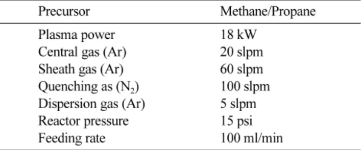
Table 1
Experimental conditions of RF thermal plasma for carbon nanosheet synthesis
Precursor Methane/Propane
Plasma power 18 kW
Central gas (Ar) 20 slpm
Sheath gas (Ar) 60 slpm
Quenching as (N
2) 100 slpm
Dispersion gas (Ar) 5 slpm
Reactor pressure 15 psi
Feeding rate 100 ml/min
(Jasco NRS-3100) 을 이용하여 결정구조를 분석하였고, TEM(G2 F30 S-Twin, Tecnai) 으로 형상 및 미세구조 분석을 수행하였다. 합성된 카본나노시트의 비표면적은 150
oC 에서 4시간 동안 건조한 후 77 K에서 질소를 흡착 시켜 BET(Belsorp II mini, BEL)로 측정하였다.
3. 결과 및 고찰
3.1. 카본나노시트 분말의 결정구조 분석
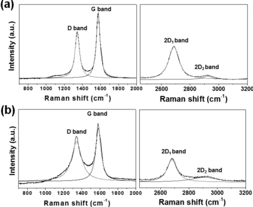
메테인과 프로페인을 출발 원료로 사용하여 합성한 카 본나노시트 분말의 라만 스펙트럼 분석 결과를 Fig. 2에 나타내었다. 일반적으로 탄소 소재는 D band(~1350 cm
−1), G band(~1580 cm
−1), 2D band(~2700 cm
−1) 에서 주요 피크를 나타내며, 각 피크의 intensity ratio를 분석하여 결정성과 층수를 확인할 수 있다[11-13]. D band는 비 정질상의 탄소나 결함 등에 의해 나타나는 피크로 화학 반응이나 물리적 처리에 의해 원자 수준의 결함이 생기 게 되면 강한 신호를 보이며, 흑연계 물질에서 공통으로 나타나는 G band는 sp
2결합을 하는 탄소 결합과 관련 된 피크이다. D band와 G band의 intensity ratio(I
D/I
G) 로 합성된 카본나노시트의 품질을 평가할 수 있으며, 2D band 와 G band의 intensity ratio(I
2D/I
G) 를 통해 카본 나노시트의 층수를 분석할 수 있다.
메테인으로부터 합성된 카본나노시트 분말의 라만 스 펙트럼 분석 결과 G band는 1581 cm
−1, D band 는 1341 cm
−1, 2D
1band 는 2687 cm
−1, 2D
2band 는 2924 cm
−1에 서 관찰되었으며, 프로페인으로부터 합성된 카본나노시 트 분말의 경우 각각 1573 cm
−1, 1343 cm
−1, 2680 cm
−1, 2935 cm
−1에서 관찰되었다. 메테인과 프로페인을 이용하 여 합성된 카본나노시트 분말의 I
D/I
G는 각각 0.69와 0.71 로 이러한 결과는 메테인으로부터 합성된 카본나노 시트가 프로페인으로부터 합성된 카본나노시트보다 작은 면적으로 인해 상대적으로 많이 존재하는 그래핀 층 edge 부분의 결함 때문인 것으로 판단된다[14]. I
2D/I
G의 경우 단일 층의 그래핀일 때 1.5, 두 개의 층으로 이루 어진 그래핀은 1.5~0.95, 그 이상의 층수를 가지는 경우 0.95 이하의 값이 나타난다[15]. 단일 층의 그래핀과 카 본나노시트를 비교할 때 그래핀은 G band에 비하여 2D band 의 intensity가 높게 나타나나[16], 메테인과 프로페 인으로 합성된 카본나노시트 분말은 G band의 intensity 가 2D band의 intensity보다 크게 나타나며 I
2D/I
G가 각 각 0.59와 0.74로 그래핀 층수가 3층 이상임을 확인하 였다[17]. 또한 2D band는 흑연에서 2D
1과 2D
2의 2개 의 피크로 나타나나 합성된 카본나노시트 분말은 2D
1band 에 비해 2D
2band 의 intensity가 매우 약하게 나타 나 수 개의 그래핀 층으로 이루어져 있음을 확인할 수 있었다.
Fig. 3(a) 는 출발 원료를 메테인을 사용하여 합성된 카
Fig. 2. Raman spectra of carbon nanosheets synthesized using (a) methane, (b) propane.
본나노시트 분말의 X-ray diffraction 분석 결과이다. 26
o와 44
o에서 각각 graphite 상의 (002)면와 (100) 면에 의 해 나타나는 회절 피크가 관찰되었으며 Bragg’s equation 과 Scherrer’s equation을 이용하여 면간거리와 grain크 기를 계산하여 합성된 카본나노시트의 그래핀의 층수를 확인하였다[13, 18].
n λ = 2dsinθ (1)
λ는 X-ray의 파장(0.154 nm), θ는 회절 각도, d는 면 간 거리를 나타내며 합성된 카본나노시트의 (002)면의 면간 거리는 0.36 nm로 계산되었다.
(2)
L 은 grain 크기이고, K는 scherrer 상수로 c축 방향의 경우 0.98이며, λ는 X-ray의 파장, β와 θ는 각각 피크의 FWHM(full width half maximum) 과 회절 각도를 나타 낸다[12]. (002)피크의 경우 FWHM은 9.29이며 c축 방 향의 grain 크기는 0.87 nm로 계산되었다. 면간 거리와 grain 크기를 통하여 메테인으로부터 합성된 카본나노시 트 분말은 약 2~3개의 그래핀 층으로 이루어진 것을 확 인하였다[19].
Fig. 3(b) 는 출발 원료를 프로페인으로 하여 합성한 카 본나노시트 분말의 X-ray diffraction 분석 결과를 나타 낸다. 메테인으로 합성된 분말과 동일하게 graphite의 (002) 면과 (100)면에 의한 회절 피크가 관찰되며, 메테인 으로 합성된 카본나노시트에 비해 (002)피크의 intensity 가 다소 증가하였고 FWHM을 확인한 결과 1.44로 감소 한 것을 확인하였다. 이러한 결과는 메테인에 비해 C원 소가 많이 포함된 프로페인을 출발 원료로 사용한 결과 입자 성장이 더 많이 발생하여 결정성이 좋아진 것으로 판단된다. 프로페인으로부터 합성된 카본나노시트 분말 은 (002)면의 면간 거리와 c축 방향의 grain 크기가 각 각 0.36 nm과 5.58 nm로 계산되었고, 이로부터 약 15~
16 개의 그래핀 층을 포함하는 것을 확인하였으며, Fig.
2 의 라만 스펙트럼 분석과도 일관성 있는 결과를 보여주 고 있다[20].
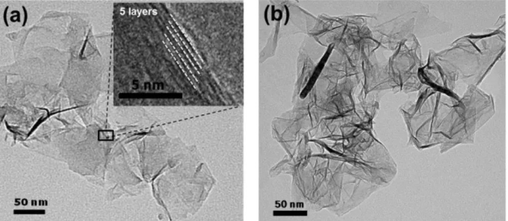
3.2. 카본나노시트 분말의 형상 및 미세구조 분석 합성된 카본나노시트 분말의 미세구조 분석을 위하여 TEM 이미지를 Fig. 4에 나타내었다. Fig. 4(a)는 메테인 으로 합성된 카본나노시트의 TEM 이미지로 약 50 nm 크기의 시트 형상으로 관찰되며 edge 부분을 HR-TEM L = K λ
β cos θ ---
Fig. 4. TEM images of carbon nanosheets synthesized using (a) methane, (b) propane.
Fig. 3. X-ray diffraction patterns of carbon nanosheets synthesized using (a) methane, (b) propane.
을 이용하여 관찰한 결과 약 5~6개의 그래핀 층을 관찰 할 수 있었다. Fig. 4(b)는 프로페인을 사용하여 합성한 카본나노시트이며 대부분 100 nm 이상의 크기를 보인다.
또한 프로페인으로 합성된 카본나노시트의 경우 넓은 면 적으로 인한 표면에너지의 최소화에 의해 메테인으로 합 성된 카본나노시트보다 edge 부분이 말려있거나 주름진 형상이 많이 관찰된 것으로 판단된다[12, 21, 22].
Table 2 에 메테인과 프로페인으로 합성된 카본나노시 트 분말의 비표면적 측정 결과를 나타내었다. 카본나노 시트의 비표면적은 메테인과 프로페인을 사용한 경우 각 각 500 m
2/g 와 192 m
2/g 로 측정되었으며, 기존에 보고된 1~2 층 그래핀의 비표면적이 2600 m
2/g 인 결과와 비교해 볼 때 메테인으로 합성된 카본나노시트는 약 5~6개의 그래핀 층으로 포함하고, 프로페인으로 합성된 카본나노 시트는 약 15~16개의 그래핀 층으로 이루어져 있는 것 을 예상할 수 있으며 Fig. 3의 X-ray diffraction 결과와 Fig. 4 의 TEM 이미지와도 일관된 결과임을 확인할 수 있었다[11, 23].
4. 결 론
유도 열플라즈마를 이용하여 서로 다른 기상의 출발 원료에 따라 합성된 카본나노시트의 결정구조 및 미세구 조를 비교 분석하였다. 메테인과 프로페인을 이용하여 합성된 카본나노시트 분말은 sp
2결합의 흑연계 물질의 결정구조를 나타내며 각각 약 50 nm와 100 nm 이상의 입도와 500 m
2/g 과 192 m
2/g 의 비표면적을 가지는 것을 확인할 수 있었다. 프로페인으로 합성된 경우 카본나노 시트의 edge 부분은 다소 주름진 형상을 보이며, X-ray diffraction 과 TEM 분석 결과 메테인으로부터 합성된 카 본나노시트는 약 5~6개의 그래핀 층을 가지며, 프로페인 으로부터 합성된 카본나노시트는 15~16개의 그래핀 층 을 가지는 것을 확인하였다.
감사의 글
본 연구는 산업통상자원부 WPM(World Premier Materials) 사업의 연구비 지원으로 수행되었습니다.
References