pISSN 1229-3008 eISSN 2287-6251
Progress in Superconductivity and Cryogenics
Vol.17, No.3, (2015), pp.57~61 http://dx.doi.org/10.9714/psac.2015.17.3.057
```
1. INTRODUCTION
Fault current limiter is concept of an electric power device to protect electric power system from unexpected occurrence of fault current. With progresses of superconducting technologies and developments of large scale power grid, superconducting fault current limiter (SFCL) will take place as a new alternative in fault current limiting technology in electric power grid [1].
The SFCL is a device that limits quickly the fault current by using the impedance characteristics of the superconductor in normal operation condition. A large amount of heat is generated by outbreak of the fault current in the SFCL. A cryogenic cooling of the SFCL is an essential prerequisite to safely protect superconducting elements from the heat generation and to promptly recover them to the normal operation condition.
When the fault current occurs, the heat is generated in a short time but the amount is very large. Typical cryocoolers cannot remove the heat generated within the recovery time required by the power grid. Consequently, liquid cooling using subcooled LN2 are widely used for the cryogenic cooling of the SFCL. In general, SFCL modules are submerged in sub-cooled liquid nitrogen for their stable thermal characteristics.
Cooling superconducting elements in subcooled LN2 at below the normal boiling point (77 K) and elevated pressure is a good choice in many respects.
The critical current of the SFCL is increased at low temperature, so the size of the superconducting elements
and the cryogenic system can be reduced.
The heat dissipation during the fault current-limiting process generates bubbles by vaporization of the liquid nitrogen, resulting in the deterioration of the electric insulation. The use of the subcooled LN2 at elevated pressure can suppress the generation of bubble and evade the occurrence of the cavitation in the cooling system [2-5].
However, the use of the subcooled LN2 at the elevated pressure leads to drawbacks in the design of the pressure vessel and the cooling capacity of the cryocooler.
Several cryogenic cooling systems have been successfully developed for the distribution class SFCL in the subcooled LN2 [6, 7]. On the other hand, transmission class SFCL has not been developed.
Recently, due to higher demand in a transmission level, 154 kV / 2 kA SFCL has been developed in Korea. The SFCL is resistive type and uses quench phenomena in HTS tapes to limit the fault current. The normal operation condition of the 154 kV SFCL is 71 K and 500 kPa. This paper reports the performance of the cooling system for the 154 kV class SFCL during the cool-down period.
2. COOLING SYSTEM CONFIGURATION The cooling system for the 154 kV single phase SFCL consists of a Main Cryostat (MC), a Subcooling Cryostat (SC), a Pressure builder (PB) and a cryocooler as shown in Fig. 1. The MC is responsible for the cooling of SFCL modules below the critical temperature by removing the dissipated heat by the circulation of the subcooled LN2.
Cool-down test of cryogenic cooling system for superconducting fault current limiter
Yong-Ju Hong*,a, Sehwan Ina, Han-Kil Yeoma, Heesun Kimb, and Hye-Rim Kim b
a Korea Institute of Machinery & Materials, Daejeon, Korea
b KEPCO Research Institute, Daejeon, Korea
(Received 10 August 2015; revised or reviewed 16 September 2015; accepted 17 September 2015)
Abstract
A Superconducting Fault Current Limiter is an electric power device which limits the fault current immediately in a power grid.
The SFCL must be cooled to below the critical temperature of high temperature superconductor modules. In general, they are submerged in sub-cooled liquid nitrogen for their stable thermal characteristics. To cool and maintain the target temperature and pressure of the sub-cooled liquid nitrogen, the cryogenic cooling system should be designed well with a cryocooler and coolant circulation devices. The pressure of the cryostat for the SFCL should be pressurized to suppress the generation of nitrogen bubbles in quench mode of the SFCL. In this study, we tested the performance of the cooling system for the prototype 154 kV SFCL, which consist of a Stirling cryocooler, a subcooling cryostat, a pressure builder and a main cryostat for the SFCL module, to verify the design of the cooling system and the electric performance of the SFCL. The normal operation condition of the main cryostat is 71 K and 500 kPa. This paper presents tests results of the overall cooling system.
Keywords: Superconducting Fault Current Limiter, Cryogenic Cooling, Cool-down
* Corresponding author: [email protected]
Cool-down test of cryogenic cooling system for superconducting fault current limiter
Fig. 1. Schematic diagram of cooling system for the 154 kV SFCL.
The volume of the MC is 30 m3, and it was filled with approximately 23 ton of the subcooled LN2. The LN2 is supplied from the bottom of the MC, and returned at the height of 85 % of the MC, so that the LN2 should be filled with the LN2 up to above 85 % height of the MC.
The SC, which is consisting of a heat exchanger, a hydro cyclone and a LN2 circulation pump, is responsible for the subcooling of the LN2. The hydrocyclone is used to filter out particles with diameter of 50 ㎛ or more to prevent partial discharge under high electric voltage in the MC.
The heat exchanger with the capacity of 4 kW and the LN2
circulation pump (Barber-Nichols Inc., BNCP-64C), which are used to cool the LN2 down to 71 K, were installed.
The PB is responsible for the maintaining the pressure of the MC at 500 kPa. It is automatically controlled by the set pressure using a 2 kW heater and a solenoid valve.
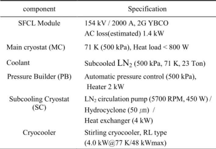
A Stirling cryocooler (Stirling Cryogenics, SPC-04) is responsible for the re-liquefaction (RL) of the evaporated nitrogen due to the heat duty of the heat exchanger. Table 1 shows the detailed specifications of the cooling system.
TABLEI
SPECIFICATIONOFTHECOOLINGSYSTEM.
component Specification
SFCL Module 154 kV / 2000 A, 2G YBCO AC loss(estimated) 1.4 kW Main cryostat (MC) 71 K (500 kPa), Heat load < 800 W Coolant Subcooled LN2 (500 kPa, 71 K, 23 Ton) Pressure Builder (PB) Automatic pressure control (500 kPa),
Heater 2 kW Subcooling Cryostat
(SC) LN2 circulation pump (5700 RPM, 450 W) / Hydrocyclone (50 ㎛) /
Heat exchanger (4 kW) Cryocooler Stirling cryocooler, RL type
(4.0 kW@77 K/48 kWmax)
Fig. 2. Temperature changes on the surface of the MC during the precooling and LN2 filing process.
Fig. 3. Level of the LN2 in the MC during the precooling and LN2 filling process.
3. PERFORMANCE OF THE COOLING SYSTEM To demonstrate the performance of components of the MC, the PB, the SC and the cryocooler, component tests were performed [8]. Then, performance tests of the cooling system for the 154 kV SFCL were carried out. Cooling processes are composed of a purging process, a cleaning and precooling process, a LN2 filling process, a subcooling process and a pressurizing process.
First, all of cryostats were purged with nitrogen gas to remove impurities. Then, small amount of the LN2 was filled to the cryostat for the precooling.
Fig. 2 shows temperature changes of the surface of the MC. To monitor the change of temperatures, five E-type thermocouples are attached to the surface of the MC.
Attached locations (T1, T2, T3, T4, T5) are the top, the height of 90 %, 80 %, 12 % of the MC and the bottom of MC, respectively. Fig. 3 shows the level of the LN2 in the MC. In the figure, a reference time (τ= 14.6 hrs) denotes a time to replace the whole subcooled LN2 in the MC by the operation of the circulation pump.
In the experiment, a small portion of the MC was initially filled with the LN2, and the MC was to be cooled by the evaporation of the LN2 during a certain amount of
Non-dimensional time (t/)
0 1 2 3 4 5 6 7 8
Temperature (K)
60 80 100 120 140 160 180 200 220 240 260 280 300
T1T2 T3T4 T5
Non-dimensional time (t/)
0 1 2 3 4 5 6 7 8
Level (%)
0 2 4 6 8 10 12 1480 82 84 86 88 90 92
58
Yong-Ju Hong, Sehwan In, Han-Kil Yeom, Heesun Kim, and Hye-Rim Kim
time. This process is to suppress the generation of excessive thermal stress in the wall of the MC and electric bushings.
After the time of 6 τ, the residual LN2 in the MC was discharged for the cleaning of the cryostat, and the MC was filled with the LN2 up to the height of 90 % of the MC. For thermal stabilization, the evaporated nitrogen was vented during about 1.0 τ, during that period the level of the LN2
in the MC was decreased to the height of 81 % of the MC.
So, the MC was refilled up to the height of 90 % of the MC.
At the same time, the PB and the SC were filled with the LN2. Heat loads of the MC and the PB were measured as about 722 W by using boil-off calorimetry. The heat load of the LN2 pipe estimated at about 15 W, this value was based on the typical value of the heat leak of vacuum insulated pipes.
And then the vent valve of the MC was closed at the time of 8 τ, and the subcooling process was carried out by turning on the cryocooler and the LN2 circulation pump.
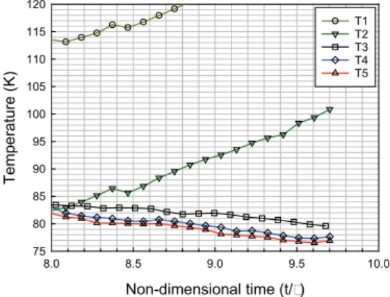
Fig. 4 shows temperature changes of the surface of the MC during the subcooling process. During the cool-down, since the LN2 was supplied to the bottom of the MC, the cooling was conducted sequentially in the order from bottom to top of the MC. As the temperature of the LN2
was decreased, the level of the LN2 in the MC was decreased as shown in Fig. 5. These phenomena come
from the densification of the LN2.
The subcooling process is a cooling process of the LN2
from temperature of the saturated liquid to the temperature of 71 K. Fig. 6 shows temperatures of the cryocooler, the saturated LN2 in the PB, the supplying LN2 to the MC and the returning LN2 from the MC, respectively. Silicon Diode temperature sensors were installed on the inlet and outlet pipe, and in the LN2 of the SC.
From the estimated thermal masses of the inner vessel of the MC, superconducting module and LN2, cool-down time is estimated at about 2.26 τ by using (1).
𝑡𝐶𝐷=∫ ��𝑀𝐶𝑝�𝐿𝑁2+�𝑀𝐶𝑝�𝑆𝐹𝐶𝐿+�𝑀𝐶𝑝�𝑉𝐸𝑆𝑆𝐸𝐿�𝑑𝑇
7177
𝑄𝑟𝑒𝑓−𝑄𝑙𝑜𝑠𝑠 (1) Where M is mass, Cp is specific heat capacity, Qref is the cooling capacity of the cryocooler, Qloss is the loss of the cooling system.
In the experiment, the cool-down time was approximately 3 τ. This difference is believed to be caused from the turn-down operation of the cryocooler during cool-down time.
As shown in Fig. 6, the temperature difference at steady state between the cryocooler and the LN2 in the SC was about 1 K, and the temperature of the LN2 in the SC was over 70 K. But the calculated temperature from the vapor
Fig. 4. Temperature changes on the surface of the MC during the subcooling pressurizing process.
Fig. 5. Level of the LN2 in the PB and the MC during the subcooling and pressurizing process.
Non-dimensional time (t/)
8.0 8.5 9.0 9.5 10.0
Temperature (K)
75 80 85 90 95 100 105 110 115 120
T1T2 T3T4 T5
Non-dimensional time (t/)
8 9 10 11 12 13 14 15 16 17 18 19 20
Level (%)
80 81 82 83 84 85 86 87 88 89 90
PB MC
Fig. 6. Temperature variation during subcooling and pressurizing process.
Fig. 7. Heat duty varation during the subcooling and pressurizing process.
Non-dimensional time (t/)
8 9 10 11 12 13 14 15 16
Temperature (K)
68 69 70 71 72 73 74 75 76 77 78 79 80
Cooler LN2 SC LN2 return LN2 supply
Non-dimensional time (t/)
8 9 10 11 12 13 14 15 16 17 18 19 20
Heat duty(kW)
0.4 0.8 1.2 1.6 2.0 2.4 2.8 3.2 3.6 4.0
59
Cool-down test of cryogenic cooling system for superconducting fault current limiter
pressure was about 69.4 K. These results indicate that the temperature gradient in the LN2 of the SC due to the heat dissipation from the immerged heat exchanger.
The temperature difference between the supplying and returning LN2 of the MC was reduced to 1 K in the steady state. Therefore temperature variations of the LN2 in the MC were determined to be maintained at less than 1 K without the operation of the SFCL. In normal operation of the 154 kV SFCL, since the heat dissipation by the superconducting element does not exceed the cooling capacity of the cryocooler, it is expected that significant changes will not occur.
Fig. 7 shows the heat duty based on the temperature difference between the supplying and returning LN2. The heat load of the MC was reduced to 880 W in steady state.
The heat load comes from the MC, the PB, the LN2 pipe and the GN2 pipe. This value was higher than the expected value of the heat loads. It is considered to have been mainly caused from the large heat load of the GN2 pipe.
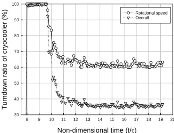
Fig. 8 shows the performance of the Stirling cryocooler during the subcooling and pressurizing process. The Stirling cryocooler could modulate the cooling capacity with the control of the rotational speed or the pressure of the helium gas. In early stage of operation, the Stirling cryocooler was operated at maximum load condition.
According to the reduction of the heat load as shown in Fig.
7, the Stirling cryocooler turned the cooling capacity down to the 36 % of the full capacity.
Fig. 9 shows the change of the pressure in the PB and the MC. The initial pressurization was carried out by the charging of the nitrogen gas to the gas space of the PB and the MC. Pressure control was achieved by the operation of the submerged 2 kW electric heater in the PB to evaporate the LN2 and by the operation of the relief valve. As shown in Fig. 9, at the time of 10 τ, the pressure of the MC and the PB approached to a set value of pressure. And then, during the period of τ, the pressure was maintained to a set value without the operation of the relief valve. As shown in Fig.
5, continuous evaporations of the LN2 in the PB resulted in the decrease of the level of the LN2. So, at the time of 11τ, it was carried out to supply the LN2 from the MC to the PB until the level of LN2 reached the level of 88%. At this time, there were no significant changes in the level of the LN2 in the MC. After the replenishment of the LN2 to the PB, in the PB and MC the pressure and the level of the LN2 were slowly changing during the period of 6 τ. Due to the continuous evaporation of the LN2 in the PB and the condensation of the GN2 in the MC, the level of the LN2 in the MC was gradually increased.
In conclusion, the LN2 and the SFCL module in the MC were maintained at the operation condition of 71 K, 500 kPa during more than 9 τ.
4. SUMMARY
In this study, we tested the cool-down performance of the cooling system for the prototype single phase 154 kV SFCL, which consist of the stirling cryocooler, the SC, the PB and the MC for the SFCL module, to verify the design of the cooling system and the cool-down procedure.
Cooling processes are composed of a purging process, a cleaning and precooling process, a LN2 filling process, a subcooling process and a pressurizing process.
Results confirm that the cooling system and process are designed to ensure the normal operation condition of 71 K, 500 kPa. And temperature variations of the LN2 and the SFCL module in the MC are less than 1 K after the cool-down
ACKNOWLEDGMENT
This work was supported by the Power Generation and Electricity Delivery of the Korea Institute of Energy Technology Evaluation and Planning (KETEP) grant funded by the Korea government Ministry of Science, ICT and Future Planning (No. 2011T100200043).
REFERENCES
[1] H. P. Kraemer, W. Schmidt, H. Cai and B. Gamble,
"Superconducting fault current limiter for transmission voltage,"
Physics Procedia, vol. 36, pp. 921-926, 2012.
Fig. 8. Capacity control of the Stirling cryocooler during the subcooling and pressurizing process.
Fig. 9. Pressure variation of the PB and the MC during the subcooling and pressurizing process.
Non-dimensional time (t/)
8 9 10 11 12 13 14 15 16 17 18 19 20
Turndown ratio of cryocooler (%)
30 40 50 60 70 80 90 100
Rotational speed Overall
Non-dimensional time(t/)
8 9 10 11 12 13 14 15 16 17 18 19 20
Pressure (kPa)
100 150 200 250 300 350 400 450 500 550 600
PB MC
60
Yong-Ju Hong, Sehwan In, Han-Kil Yeom, Heesun Kim, and Hye-Rim Kim
[2] K. Nam, B.-Y. Seok, J. Byun, H.-M. Chang, "Suppression of bubbles in subcooled liquid nitrogen under heat impulse,"
Cryogenics, vol. 47, pp. 442-449, 2007.
[3] J. Ko, H. Yeom, Y. J. Hong, H. Kim, S. J. Park, D. Y. Koh and H. R.
Kim, "Study on thermal response to instantaneous heat generation in LN2 chamber for HTS-FCL," IEEE Trans. Applied.
Superconductivity, vol.23, 2013, Art. ID. 5603204.
[4] S. In, H. Yeom, J. Ko, Y. J. Hong, H. Kim, S. J. Park, D. Y. Koh and H. R. Kim, "Experimental study on vaporization of subcooled liquid nitrogen by instantaneous heat generation in LN2 chamber for HTS-FCL," IEEE Trans. Applied. Superconductivity, vol.25, 2015, Art. ID. 3800204.
[5] Y. Ohtani, T. Yazawa, S. Kurita, T. Kuriyama, S. Nomura, T.
Ohkuma, N. Hobara, Y. Takahashi and K. Inoue, "Cryostat for 66 kV/750 A high-Tc superconducting fault current limiter magnet,"
IEEE Trans. Applied. Superconductivity, vol. 14, pp. 855-858, 2004.
[6] L. H. Gong, Z. C. Fang, X. D. Xu, X. D. Jiao, L. F. Li and L. Y. Xiao,
"The cryogenic system of the 10.5 kV/1.5 kA high Tc superconducting fault current limiter," Cryogenics, vol. 47, pp.
450-454, 2007.
[7] J. F. Maguire and J. Yuan, "Status of high temperature superconductor cable and fault current limiter projects at American Superconductor," Physica C, vol.469, pp. 874-880, 2009.
[8] H. Yeom, Y. J. Hong, S. In, J. Ko, H. B. Kim, S. J. Park, H. Kim and H. R. Kim, "Cooling performance test of the superconducting fault current limiter," Progress in Superconductivity and Cryogenics, vol.16, pp. 66-70, 2014.
61