Progress in Superconductivity and Cryogenics
Vol.16, No.4, (2014), pp.66~70 http://dx.doi.org/10.9714/psac.2014.16.4.066
```
1. INTRODUCTION
The SFCL is a device that limits the fault currents in transmission and distribution lines at high speed by utilizing the characteristics of the superconductor in superconducting or non-superconducting states. During normal operation, in superconducting state, impedance is zero. If a line fault occurs, however, the device detects the increased line current automatically within 1-2 milliseconds and limiting the fault current at the same time.
The super-normal conductivity transition characteristics of SFCL is prompt, absolutely failure-free and guarantee secure current limiting function in even high voltage system.
This method utilizes the characteristics of resistance creation by itself thus it is called “ resistive type.” The resistive type SFCL is generally simple in structure and quick in terms of current limiting speed but has the disadvantage of requiring the use of a sufficiently large amount of superconductor to exert the current limiting function adequately through resistance creation.
The hybrid type, which has been developed innovatively in Korea, has a configuration wherein the superconducting current limiting element is connected with a mechanical switch in series and a normal conduct limiter is connected in parallel. With this configuration, the superconductor only detects the fault current and triggers high-speed switches so that the current path is changed from the
superconductor branch to the normal conduct limiter branch. Thus, the actual fault current is limited by the limiter, not by the superconductor. This way, the quantity of expensive superconductor material can be considerably reduced, the cooling system is scaled down, and the hybrid system is deemed the best even from the economical point of view [1]. Nevertheless, this configuration requires the cryogenic cooling system to maintain the critical temperature below for the superconductor.
This paper reports the development of the cryogenic cooling system for the 154 kV class hybrid SFCL owned by KEPCO. The sub-cooled liquid nitrogen, which has excellent insulation characteristics and low price, is widely used as coolant for cooling superconducting electric power
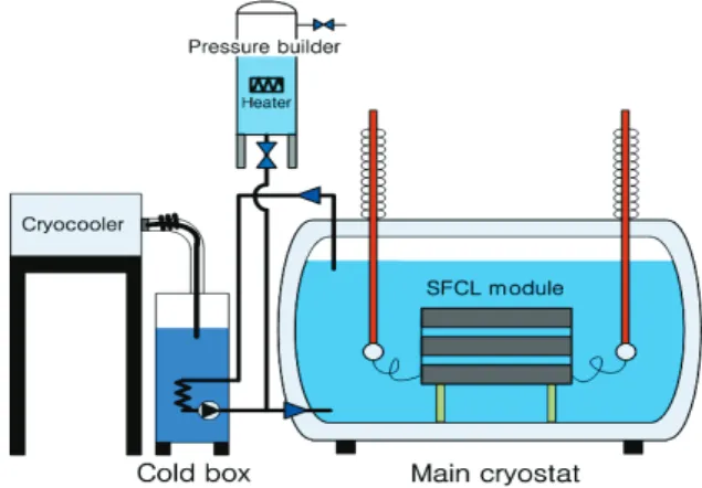
Fig. 1. Schematic diagram of the 154 kV SFCL system.
Cooling performance test of the superconducting fault current limiter
H. Yeom*, a, Y. J. Honga, S. Ina, J. Koa, H. B. Kima, S. J. Parka, H. Kimb, and H. R. Kimb
a H Korea Institute of Machinery & Materials, Daejeon, Korea
b Korea Electric Power Corporation Research Institute, Daejeon, Korea
(Received 11 October 2014; revised or reviewed 17 December 2014; accepted 18 December 2014)
Abstract
The superconducting fault current limiter (SFCL) is an electrical power system device that detects the fault current automatically and limits the magnitude of the current below a certain safety level. The SFCL module does not have any electrical resistance below the critical temperature, which facilitates lossless power transmission in the electric power system. Once given the fault current, however, the superconducting conductor exhibits extremely high electrical resistance, and the magnitude of the current is accordingly limited to a low value. Therefore, SFCL should be maintained at a temperature below the critical temperature, which justifies the cryogenic cooling system as a mandatory component. This report is a study which reported on the cooling system for the 154 kV-class hybrid SFCL owned by Korea Electric Power Corporation (KEPCO). Using the cryocooler, the temperature of liquid nitrogen (LN2) was lowered to 71 K. The cryostat was pressurized to 5 bars to improve the dielectric strength of nitrogen and suppress nitrogen bubble foaming during operation of SFCL. The SFCL module was immersed in the liquid nitrogen of the cryostat to maintain the superconducting state. The performance test results of the key components such as cryocooler, LN2 circulation pump, cold box, and pressure builder are shown in this paper.
Keywords: Cryogenic cooling, cryostat, pressure builder, SFCL, sub-cooled LN2
* Corresponding author: [email protected]
devices such as current limiters, cables [2, 3]. To acquire stable and efficient cooling capability utilizing sub-cooled nitrogen, we have thoroughly reviewed the thermodynamic characteristics and heat transfer characteristics of LN2.
Based on this knowledge, we determined the specification of the cryogenic cooler (SPC-04), the key component of the system, and then designed the rest of the system such as cold box, pressure builder, main cryostat (Fig. 1). The volume of the main cryostat was 30 m3, and it was filled with approximately 25,000 kg of LN2. In the cold box, the LN2 circulation pump (BNCP-64C), flow meters, hydro-cyclone used to filter out particles with diameter of 40 micrometers or more to prevent partial discharges under high electric voltage, cryogenic heat exchanger with capacity of 5 kW, which is used to cool the liquid nitrogen down to 71 K were installed. The pressure builder maintains the pressure of the main cryostat at 5 bars to enhance the insulation characteristics and to suppress nitrogen bubble generating during the current limiter operation [4-6]. It is automatically controlled by the values set based on the 2 kW heater and the solenoid valve. The SFCL module was cooled in the sub-cooled LN2 which maintained at 71 K and 5 bars. This paper presents the results of tests on the performances of the individual key components of the cooling system and overall cooling performance of the integrated system.
2. TEST AND EVALUATION
2.1. SAT (Site Acceptance Test) of Stirling Cryocooler The cryocooler is of the re-condensing type, model number SPC-4 manufactured by Stirling BV, Netherlands with cooling capacity of 4 kW at 77 K [7]. By controlling the rotating speed of the compressor motor and pressure of the helium gas in the range of 100% - 60 % individually as well as the overall cooling capacity could be controlled in the range of 100% - 36%. For the SAT, cooling capacity was tested by measuring the lowest achieved temperatures of the LN2 in the cold box corresponding to loads of 3.030, 3.245, 3.410, and 4.000 kW. The loads were adjusted by using the 4 kW electric heater installed in the cold box (Fig.
2). The results show that the capacity is 4.0 kW at 76 K and 3.5 kW at 71 K as shown in Fig. 3. The capacity results obtained were 9% - 10% lower than those obtained at the factory acceptance test (FAT) carried out at the cryostat only. Because of the external thermal loads caused by the addition of components such as pressure builder, circulation pipe lines on the top of the cold box.
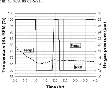
For the test on cooler capacity control, the load was gradually reduced from high to low as 3.250, 2.000, and 1.200 kW, with the helium pressure and rotating speed of the compressor motor monitored. The capacity was found to be controlled duly to maintain the set temperature (Fig.
4). The SAT and capacity control test confirm that the selected cryocooler, SPC-4, is adequate for the cryostat cooler for the 154 kV class SFCL needed for the study reported in this paper.
Cryocooler controller Vacuum pump
Liq./vapor line SPC-4(RL)
Cold box Pressure
builder VFD
Fig. 2. Site acceptance test.
Temperature (K)
66.0 68.0 70.0 72.0 74.0 76.0 78.0 80.0
Cooling capacity (W)
2000 2500 3000 3500 4000 4500 5000
FAT SAT
Fig. 3. Results of SAT.
Time (hr)
0.0 0.5 1.0 1.5 2.0 2.5 3.0 3.5 4.0
Temperature (K), RPM (%)
55 60 65 70 75 80 85 90 95 100 105
He gas pressure (bar)
10 12 14 16 18 20 22 24 26 28 30
RPM
Temp. Press.
Fig. 4. Cooling capacity control.
2.2. LN2 Circulation Pump
The circulation pump supplies the LN2 sub-cooled by the cooler to the main cryostat to cool the SFCL module.
The pump model BNCP-64C of Barber-Nicholas was selected. The motor is of the variable frequency drive type, with frequency range of 0 Hz - 100 Hz and maximum rotating speed of 5,700 rpm. The maximum allowable working pressure is 16.1 bars. The amount of heat load through the pump shaft and housing is a maximum of 30 W.
The overall pump performance was tested to see whether
Cooling performance test of the superconducting fault current limiter
the pump can sufficiently supply the cryogenic working fluid for cooling or not. The flow rate was measured while frequency was varied as shown in Fig. 5. Fig. 6 shows the change of flow rates for different rotation speeds, from which it is obvious that flow rate increases at a constant rate in proportion to the increase in rotation speed. The flow rate measured at 5,700 rpm was 0.48 kg/s. This flow rate corresponds to the cooling capacity of 1.9 kW at 5 bar, 71 K, and 2 K temperature difference. Considering the maximum cooling capacity 3.5 kW at 71 K, the cryogenic cooling system has extra cooling capacity in that state.
2.3. Hydro-cyclone
The hydro-cyclone collects the debris particles generated during welding, polishing and assembling for the main cryostat manufacture but are not properly removed.
The small-sized particles should be sufficiently removed.
Otherwise, they will not settle at the bottom but travel by floating in the cryostat and they may cause electrical discharge and break down the electrical insulation under a high-voltage. Fig. 7 shows the result of the numerical calculation of the pressure d drop across the cyclone as a flow rate. The pressure drop was approximately 6 kPa (0.06 bar) at a 0.4 kg/s, implying that the pressure drop is negligible.
Time (hr)
0.0 0.5 1.0 1.5 2.0 2.5 3.0 3.5
Mass flow rate (kg/s)
0.0 0.1 0.2 0.3 0.4 0.5 0.6
40 Hz (1 hr)
50 Hz (1 hr) 20/50/60 Hz
40/60/70/80/90/95 Hz
Fig. 5. Pump operation test.
Rotational speed (RPM)
0 1000 2000 3000 4000 5000 6000
Mass flow rate (kg/s)
0.0 0.1 0.2 0.3 0.4 0.5 0.6
Fig. 6. Mass flow rate according to RPM.
Mass flow rate (kg/s)
0.3 0.4 0.5 0.6 0.7
Pressure drop (kPa)
0.0 2.0 4.0 6.0 8.0 10.0 12.0 14.0 16.0 18.0 20.0
Fig. 7. Pressure drop according to mass flow rate.
2.4. Pressure Builder
The pressure builder maintains the internal pressure of the main cryostat at 5 bars to enhance the dielectric strength of LN2 and to suppress the foaming of nitrogen bubbles, which may occur during the operation of the SFCL.
Pressure control is achieved by turning on the 2 kW electric heater to evaporate the LN2 to raise the pressure and by the relief valve to lower the pressure. Fig. 8 shows the results of the performance test of the pressure builder with the cryostat isolated to check the heater and valve function. In accordance with the control signals, the pressure is correctly controlled at the set value with a period of approximately 10 minutes. If the pressure builder is connected to the main cryostat, however, the period changes due to the addition of heat loads associated with the main cryostat, pipe lines, pump and valves. The connection of the main cryostat and the pressure builder should be done when the internal pressures of both components reach 5 bars. To create the pressure in the main cryostat, it was filled with LN2 up to the 90% level of it, and LN2 was circulated through the use of the pump. The cooler turned on, so LN2 was cooled to about 75 K. During the pressure builder was made to have 5 bars, the main cryostat is pressurized directly using nitrogen gas through the separate pipe line.
Time (hr)
0.1 0.3 0.5 0.7 0.9 1.1 1.3 1.5
Pressure (bar)
4.90 4.92 4.94 4.96 4.98 5.00 5.02 5.04 5.06 5.08
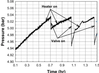
Heater on
Valve on
Fig. 8. Heater and valve operation test.
68
0.5 1.5 2.5 3.5 4.5 5.5
Time (hr)
0 10 20 30 40 50 60 70
Pressure (bar)
0.5 1.5 2.5 3.5 4.5 5.5
Pressure builder(PB)
Main cryostat
N2 gas pressurization
PB control
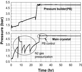
Fig. 9. Keep the design pressure test.
When both pressures were 5 bars, the flow loop between the pressure builder and the cryostat was connected. After connection the state of the main cryostat is maintained the design condition of 71 K, 5 bars stably in Fig. 9. As shown in the figure, heat balance was reached, with the operation condition maintained for more than 40 hours without the pressure relief valve of the pressure builder being operated.
2.5. Main Cryostat
The main cryostat contains sub-cooled liquid nitrogen at 71 K, 5 bars to cool the SFCL module. It consists of a two-layered configuration with the inner LN2 vessel and the outer vacuum chamber. The outer surface of the LN2 vessel is covered with multi-layer insulation to minimize the radiation heat. The plenum between the LN2 vessel and the vacuum chamber is kept in vacuum state to isolate the external heat load. The weight of the cryostat is approximately 45,000 kg in all including body, LN2, SFCL module, and bushing. The transient temperature distribution on the main cryostat and the cold box during the cooling process is shown in Fig. 10. As shown in the
Time (hr)
0 10 20 30 40 50 60 70
Temperature (K)
65 70 75 80 85
LN2 Return LN2 Supply Cold box
Fig. 10. Temperature profile of main cryostat.
figure, it took approximately 70 hours to lower the overall temperature of the main cryostat to 71 K, and the temperature difference between inlet and outlet was kept constantly at 2 K. LN2 was supplied to the bottom of the main cryostat and returned at the top. Thus, temperature of LN2 in vessel goes down.
from the bottom to the top of the main cryostat. As such, the temperature deviation at the point where the SFCL module is located is confirmed to be not bigger than 1 K.
3. SUMMARY
Performance tests have been carried out on the key components of the cooling system for the 154 kV class hybrid-type SFCL. The results confirm that the operational condition of 71 K, 5 bars can be stably supplied. Details of the test results on each component are as follows,
The cryocooler shows cooling capability of 4.0 kW @ 76 K, 3.5 kW @ 71 K. Likewise, smooth capacity control for load variation is confirmed to be feasible.
For the LN2 circulation pump, flow rate is 0.48 kg/s at 5,700 rpm, the maximum rotating speed.
The electric heater and valve used for pressure control of the pressure builder and the operational condition of the main cryostat is maintained for 40 hours or more without any valve operated.
It takes approximately 70 hours for the temperature of the LN2 in the main cryostat to reach 71 K. The temperature deviation at the mid-point where the SFCL module is located is confirmed to be 1 K or less.
ACKNOWLEDGMENT
This work was supported by a grant from the Power Generation & Electricity Korea government Ministry of Trade, Industry, and Energy.
REFERENCES
[1] O. B. Hyun, H. R. Kim, Y. S. Yim, J. Sim, K. B. Park, and I. S. Oh,
“Domestic Efforts for SFCL Application and Hybrid SFCL,”
Progress in Superconductivity, vol. 10, no.1, pp. 60-67., 2008.
[2] S. Cho, D. L. Kim, H. S. Yang, W. M. Jung, D. H. kim, H. R. Kim, and O. B. Hyun, “Experimental Investigation of the subcooled Liquid Nitrogen for Resistive Superconducting Fault Current Limiter,” Proceedings of the Korea Institute of Applied Superconductivity and Cryogenics Conference, pp. 332-334, Oct.
2003.
[3] Cryogenic Association of Japan, Handbook of Superconductivity and Cryogenics. p. 318, 1994.
[4] M. Blaz and M. Kurrat, “Studies of breakdowns in liquid nitrogen at different pressure between Rogoswki electrodes,” Phys. Proc., vol.
36, pp. 130-1336, 2012.
[5] J. Ko, H. Yeom, Y. J. Hong, H. Kim, S. J. Park, D. Y. Koh, and H. R.
Kim, “Study on thermal response to instantaneous heat generation in LN2 chamber for HTS-SFCL,” IEEE Trans. Appl. Supercond., vol. 23, no. 3, Article# 5603204, 2013.
[6] H. Kim, J. Y. Lee, H. R. Kim, S. E. Yang, S. D. Yu, W. S. Kim, O. B.
Hyun, J. Ko, and H. Yeom, “An effect of HTS wire configuration on
Cooling performance test of the superconducting fault current limiter
quench recovery time in a resistive SFCL,” IEEE Trans. Appl.
Supercond., vol. 23, no. 3, Article# 5604104, 2013. [7] http://www.stirlingcryogenics.com/products/Cryocoolers/1Stage-C ryocoolers/SPC4-Cryogenerator/
70