Vol.19, No.4, (2017), pp.1~11 https://doi.org/10.9714/psac.2017.19.4.001
```
1. INTRODUCTION
A superconducting fault current limiter (SFCL) is a power machine that limits the fault currents in a power grid.
SFCLs are considered as one of the most promising candidates for power application based on high temperature superconductors (HTS). Extensive research and development on HTS SFCL has been conducted worldwide [1-8]. Researchers have explored various SFCL models and produced more than 20 units operating at medium as well as transmission voltages. Most of them were installed in real grids and field-tested while supplying electrical power to customers. For these systems, a field test involves performing the proposed operation and commercial service in a real grid for a significant period of time. A field test is necessary to validate the feasibility of an SFCL. It includes installation and operation, trouble shooting, and maintenance, and fault current limitation upon fault in the real grid.
The first successful field test of an SFCL based on HTS was pioneered by ABB in 1996, who developed a 6.6-kV SFCL [9, 10]. The SFCL was installed in the auxiliary line of a hydroelectric power plant, and field-tested for one year.
Since then more than 20 SFCLs of various models have been built and installed at various locations in distribution and transmission grids. They were field-tested to prove their feasibility and current limiting capabilities. The field
tests provided instances of long-term operation as well as successful limitation of the real fault currents upon faults in the grids. The tests also went through various trouble shooting and maintenance, yielding valuable lessons in handling the new machine. Even with the track record of SFCL operation in the last 20 years, they are still not considered as fully commercialized till date because the field applications were performed in the research and development (R&D) environment. However, the recent activities in the private sector could be an indicator of their commercial application in the electric utility field.
In this review, we will focus on the field tests of SFCLs, rather than either researches or technological treatments of an SFCL. Consequently, of major interest is the status of more than 20 field test projects and applications of the SFCLs worldwide. Based on those tests, we will briefly discuss the trends in the SFCL types and the technical issues inherent to the SFCL technology associated with general applications. This review is based on public documents such as papers, articles, project reports, and documents available online.
2. SUPERCONDUCTING FAULT CURRENT LIMITER TECHNOLOGY
2.1. SFCL types
Various types of SFCLs have undergone the R&D stage.
Brief review of the field test and application of a superconducting fault current limiter
Ok-Bae Hyun*
SuperGenics, Changwon 51543, Korea
(Received 5 December 2017; revised or reviewed 14 December 2017; accepted 15 December 2017)
Abstract
This article reviews the recent activities of field testing and application of superconducting fault current limiters (SFCL) based on high-temperature superconductors (HTS). The review particularly focuses on the trends in the field tests in terms of the technical aspects and commercial activities of the SFCLs. Stimulated by the discovery of HTS, numerous research and development activities have been conducted worldwide for SFCLs operating from distribution voltages to transmission voltages. Different types of SFCLs have been developed and field-tested. Consequently, more than 20 field tests and applications have been performed on real grids worldwide while supplying electric power to the customers. These field tests have not only provided the track records of the operation experiences including the problems and maintenance during operation, but also proved their current limiting capabilities against real faults, rendering this new technology highly viable. Through these activities, the following trends in the status of field testing and application are observed. Resistive-type SFCLs with HTS-coated conductors were dominantly used in the most recent field tests. This implies that the resistive type is technically more mature than the other types. Bus-bar coupling and transformer feeders were the major application locations. It is of importance that most of the field applications were conducted as R&D projects.
A relevant change from the R&D stage to the application stage is shown as recently deployed SFCLs are expected to be under long-term operation and commercial service. Here, we review the installation of these SFCLs by substation. This review also discusses the recent activities for their commercial applications.
Keywords: superconducting fault current limiter, SFCL, field test, resistive type, bus-bar coupling, fault current
* Corresponding author: [email protected]
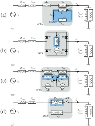
Fig. 1. Basic circuits of the SFCL types: (a) Magnetic shield type (shielded core type), (b) bridge type (electronic inductive, DC reactor, or rectifier type), (c) saturated iron-core type, and (d) resistive type. The grey and blue areas denote the SFCL system and superconducting parts, respectively. The diagrams represent single phase structures, although multiple variations exist for each type.
Among them, four types of SFCL structures have been successfully developed to be field-tested and applied: (1) magnetic shield type, (2) bridge type, (3) saturated iron-core type, and (4) resistive type. Figure 1 shows the basic circuits of the four types of SFCLs. Multiple variations of these four types are under research and development.
Details of the working principles of these types of SFCLs are widely reported in articles. Each of these SFCLs has its own merits and de-merits. We will discuss the technical issues associated with the application of the different SFCL types later in another section of this article.
Early successes in the SFCL developments were obtained with the magnetic shield type and bridge type.
More successful developments and field tests were achieved with the saturated iron-core type. However, most of the recent trials of SFCL field test have been performed with the resistive-type SFCL. This is indicative of the technological advantages of the resistive type over the other types in terms of the structure and effectiveness.
3. FIELD TESTS AND APPLICATIONS OF SFCL The first field test of an SFCL based on an HTS was conducted in 1996 at the auxiliary power grid of a
hydroelectric power plant in Switzerland [9]. Since then more than 20 field tests have been performed. In this section, we will review the tests by country and chronologically.
3.1. Switzerland
• Löntsch, NOK power plant
The first of field test of an SFCL based on an HTS was pioneered by ABB in cooperation with the Swiss utility NOK and with financial support from the Swiss Utility Study Fund (PSEL) [9-11]. ABB successfully developed a 6.6-kV magnetic shield type SFCL (1.2 MVA), which utilized stacked Bi2212 bulk tubes. The machine was installed to protect the auxiliary line of an NOK hydroelectric-power plant in Löntsch, Switzerland, for which a one-year endurance test was performed from November 1996. The test was expected to provide insight on the cooling system and possible fatigue aging of the HTS. After six months of testing, no major problems were encountered, and no fault occurred during the test.
3.2. United States of America
Four field tests were performed in the USA: two were sponsored by the Department of Energy (DOE), one by the New York State Energy Research and Development Authority (NYSERDA), and one by a manufacturer.
• General Atomics and Southern California Edison The first pre-commercial SFCL in the USA was developed by General Atomics (GA) and the Los Alamos Nation al Laboratory (LANL) with support from the DOE.
It was a bridge type with a rated voltage and current of 15 kV and 1200 A, respectively [12-14]. The SFCL unit was equipped with three of the largest Bi-2223 coils of the world at that time. This machine was installed in June 1999 at the Center substation of the Southern California Edison (SCE) grid. During high-voltage testing, each of the three single-phase units experienced a voltage breakdown, one externally and two internally [14]. After redesigning the structure, a high-voltage test as well as load and short-circuit tests were performed for the single-phase unit operating at the LANL 13.7-kV substation.
• Avanti circuit and Shandin substation, SCE
The second pre-commercial SFCL of the saturated iron-core type was developed by Zenergy Power. The voltage and current ratings were 15 kV and 1200 A, respectively. The SFCL used one HTS coil for three phases.
It generated a strong magnetic field to saturate the six iron cores, each of which carried one AC line coil. The SFCL enabled the first successful field test in the USA at Avanti circuit, Shandin substation of the SCE grid in March 2009 [15]-[20]. This SFCL experienced multiple fault events in the grid during operation, and as designed, successfully limited the fault currents.
• Knapps Corners substation, Central Hudson Gas &
Electric
The third SFCL field test was performed by Applied Materials (AMAT). AMAT developed a resistive type
SFCL (ratings 13.8 kV and 1000 A), and installed it in its Silicon Valley corporate grid for a one-year service starting from July 2013 [21].
Next, AMAT built and installed a resistive type SFCL in the Knapps Corners substation of Central Hudson Gas &
Electric grid, Poughkeepsie, NY. In contrast with other field tests, this SFCL bypassed the neutral grounding reactor (NGR) of a main transformer (115 kV, 14.4 kV), treating the line-to-ground faults [22, 23]. This project was sponsored by NYSERDA.
The SFCL system was was operated for more than three years under various environmental conditions including temperature extremes and heavy snow [24]. Late 2017, when the machine was shut down, the system was reported to have responded to 31 fault currents [25].
3.3. Germany
Germany is active in both the manufacturing and application of SFCLs. Two manufacturers, Nexans Superconductors and Siemens, have supplied five SFCLs for the field tests in Germany.
• Netphen substation, RWE with CURL10
The first field test was the CURL10 project. Nexans Superconductors developed a 10-kV, 10-MVA resistive type SFCL using Bi2212 bulk. It was installed in a bus-tie position in the RWE grid of the Netphen substation and field-tested for one year, starting from April 2004 [26-30].
No fault conditions were reported during the testing period, but a low-magnitude single-phase fault occurred, which could not quench the superconducting elements.
• Boxberg with Vattenfall and ENSYSTROB Subsequent SFCL tests were performed at the Boxberg power plant of Vattenfall. Nexans Superconductors supplied an SFCL with ratings of 12 kV and 800 A. It was installed in a feeder to a rebound hammer mill and underwent testing by daily routine operation from November 2009 to October 2010 [31-34]. During operation, this system encountered two occurrences of power outages caused by ancillary part issues, the LN2 level sensing and temperature of the vacuum pumps. In both cases, the system was disconnected from the grid and brought back to operation shortly after resolving the problems [33].
The objective of ENSYSTROB, a government-funded project, was to substitute the Bi2212 superconductors of the SFCL of Vattenfall in Boxberg with components based on HTS coated conductors, to achieve low AC loss and faster fault current limitation [35,36]. All the non-superconducting parts such as the cryogenic system and ancillary equipment kept unchanged. A successful factory test was completed in September 2011, followed by implementation in the SFCL system of Vattenfall for a one-year field test.
• AmpaCity and Hercules substation, RWE
Another SFCL field test program is the Ampacity project, in which an HTS cable and SFCL combined system was
installed at the Hercules substation in the inner city of Essen [37-41]. The SFCL was connected in series with the HTS cable, having the same current and voltage ratings of 10 kV and 2300 A, respectively. Nexans Superconductors was assigned with the task of manufacturing, installing, and commissioning the HTS cable and SFCL combined system.
This system was installed in October 2013 and put into operation from April 2014 for a two-year field test. In the project, the official target for the non-operational time was four hours or less. After half a year of operation, the system was found to be highly reliable with only two or three hours of non-operational time. The system operation was extended beyond the initial project period, aiming for a long-term operation
• Lechhausen substation, Statwerke-Augsburg The most recent progress in SFCL field testing has been initiated by Statwerke-Augsburg and Siemens under the project ASSiST. This project shows how decentralized feed-in systems can be safely integrated into a medium-voltage network [42]. Here, a 10-kV SFCL protects the distribution grid between Augsburg and a municipal utility company, MTU Onsite Energy manufacturing a combined heat and power (CHP) plant [43]. Siemens developed [44-46] and installed the SFCL at the Lechhausen substation of the Statwerke-Augsburg grid that started operating from March 2016 [42].
The test was to confirm not only the functionality and reliability, but also the operational experience in regard to the economic aspect. The field test may continue until 2017.
However, this SFCL is expected to be in long term operation as contracts are arranged for permanent installation [46].
3.4. United Kingdom
The United Kingdom (UK) is very active in applying SFCLs, owing to its shift toward a low carbon-based economy. Here, we discuss the five field tests of SFCLs
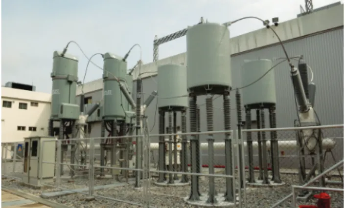
Fig. 2. Main part of the SFCL at Statwerke-Augsburg [43].
(Courtesy by Siemens.)
conducted in the UK. All of them were supported by the Low Carbon Network Fund (LCNF) through the Innovation Funding Incentive [47-50]. A consortium comprising of Applied Superconductor Limited (ASL) and three distribution network operators deployed three pilot SFCLs, which were installed at the Bamber Bridge, Ainworth Lane, and Scunthorpe substations. In addition, Western Power Distribution (WPD) supported two SFCLs for field application at the Chester Street and Bournville substations in the Birmingham area [51, 52].
• Bamber Bridge substation, Electricity North West (ENW)
The first of the three SFCLs by ASL and consortium was a resistive type SFCL, with 12 kV and 100 A ratings.
Nexans Superconductors supplied the SFCL, which consisted of Bi2212 tubes in a bifilar design. It was installed in October 2009 in the 11-kV bus section of the Bamber Bridge substation of the ENW network near Lancashire. It was energized for one year and carried load currents for approximately four months [47, 53, 54].
• Ainworth Lane substation, Scottish Power The second resistive SFCL, rated 11 kV and 400 A, was commissioned at the Ainsworth Lane substation in Liverpool in the Scottish Power grid in August 2012. The SFCL was installed in the bus-section location [47]. This SFCL, however, was only in normal operation for approximately 12 months, whereas it was operational in situ for approximately 20 months, due to the technical problems associated with the cryogenic system [55].
• Scunthorpe, Northern Power Grid (Formally CE Electric)
The third trial of SFCL in the UK was a saturated iron-core type SFCL developed by ASL. It was installed in the bus-section location of the Scunthorpe substation of the Northern Power Grid in Lincolnshire. The SFCL, rated 11 kV and 1250 A, was in a live-grid service from July 2012, and it operated for two years, which ended in 2014 [47].
The SFCL experienced a three-phase fault with a successful current limitation [53].
• WPD – Chester Street and Bournville, Birmingham Two more trials of SFCL applications were initiated by WPD. Both were supplied by Nexans Superconductors, and installed in the bus-section location of the WPD grid.
[51], [56-58].
One SFCL unit, rated 12 kV and 1600 A, was installed in the Chester Street substation. Another unit, rated12 kV and 1050 A, was installed in the Bournville substation in Birmingham. The Chester Street SFCL was put into service from November 2015, whereas the Bournville SFCL started service from March 2016. Both machines encountered temporary stops owing to the problems of the cooling system in the early stage of operation. They were re-connected after repairs [59].
Both are expected to complete a two-year field testing.
They are projected to be operated for commercial service after the test.
3.5. Italy, Spain, and other parts of Europe
• San Diogini, A2A Reti Elettriche, Italy
The Italian SFCL program was conducted by Ricerca sul Sistema Energetico (RSE). A 9-kV, 3.4-MVA SFCL was developed and installed to protect a distribution feeder in a medium voltage substation, San Dionigi, in the Milan distribution grid belonging to the utility company, A2A Reti Elettriche S.p.A. The SFCL was commissioned on March 2012 and field-tested until June 2014. This SFCL experienced an artificial three-phase fault, with a prompt limitation of the fault current by a factor of approximately 2.
The second phase test with an upgraded 15.6-MVA unit is underway [60-63].
• ECCOFLOW project (Endesa & VSA)
This was an EU project for the development and testing of a 24-kV, 1-kA SFCL based on HTS coated conductors [64, 65]. It aimed to becoming the first permanent grid installation. Two installation sites were proposed: the Endesa grid in Spain, and the Kosice of the VAS grid in Slovakia. The machine was successfully designed and manufactured by Nexans Superconductors [66].
The SFCL was installed in the bus-bar coupling location of the San Juan de Dios substation in the Endesa grid, Palma de Mallorca, Spain. The live grid operation was scheduled from October 2013 for six months [67].
Thereafter, it was to be shifted to the VSA network in Košice, Slovakia [68, 69].
3.6. China
• Gaoxi and Baiyin
The Chinese Academy of Sciences (CAS) initiated the first SFCL development. The SFCL was the bridge type, with ratings 10.5 kV and 1500 A and three phases. It was first installed in the Gaoxi substation, Hunan, China, and operated for 11000 hours. Thereafter, it was shifted to the HTS power substation to be integrated with an HTS cable and a superconducting magnetic energy storage in Bayin, Gansu for further operation [70-72].
• Puji substation, China Southern Power Grid Innopower successfully developed a saturated iron-core type SFCL, operating at 35 kV. The characteristic features of the SFCL included a power electronic switch and a piezo resistor, which are essential parts to de-energize an HTS coil. The SFCL was installed to protect a feeder line at the Puji substation in the China Southern Power Grid, and was commissioned on December 2007 for four years of operation [73-77]. Since being commissioned, one minor short circuit event has occurred, for which the DC magnetization switch was safely switched as designed.
However, a complete performance evaluation was not available due to small fault currents.
• Schegezhuang substation, State Grid of China Following the 35-kV SFCL, Innopower continued to develop a 220-kV (300 MVA) saturated iron-core type SFCL under the government support through National 863 Plan. After completing the factory tests, the SFCL was installed at the Shigezhuang substation in the Chinese State
grid in Tianjin, China. It began operation since June 2012, and was planned for a three-year live grid operation to test its feasibility [78-81].
3.7. Korea
Supported by 10 years of SFCL development efforts [82], KEPCO Research Institute (KEPRI), Korea Electric Power Corporation (KEPCO), launched a project for SFCL field testing. LS Industrial Systems (LSIS) manufactured a resistive type SFCL rated 22.9 kV and 630 A [83-88]. It was installed to protect a feeder line at the Icheon substation of the KEPCO grid. Prior to energizing, the SFCL was pre-tested for more than five months. It was energized on August 2011, and started its live-grid service for more than 1.5 years. Two fault events occurred on the line, but the SFCL limited the fault currents successfully as designed [87].
3.8. Tokyo Gas
Toshiba developed a 6.6 kV resistive type SFCL. The SFCL was primarily comprised of sets of current limiting coils of coated conductors operating in subcooled liquid nitrogen. The SFCL was installed between a gas engine generator and utility grid at the Senju Techno station, Tokyo Gas in early 2008, followed by a consecutive operation. It was operated on a daily start-and-stop basis [89-91].
3.9. Un-completed trials of field testing
There were projects aimed at development and field tests, but did not result in live-grid operation. These are summarized by the location of the SFCL installation in the grid.
An example is the DOE-sponsored 138-kV SFCL project led by American Superconductors and Siemens. As of 2011, when the project was stopped [1], a single-phase prototype of a resistive SFCL operating at 138 kV was successfully built and tested [92]. A three-phase unit was planned to be installed at the Devers substation in the
Fig. 3. SFCL of 22.9 kV at the Icheon substation, which performed a continuous operation for two years [86].
(Courtesy by KEPRI.)
115-kV SCE power network near Riverside, California, where it was supposed to service a bus tie.
Another case is the 138-kV saturated iron-core type SFCL of Zenergy, which was eventually not completely developed. It was to be installed at the Tidd substation of the American Electric Powers located near Steubenville, Ohio in 2012. The installation was planned to be on the low side of the 345-kV to-138 kV transformer to protect the 138-kV feeder [16].
3.10. Commercial application, Glow Energy, Thailand In April 2015, AMAT announced that it received orders for two transmission-class SFCLs from Glow Energy, an independent power producer (IPP) in Thailand. As the utility company planned to connect the additional generation capacity to the 115-kV line, the increased fault current was to be reduced prior to coupling with the power grid [25].
AMAT manufactured two sets of resistive type SFCLs with ratings of 115 kV and 900 A [93-95]. They were installed at the secondary side of the transformers at Map Ta Phut Industrial Estate of Glow Energy grid in Rayong, Thailand, and commissioned on July 2016. This may be the first commercial activity of an SFCL application, as the SFCL installation and operation were conducted in the private sector.
3.11. Ongoing projects and further activities
One of the trials of SFCL in the UK sponsored by the LCNF is to apply a 33-kV unit at the Jordanthorpe substation of the Northern Power Grid in South Yorkshire.
After ASL, ASG Power Systems assumed the development of a 35 kV saturated iron-core type SFCL. It was planned to be installed at the tail side of a 275-kV, 33-kV transformer at the substation in 2017 [96, 97].
KEPRI has developed a single-phase prototype of the resistive SFCL with ratings of 154 kV and 2000 A [98].
The SFCL was installed at the Gochang Power Testing Center, KEPCO, for various performance tests including a short-term connection to the 154 kV line [99].
Manufacturing and field test of a three-phase unit are under planning.
Fig. 4. SFCL of 115 kV under commercial service at Glow Energy. (Source: Applied Materials, Inc.)
Fig. 5. Prototype of the 154 kV SFCL by KEPRI [99].
(Courtesy by KEPRI.)
The most recent activity in the SFCL application is the
SuperOx project, through which UNECO, a utility company in Moscow, Russia, is aiming for a commercial application of an SFCL. In this project, a 220 kV SFCL is used to protect the network coupling between the substations in the UNECO grid. A single phase prototype is under development by SuperOx. A three-phase unit is planned to be installed at the Mnevniki substation for in-grid operation in 2018 [100, 101]. This project deserves attention in terms of the commercialization since it was planned and carried out in the private sector.
4. APPLICATION TREND and DISCUSSION As described in the previous section, since 1996, there have been more than 20 field applications. These are summarized in Table 1 chronologically, instead of by country.
TABLE1
SUMMARY OF THE SFCLFIELD TESTS AND APPLICATIONS. Installation site Project or Financial
Support (Utility) Manufacturer
(Type) Ratings Field test (FT) or live-grid operation period V(kV) I(A)
Löntsch, Switzerland PSEL (NOK) ABB (MS) 10.5 66 Power plant grid (1996 - 1997, six months) SCE Center SS, LA,USA SPI-DOE (SCE) GA (BG) 15 1200 SCE grid (operation test N/A)
Nephen SS, Germany CURL10 (RWE) Nexans (R) 10 800 Bus-tie (Apr. 2004 - Mar. 2005)
Baiyin SS, Gansu, China MOST, China (N/A) CAS (BG) 10.5 1500 Transformer (secondary) (Feb. 2011 - Mar. 2015) Tokyo Gas, Japan NEDO (Tokyo Gas) Toshiba (R) 6.6 72 IPP connection (Jan. 2008 -, N/A)
Puji SS, Kunming, China CMST (Southern China Power Grid) Innopower
(SI) 35 1500 Outgoing feeder (Feb. 2008 - more than four years) Shandin SS, LA, USA CEC Avanti & DOE
(SCE) Zenergy (SI) 15 2000 Outgoing Feeder (Mar. 2009 - Oct. 2010) Bamber Bridge,
Lancashire, UK IFI-LCNF (ENW) Nexans (R) 11 100 Busbar coupling (Oct. 2009 - Jun. 2010) Boxberg power plant,
Germany Vattenfall (Vattenfall) Nexans (R) 12 800 Outgoing feeder (power plant grid) (Nov. 2009 - Oct. 2010) Boxberg power plant,
Germany ENSYSTROB
(Vattenfall) Nexans (R) 12 800 Outgoing feeder (power plant grid) (Oct. 2011 -, one year) Icheon SS, Korea GENI (KEPCO) LSIS (R) 22.9 630 Outgoing feeder (Aug. 2011 - Jan. 2013) Ainsworth Lane,
Liverpool, UK IFI-LCNF (Scottish
Power) Nexans (R) 11 400 Busbar coupling (Aug. 2012 - Mar. 2014) San Dionigi SS, Milano,
Italy RSE (A2A) RSE (R) 9 (3.4 MVA) Feeder protection (Mar. 2012 - Jun. 2014) Scunthorpe SS, North
Lincolnshire, UK IFI-LCNF (Northern
Power Grid) Zenergy, ASL
(SI) 11 1250 Transformer (secondary) (Aug. 2012 - 2014) Shegezhuang SS, Tianjin,
China 863 plan, China
(Chinese State Grid) Innopower
(SI) 220 800 Transformer (primary) or Network coupling (Jun. 2012 -, three year operation planned.) San Juan de Dios, Palma
de Mallorca, Spain ECCOFLOW (Endesa) Nexans (R) 24 1005 Bus-tie (N/A, Planned Oct. 2013 -, for six months) AMAT, Santa Clara, USA AMAT (AMAT) AMAT (R) 15 1000 Local grid protection (Jul. 2013 - N/A)
Hercules SS, Essen,
Germany Ampacity (RWE) Nexans (R) 12 2300 HTS cable protection (Mar. 2014 -, two year field test, operation term extended) Knapps Corner SS,
Poughkeepsie, NY, USA NYSERDA (Central
Hudson G&E) AMAT (R) 15 400 NGR (Jun. 2014 - Fall 2017) Chester street SS,
Birmingham, UK FlexDGrid (WPD) Nexans (R) 12 1600 Busbar coupling (Nov. 2015 -, two year FT & long term operation planned) Bournville, Birmingham
SS, UK FlexDGrid (WPD) Nexans (R) 12 1050 Busbar coupling (Mar. 2016 -, two year FT & long term operation planned) Lechhausen SS,
Augsburg, Germany ASSiST
(Stadtwerke-Augsburg) Siemens (R) 10 815 IPP (CHP) connection (Mar. 2016 - 2017 & long term operation planned) Map Ta Phut, Rayong,
Thailand N/A (Glow Energy) AMAT (R) 115 800 Transformer (secondary), two units (Jul. 2016 -, commercial service)
※ MS = Magnetic shield type, BG = Bridge type, SI = Saturated iron-core type, R = Resistive type, N/A = Not Available.
4.1. Application trend
Table 1 shows a clear trend in the SFCL types. It reveals that the resistive type is more preferred in the SFCL field applications than any other types. In particular, all the recent trials of the field tests in the last five years have been performed using the resistive type. Furthermore, as of 2017, those under operation are all resistive types. This implies that the resistive type has more technological advantages than the other SFCL types.
4.2. Technical issues
Early trials of the SFCL field tests include the magnetic shield type and bridge type SFCLs. The former was applied once, as can be noted from Table 1. Producing large-sized superconducting rings may be difficult. The latter was applied twice. The SFCL by GA had troubles not only in the large power electronic switches, but also in electrical insulation [13, 14]. These issues might deter further development of the SFCL types.
Saturated iron-core type SFCLs have been actively researched and developed, as summarized in Table 1. This type is particularly attractive because no line currents are carried to the superconductors. Here, it is important to protect the HTS coil from the induced current due to the abrupt change in the magnetic flux in the iron core upon fault. There are two approaches to prevent the HTS coil damage: (i) use a protection circuit that bypasses the induced current to external circuits and (ii) discharge the HTS coil in a few milliseconds. The former was used by Zenergy, ASL, and currently, ASG power Systems. The latter was developed by Innopower.
The protection circuit of ASG has not proven sufficiently [96, 97]. In fact, no further successful development and field-test was publicly reported after the 12-kV SFCL of ASL was installed at the Scunthorpe substation. However, the design of Innopower was technically viable, as proved by the 35-kV and 220-kV SFCLs as well as the recent validation test with a single-phase prototype operating at 500 kV [102]. This design requires actively-controlled circuits to discharge the HTS coil in a few milliseconds on encountering a fault [80].
Major technical complications in a resistive-type SFCL design are due to the structure that carries the line current directly through the superconductors. This causes technical problems in the electrical insulation at cryogenic temperatures, and requires bulky cryostats and a high cryogenic load. However, these technical issues can be solved, in principle, by adapting an insulation distance under a high pressure, a live-tank cryostat, or high-capacity cryocoolers. These lend the resistive type SFCL a technological maturity, leading to further field applications [103]. However, further technological development is necessary for cost reduction.
4.3. Field test locations
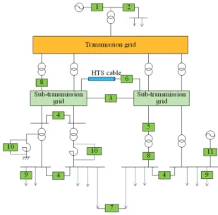
Figure 6 is a schematic of the potential locations for an SFCL. It is applicable wherever fault currents need to be reduced. Table 2 lists the installation locations of the SFCLs in Table 1. The numbers in brackets denote the
locations in Fig. 6. Un-completed trials of the field tests are included to examine the potential application sites. Table 2 reveals that the major applications of the SFCLs in the grid are for the protection of the bus-tie section and transformer feeder. Various other locations such as network coupling, IPP coupling, outgoing feeder, NGR, as well as combination with other HTS equipment such as an HTS cable are also feasible, as proven by the field tests and applications.
Fig. 6. Schematic of the potential SFCL locations [3].
TABLE2
APPLICATION LOCATIONS OF THE SFCLS.(NUMBERS IN BRACKETS ARE INSTALLATION LOCATIONS BASED ON FIG.6.)
Application Locations Installation site Generator feeder (1)
Power station auxiliaries (2) - Löntsch - Boxberg
Network coupling (3), Busbar coupling (4)
- Puji - Netphen - Bamber Bridge - Ainsworth Lane - San Juan de Dios - Chester Street - Bournville
- Devers, SCE (115 kV)*
- Mnevniki (220 kV)**
Protection of superconducting
equipment (6) - Hercules
Loop - Closing ring circuit (7)
Transformer (primary) (5) - Shigezhuang (220 kV)***
Transformer (secondary) (8)
- Gaoxi–Loudi & Baiyin - Shandin
- VSA (Eccowflow) - Scunthorpe - Map Ta Phut
- Jordanthorpe (33 kV)**
- Tidd, AEP (138 kV)*
Outgoing feeder (9) - Icheon - San Dionigi Shunting CLR / NGR (10) - Knapps Corner Coupling local generating units
(11) - Tokyo Gas (IPP)
- Lechhausen, Augsburg (CHP)
* Planned, but did not conclude with field test.
** On-going project.
** The SFCL is presumably at the primary side of a transformer (5) or network coupling location (3).
Early field tests were conducted primarily to prove the SFCL performance, as they were often installed at locations where the SFCLs were not entirely needed. This was a useful approach because the newly developed power device was not sufficiently reliable, therefore, could be disconnected safely from the grid in case of emergency.
For the recent SFCL installations in the last several years, the SFCL locations were carefully selected based on the fault current analysis. All the five substations in the UK trials were under excessive fault currents, so that fault current mitigation was demanded anyway [58]. In particular, fault current reduction was necessary for both Stadtwerke-Augsburg and Glow Energy due to the increased fault currents when additional generations were connected to the grid. The SFCLs may be a vital technology for current limitation in the next stage.
4.4. Economic feasibility
Early trials of a new technology used to depend on the technological completeness. In this view, it is logical that the technical maturity of the resistive type leads to the SFCL tests.
A resistive-type SFCL typically consists of cryostats containing HTS elements, refrigerators, current limiting reactors, and often circuit breakers, as shown in Fig. 1. This structure may demand a large foot print as well as high capital and operating cost. Table 1 highlights the aspects of economic issues in the SFCL field tests. As understood from the project names in Table 1, most of the field applications were conducted as R&D projects, in which public funds constitute a significant fraction of the budgets.
This implies that without significant cost reduction, an SFCL is too expensive to be applied generally [65].
5. SUMMARY
Since the introduction of HTSs, extensive R&D has been performed worldwide for SFCLs. Among them, more than 20 full-scale systems operating at both medium and transmission voltages were developed. Most of them were installed in a real grid and put into service. The field tests not only provided operational insights regarding the problems and maintenance during operation, but also proved their current limiting capabilities of real faults, rendering the new technology highly viable.
In this article, 23 field applications of SFCLs under live-grid operation were reviewed. The summary of the field applications is as follows:
• All the recently installed SFCLs are resistive type, implying that the resistive type is more technologically mature than the other types.
• The recent field tests were performed at locations where fault current mitigation was necessary anyway. The SFCLs may be a vital technology for the current limitation in the next stage.
• Majority of the selected locations of the SFCLs were bus-tie sections and transformer feeders. Various other
locations such as network coupling, IPP coupling, outgoing feeder, NGR, as well as combination with other HTS equipment were also feasible.
• The current limitation capability was proven by their limiting the currents of real faults in the grids during the tests.
• A high reliability with a cryogenic system is desired for long-time operation. Pre-operation before live-grid operation or redundant cryocoolers may be practical.
• Most of the field tests were conducted as R&D projects under the support of public funds. This implied that an SFCL is not economically feasible under the current technology, and efforts for reducing the cost are crucial for its general-purpose applications.
• A relevant change from the R&D stage to the application stage was shown, as recently deployed SFCLs are expected to be under long-term operation beyond the initial project period. Furthermore, as in Glow Energy and UNECO, the recent activities in the private sector could be indicators of the commercial application from the perspective of electric utility.
ACKNOWLEDGMENT
The author would like to thank Dr. Tabea Arndt, Mr.
James Kawski, and Dr. Young-Hee Han for allowing the use of the SFCL images.
REFERENCES
[1] S. Eckroad, Superconducting Fault Current Limiters, EPRI Technology Watch 2009 (1017793), EPRI, 2009.
[2] S. Eckroad, Superconducting Power Equipment, EPRI Technology Watch 2012 (1024190), EPRI, 2012.
[3] Mathias Noe and Michael Steurer, “High-temperature superconductor fault current limiters: concepts, applications, and development status,” Supercond. Sci. Technol., vol. 20, pp. R15 - R29, 2007.
[4] M. Noe, “Status of Development of Superconducting Fault Current Limiters (SCFCL) and Superconducting Cables,” presented at European Summer School on Superconductivity 2011, Harjattula Mansion, Turku, Finland, June 2011.
[5] Mathias Noe, “History, State‐of‐the‐Art and Perspectives of Superconducting Power Equipment,” presented at Superconductivity Centennial Conference, Hague, Netherlands, September 2011.
[6] A. M. Wolsky, HTS from precommercial to commercial - A roadmap to future HTS by the power sector, Implementing Agreement for a Cooperative Programme for Assessing the Impacts of High-Temperature Superconductivity on the Electric Power Sector, September 2013.
[7] Mathias Noe, “Superconducting Fault Current Limiters,” EUCAS Short Course Power Applications, Geneva, September 17, 2017.
[Online] Available: https://indico.cern.ch/event/626654/
attachments /1523851/2383317/Noe-FCL-2017-09-15.pdf.
[8] Roadmap Report for Superconducting Technology Industrialization, Internal Report, Korea Industries Confederation for Commercialization of Superconductivity, 2016. (In Korean.) [9] W. Paul, M. Lakner, J. Rhyner, P. Unternährer, Th. Baumann, M.
Chen, L Widenhorn, and A Guérig, “Test of 1.2 MVA high-Tc superconducting fault current limiter,” Supercond. Sci. Technol., vol. 10, pp. 914 - 918, 1997.
[10] W. Paul and M. Chen, “Superconducting control for surge currents,” IEEE Spectrum, pp. 49 - 54, May 1998.
[11] Makan Chen, Willi Paul, Martin Lakner, Lise Donzel, Markus Hoidis, Peter Unternaehrer, Reto Weder, and Michael Mendik, “6.4 MVA resitive fault current limiter based on Bi-2212 superconductor,” Physica C, vol. 372 - 376, pp. 1657 - 1663, 2002.
[12] E. Leung, et al., “Design & Development of a 15 kV, 20 kA HTS Fault Current Limiter,” 1EEE Trans. Applied Supercond., vol. 10, no. 1, pp. 832 - 835, 2000.
[13] Joseph Badin, High-Temperature Superconducting Electric Power Products, Energetics, Inc., January 2000. [Online] Available:
http://www.nrel.gov/docs/gen/fy00/supercon_products.pdf.
[14] Joseph A. Waynert, Heinrich J. Boenig, Charles H. Mielke, Jeffrey O. Willis, and Burt L. Burley, “Restoration and Testing of an HTS Fault Current Controller,” IEEE Trans. Applied Supercond., vol. 13, no. 2, pp. 1984 - 1987, 2003.
[15] Franco Moriconi, Francisco De La Rosa, Frank Darmann, Albert Nelson, and Larry Masur, “Development and Deployment of Saturated-Core Fault Current Limiters in Distribution and Transmission Substations,” IEEE Trans. Applied Supercond., vol.
21, no. 3, pp. 1288 - 1293, 2011.
[16] Keyue Smedley and Alexander Abravomitz, Development of Fault Current Technology - Prototyping, Laboratory Testing, and Field Demonstration, Final Project Report, prepared for California Energy Commission, June 2011.
[17] Albert Nelson, Larry Masur, Franco Moriconi, Francisco De La Rosa, and Detlev Kirsten, “Saturated-Core Fault Current Limiter Field Experience at a Distribution Substation,” CIRED 2011, paper 0680, Frankfrut, June 2011.
[18] A Kamiab, “SCE Limits Faults,” Transmission and Distribution, November 2011. [Online] Available: http://tdworld.com/
substations/sce-limits-faults.
[19] Zenergy, Fault Current Limiters, California Institute for Energy and Environment, 2010. [Online] Available: http://uc-ciee.org/
downloads/FCL-Overview.pdf.
[20] Alexander Abramovitz, Keyue Ma Smedley, Francisco De La Rosa, and Franco Moriconi, “Prototyping and Testing of a 15 kV/1.2 kA Saturable Core HTS Fault Current Limiter,” IEEE Trans. Power Delivery, vol. 28, no. 3, pp. 1271 - 1279, 2013.
[21] Kasegn Tekletsadik, “Fault Current Limiter Design and Application,” presented at Joint TNC CIGRE & IEEE PES Seminar on Understanding Superconducting Fault Current Limiters:
Design and Application, Bangkok, Thailand, September 29, 2015.
[22] Gunther Heinzel and Scott Nickerson, “Superconducting Fault Current Limiter at Knapps Corner Substation,” presented at The Resilient Smart Grid workshop, BNL, April 2015.
[23] John Davis, “Central Hudson testing device to reduce power losses,” Poughkeepsie Journal, July 18, 2014. [Online]. Available:
http://www.poughkeepsiejournal.com/story/news/2014/07/17/centr al-hudson-device-power/12813417/.
[24] “Thailand Engineers Tour Innovative Central Hudson R&D Project,” Press Release, Central Hudson, December 9, 2015.
[Online] Available: http://www.centralhudson.com/news/news/
dec9_2015.html.
[25] Albert Nelson, “Safe Guarding T&D Assets against Fault Currents,”
Applied Materials webinar. [Online] Available: http://tinyurl.com/
Safe-Guarding-TD-Assets-Asia.
[26] M. Noe, et al., “High voltage insulation and test of a 10 MVA resistive superconducting fault current limiter,” presented at SCENET Workshop Grenoble, March 15 - 16, 2004.
[27] Ronald Kreutz, Joachim Bock, Frank Breuer, Klaus-Peter Juengst, Martin Kleimaier, Hans-Udo Klein, Detlef Krischel, Mathias Noe, Ralph Steingass, and Karl-Heinz Weck, “System Technology and Test of CURL 10, a 10 kV, 10 MVA Resistive High-Tc Superconducting Fault Current Limiter,” IEEE Trans. Applied Supercond., vol. 15, no. 2, pp. 1961 - 1964, 2005.
[28] Joachim Bock, Frank Breuer, Heribert Walter, Steffen Elschner, Martin Kleimaier, Ronald Kreutz, and Mathias Noe, “CURL 10:
Development and Field-Test of a 10 kV/10 MVA Resistive Current Limiter Based on Bulk MCP-BSCCO 2212,” IEEE Trans. Applied Supercond., vol. 15, no. 2, pp. 1955 - 1960, 2005.
[29] Joachim Bock, “CONECTUS: Power Applications,” presented at ISIS 14, Tsukuba, October 28, 2005.
[30] M. Steurer, B. Marchionini, F. Darman, F. Lambert, and M. Noe,
“Towards a guide for testing emerging fault current limiters,”
CIGRE 2010, paper A3_307_2010, August 2010.
[31] Nexans, press release, Euronet, November 6, 2009. [Online]
Available: https://www.euronext.com/pt-pt/node/234140.
[32] R. Dommerque, S. Krämer, A. Hobl, R. Böhm, M. Bludau,J Bock, D. Klaus, H. Piereder, A. Wilson, T. Krüger, G. Pfeiffer, K. Pfeiffer and S. Elschner, “First commercial medium voltage superconducting fault-current limiters: production, test,”
Supercond. Sci. Technol., vol. 23, Art. ID. 034020, 2010.
[33] J. Bock, M. Bludau, R. Dommerque, A. Hobl, S. Kraemer, M. O.
Rikel, and S. Elschner, “HTS Fault Current Limiters – First Commercial Devices for Distribution Level Grids in Europe,” IEEE Trans. Appl. Supercond., vol. 21, no. 3, pp. 1202 - 1205, 2011.
[34] Mathias Noe, Joachim Bock, Achim Hobl, and Judith Schramm,
“Superconducting Fault Current Limiters - Latest developments at Nexans Superconductors,” presented at 10th EPRI Superconductivity Conference, Tallahassee, FL, USA, October 11-13, 2011.
[35] S. Elschner, A. Kudymow, Stefan Fink, Wilfried Goldacker, Francesco Grilli, Christian Schacherer, Achim Hobl, Joachim Bock, and Mathias Noe, “ENSYSTROB - Resistive Fault Current Limiter Based on Coated Conductors for Medium Voltage Application,”
IEEE Trans. Appl. Supercond., vol. 21, no. 3, pp. 1209 - 1212, 2011.
[36] S. Elschner, A. Kudymow, J. Brand, S. Fink, W. Goldacker, F. Grilli, M. Noe, M. Vojenciak, A. Hobl, M. Bludau, C. Jänke, S. Krämer, and J. Bock, "ENSYSTROB – Design, manufacturing and test of a 3-phase resistive fault current limiter based on coated conductors for medium voltage application,” Physica C, vol. 482, pp. 98 - 104, 2012.
[37] Frank Schmidt, “AmpaCity Project - Advanced Superconducting Cable System for Urban Power Supply,” presented at EPRI Superconductivity Conference, Houston, TX, USA, October 2013.
[38] Frank Merschel, “The AmpaCity Project,” T&D World Magazine, December 23, 2013. [Online] Available: http://tdworld.com/
overhead-distribution/ampacity-project.
[39] “The power supply of the future,” Power Engineering International, vol. 22(11), December 16, 2014. [Online] Available:
http://www.powerengineeringint.com/articles/print/volume-22/issu e-11/features/the-power-supply-of-the-future.html.
[40] Stemmle, “Advanced Superconducting 10 kV System in the City Center of Essen, Germany,” presented at EUCAS 2015. Lyon, France, September 6 - 10, 2015.
[41] Mark Stemmle, Frank Merschel, and Mathias Noe, “AmpaCity Project – Update on World’s First Superconducting Cable and Fault Current Limiter Installation in a German City Center,” CIRED 2015, paper 0678, Lyon, June 15 - 18, 2015.
[42] Franz Meyer, “Stadtwerke Augsburg testing superconducting fault current limiter,” BINE Information Service, March 21, 2016.
[Online] Available: http://www.bine.info/en/topics/news/
stadtwerke-augsburg-erproben-supraleitenden-strombegrenzer/fdf.
[43] Tabea Arndt, “Siemens’ first MV SFCL installed in a public grid – aspects from design to operation and operational experience,”
presented at EUCAS 2017, Geneva, September 2017.
[44] Siemens, “Siemens to use superconductors in building the power grid of the future in Augsburg,” Joint press release Siemens, Stadtwerke Augsburg, December 18, 2014.
[45] Thomas Janetschek, “ASSiST – Supraleitender Strombegrenzer,”
presented at ZIEHL V, Munich, March 16, 2016.
[46] Junior Isles, “Taking superconductors to the limit,” The ENERGY INDUSTRY TIMES, pp. 15, February 2015.
[47] Chris Waller & David Klaus, “Freeing up the Grid Speeding up the Connection of Renewable Generation with Low Cost Fault Current Limiter,” Renewable Energy World Europe, Vienna, June 2013.
[48] David Klaus, Adrian Wilson, Robert Dommerque, Joachim Bock, Darren Jones, Jamie McWilliam, and Alan Creighton, “Fault Limiting Technology Trials in Distribution Networks,” CIRED 2009, paper 0140, Prague, June 2009.
[49] Mathias Noe, Joachim Bock, Achim Hobl, and Judith Schramm,
“Superconducting Fault Current Limiters,” presented at Tenth EPRI Superconductivity Conference, October 11, 2011.
[50] David Klaus, Adrian Wilson, Achim Hobl, Joachim Bock, Darren Jones, Jamie McWilliam, Alan Creighton, Larry Masur, and Franco Moriconi, “Fault Limiting technologies in Distribution Networks,”
CIRED 2011, paper 0456, Frankfrut, June 2011.
[51] Beate West, Mark Stemmle, Jonathan Berry, and Achim Hobl,
“Commercial Application of Superconducting Fault Current Limiters in the Western Power Distribution Grid in the UK,”
CIRED 2015, paper 0985, Lyon, June 2015.
[52] Neil Murdoch, “Method Gamma: Fault level mitigation,” presented at Heat and Power for Birmingham - DNO Workshop on the Implementation of Enhanced Fault Level Assessment Processes, October 23, 2013.
[53] David Klaus, Jamie McWilliam, Joseph Helm, Chris Waller, Jonathan Berry, Mostafa Jafarnia, Darren Jones, Joachim Bock, and Achim Hobl, “Superconducting Fault current Limiters – UK Network Trials Live and Limiting,” in Proc. 22nd CIRED, paper 0285, pp. 1–4, Stockholm, 2013.
[54] Geraldine Bryson, “Superconducting Fault Current Limiters,”
dissemination day run by Northern Powergrid, October 2014.
[55] Innovation Funding Incentive Annual Report, SP Energy Power network, p. 37, March 2014.
[56] Jonathan Berry and Neil Murdoch, “Standardised Connections and the Economic Benefits of Fault Current Limiters on Distribution Networks,” CIRED 2015, paper 1129, Lyon, June 2015.
[57] “Nexans’ supplies two superconducting fault current limiters for permanent use on Birmingham's distribution network,” Press Release, Nexans, March 31, 2014.
[58] Project Progress Report: FlexDGrid, Reporting period: December 2014 to May 2015, Western Power Distribution, June 4, 2015.
[59] SDRC-9, Installation and Closed-Loop Tests of FLMs & FCLs, Western Power Distribution, December 13, 2016.
[60] Luciano Martini, Marco Bocchi, Massimo Ascade, Angelo Valzasina, Valerio Rossi, Cesare Ravetta, and Giuliano Angeli,
“Live-Grid Installation and Field Testing of the First Italian Superconducting Fault Current Limiter,” IEEE Trans. Appl.
Supercond., vol. 23, no. 3, Art. no. 5602504, 2013.
[61] L. Martini, M. Bocchi, G. Angeli, M. Ascade, V. Rossi, A.
Valzasina, C. Ravetta, S. Fratti, and E. Martino, “Live Grid Field-Testing Final Results of the First Italian Superconducting Fault Current Limiter and Severe 3-Phase Fault Experience,” IEEE Trans. Appl. Supercond., vol. 25, no. 3, Art. no. 5600405, 2016.
[62] G. Angeli, M. Bocchi, M. Ascade, V. Rossi, A. Valzasina, C.
Ravetta, and L. Martini, “Status of Superconducting Fault Current Limiter in Italy: Final Results From the In-Field Testing Activity and Design of the 9 kV/15.6 MVA Device,” IEEE Trans. Appl.
Supercond., vol. 26, no. 3, Art. no. 5600705, 2016.
[63] G. Angeli, M. Bocchi, M. Ascade, V. Rossi, A. Valzasina, and L.
Martini, “Development of Superconducting Devices for Power Grids in Italy: Update About the SFCL Project and Launching of the Research Activity on HTS Cables,” IEEE Trans. Appl. Supercond., vol. 27, no. 4, Art. no. 5600406, 2017.
[64] Luciano Martini, Mathias Noe, Pascal Tixador, Achim Hobl, and Marco Bocchi, “The ECCOFLOW Project: Design and Simulaitons Results of a Superconducting Fault Current Limiter for Operation in Electric Networks,” CIRED 2011, paper 1162, Frankfrut, June 2011.
[65] Antonio Colmenar-Santos, J.M. Pecharromán-Lázaro, Carlos de Palacio Rodríguez, and Eduardo Collado-Fernández, “Performance analysis of a Superconducting Fault Current Limiter in a power distribution substation,” Electric Power Systems Research 136, pp.
89 - 99, 2016.
[66] A. Hobl, W. Goldacker, B. Dutoit, L. Martini, A. Petermann, and P.
Tixador, “Design and Production of the ECCOFLOW Resistive Fault Current Limiter,” IEEE Trans. Appl. Supercond., vol. 23, no.
3, Art. no. 5601804, 2013.
[67] [Online] Available: http://catedraendesared.uib.es/index.php/
2-uncategorised?start=7.
[68] “SuperPower Wire Powers European Union ECCOFLOW Supercopnducting Fault Current Limiter,” press release, Superpower, September 2013. [Online] Available:
http://www.superpower-inc.com/content/superpower-wire-powers- european-union-eccoflow-superconducting-fault-current-limiter.
[69] Final Report Summary - ECCOFLOW (Development and field test of an efficient YBCO Coated Conductor based Fault Current Limiter for Operation in Electricity Networks), EU Community Research and Development Information Service, December 2015.
[70] D. Hui, et al., “Development and test of 10.5 kV/1.5 kA HTS fault current limiter,” IEEE Trans. Appl. Supercond., vol. 16, no. 2, pp.
687–690, 2006.
[71] L. Xiao, et al., “Development of the world’s first HTS power substation,” IEEE Trans. Appl. Supercond., vol. 22, no. 3, Art. no.
5000104, 2012.
[72] J. Zhang, et al., “Development, Updating and Long-Term Operations of a 10.5 kV HTS Fault Current Limiter,” J. Supercond.
Nov. Magn., vol. 27, pp. 2195, 2014.
[73] Y. Xin, et al., “Manufacturing and Test of a 35 kV/90 MVA Saturated Iron-Core Type Superconductive Fault Current Limiter for Live-Grid Operation,” IEEE Trans. Appl. Supercond., vol. 19, no. 3, pp. 1934, 2009.
[74] Y. Xin, J. Z. Wang, H. Hong, W. Z. Gong, J. Y. Zhang, X. Y. Niu, A.
L. Ren, D. J. Si, M. R. Zi, Z. Q. Xiong, and F. Ye, “Field Tests on a 35kV/90MVA Superconducting Fault Current Limiter,”
Proceedings of 2010 International Conference on Power System Technology (POWERCON), pp. 1 - 5, October 24 - 28, 2010.
[75] Jianzhong Wang, Jibin Cui, Zhiquan Xiong, and Meirong Zi, “The Research of Relationship between SICSFCL and Distance Relay Protection of Power Grid,” Journal of International Council on Electrical Engineering, vol. 2, no. 2, pp. 126 - 130, 2012.
[76] Y. Xin, H. Hong, J. Z. Wang, W. Z. Gong, J. Y. Zhang, A. L. Ren, M.
R. Zi, Z. Q. Xiong, D. J. Si, and F. Ye, “Performance of the 35 kV/90 MVA SFCL in Live-Grid Fault Current Limiting Tests,”
IEEE Trans. Appl. Supercond., vol. 21, no. 3, pp. 1294, 2011.
[77] Ren Anlin, Tian Mi, Zi Meirong, and Cui Jibin, “The Operation Research and Analysis of Superconductor Power Equipment at Yunnan Puji Substation,” Transactions of China Electrotechnical Society, vol. 27, no. 10, pp. 85 - 90, 2012. (In Chinese.)
[78] Y. Xin, W. Z. Gong, H. Hong, Y. Q. Gao, X. Y. Niu, J. Y. Zhang, Y.
W. Sun, A. L. Ren, H. Z. Wang, L. F. Zhang, Q. Li, Z. Q. Wei, L. Z.
Wang, J. B. Cui, G. J. Niu, and Z. Q. Xiong, “Development of a 220 kV/300 MVA superconductive fault current limiter,” Supercond.
Sci. Technol., vol. 25, Art. ID. 105011, 2012.
[79] Y. Xin, W. Z. Gong, Y. W. Sun, J. B. Cui, H. Hong, X. Y. Niu, H. Z.
Wang, L. Z. Wang, Q. Li, J. Y. Zhang, Z. Q. Wei, L. Liu, H. Yang, and X. H. Zhu, “Factory and Field Tests of a 220 kV/300 MVA Statured Iron-Core Superconducting Fault Current Limiter,” IEEE Trans. Appl. Supercond., vol. 23, no. 3, Art. no. 5602305, 2013.
[80] Xiaoye Niu, Zhili Chen, Haizhen Wang, Zhifu Chen, Lifeng Zhang, Guojun Niu, Hui Hong, and Ying Xin, “Structure and Performance Characteristics of Saturated Iron-core Superconducting Fault Current Limiter,” Journal of International Council on Electrical Engineering, vol. 4, no. 2, pp.146 - 150, 2014.
[81] H. Hong, B. Su, G. J. Niu, J. B. Cui, B. Tian, Q. Li, L. Z. Wang, Z.
H. Wang, K. Zhang, and Y. Xin, “Design, Fabrication, and Operation of the Cryogenic System for a 220 kV/300 MVA Saturated Iron-Core Superconducting Fault Current Limiter,” IEEE Trans. Appl. Supercond., vol. 24, no. 5, Art. no. 9002204, 2014.
[82] O.-B. Hyun, K.-B. Park, J. Sim, H.-R. Kim, S.-W. Yim, and I.-S. Oh,
“Introduction of a hybrid SFCL in KEPCO grid and local points at issue,” IEEE Trans. Appl. Supercond., vol. 19, pp. 1946 - 1949, 2009.
[83] G.-H. Lee, K.-B. Park, J. Sim, Y.-G. Kim, I.-S. Oh, O.-B. Hyun, and B.-W. Lee, “Hybrid superconducting fault current limiter of the first half cycle non-limiting type,” IEEE Trans. Appl. Supercond., vol.
19, no. 3, pp. 1888 - 1891, 2009.
[84] Min Jee Kim, Gyeong-Ho Lee, Seung-Hyun Bang, Hae Yong Park, Wonjoon Choe, Jungwook Sim, Seog-Won Lee, Young-Geun Kim, and Hye-Rim Kim, “The Application of Fault Current Limiter at Icheon substation in Korea,” 2011 1st International Conference on Electric Power Equipment – Switching Technology, Xian, China, 2011.
[85] Seun Ryul Lee, Jae-young Yoon, Byeongmo Yang, and Byongjun Lee, “Specifications of the 22.9 kV SFCL Considering Protection Systems in Korean Power Distribution System,” IEEE Trans. Appl.
Supercond., vol. 22, no. 3, Art. no. 5602404, 2012.
[86] Hye-Rim Kim, Seong-Eun Yang, Seung-Duck Yu, Heesun Kim, Woo-Seok Kim, Kijun Park, Ok-Bae Hyun, Byeong-Mo Yang, Jungwook Sim, and Young-Geun Kim, “Installation and Testing of SFCLs,” IEEE Trans. Appl. Supercond., vol. 22, no. 3, Art. no.
5602704, 2012.
[87] Hye-Rim Kim, Seung-Duck Yu, Heesun Kim, Woo-Seok Kim, Seong-Eun Yang, Ji-Young Lee, and Ok-Bae Hyun,
“Demonstration of a Superconducting Fault Current Limiter in a Real Grid,” IEEE Trans. Appl. Supercond., vol. 23, no. 3, Art. no.
5603604, 2013.
[88] Hye-Rim Kim, Seong-Eun Yang, Seung-Duck Yu, Heesun Kim, Byung-Jun Park, Young-Hee Han, Kijun Park, and Jaeun Yu,
“Development and Grid Operation of Superconducting Fault Current Limiters in KEPCO,” IEEE Trans. Appl. Supercond., vol.
24, no. 5, Art. no. 5602504, 2014.
[89] T. Yazawa, K. Koyanagi, M. Takahashi, K. Toba, H. Takigami, M.
Urata, Y. Iijima, T. Saitoh, N. Amemiya, Y. Shiohara, and T. Ito,
“Development of 6.6 kV/600 A superconducting fault current limiter using coated conductors,” Physica C, vol. 469, pp. 1740 - 1744, 2009.
[90] [Online] Available: http://www.nedo.go.jp/content/100096722.pdf.
[91] [Online] Available: http://www.istec.or.jp/fruit/news-pdf/
H20-1-29.pdf.
[92] Hans-Peter Kraemera, Wolfgang Schmidta, Hong Caib, Bruce Gambleb, David Madurab, Tim MacDonaldb, Joe McNamarab, Walther Romanoskyb, Greg Snitchlerb, Nicolas Lallouetc, Frank Schmidtd, and Syed Ahmed, “Superconducting Fault Current Limiter for Transmission Voltage,” Physics Procedia, vol. 36, pp.
921 - 926, 2012.
[93] “Applied Materials Receives Order for Two Transmission-Class Superconducting Fault Current Limiters,” press release, Applied Materials, April 15, 2015. [Online] Available:
http://en.acnnewswire.com/press-release/english/21682/applied-m aterials-receives-order-for-two-transmission-class-superconducting -fault-current-limiters.
[94] Kasegn Tekletsadik, “Fault Current Limiter,” Joint TNC CIGRE &
IEEE PES Seminar on Understanding Superconducting Fault Current Limiters: Design and Application, Thailand, September 29, 2015.
[95] [Online] Available: http://www.appliedmaterials.com/files/
generation.pdf.
[96] A. Wilson and D Klaus, Superconducting Fault Current Limiter, 33kV Network Impact Report, ASL, March 2011.
[97] Antonio Pellecchia, David Klaus, Giovanni Masullo, Roberto Marabotto, Antonio Morandi, Massimo Fabbri, Chris Goodhand, and Joseph Helm, “Development of a Saturated Core Fault Current Limiter With Open Magnetic Cores and Magnesium Diboride Saturating Coils,” IEEE Trans. Appl. Supercond., vol. 27, no. 4, Art.
no. 5601007, 2017.
[98] Heesun Kim, Young Hee Han, Seong-Eun Yang, Seung-Duck Yu, Byung Jun Park, Kijun Park, Jaeun Yoo, Hye-Rim Kim, Sehwan In, Yong Joo Hong, and Hankil Yeom, “Development and Test of a Cooling System for a 154 kV Superconducting Fault Current Limiter,” KEPCO Journal on Electric Power and Energy, vol. 1, no.
1, pp. 141 - 144, 2015.
[99] Young-Hee Han, Hye-Rim Kim, Seong-Eun Yang, Heesun Kim, Byung-Jun Park, Jaeun Yu, S. In, Y. J. Hong, and H. Yeom,
“Development and long term operation of a 154 kV SFCL,”
Progress in Superconductivity and Cryogenics, submitted for publication.
[100] [Online] Available: http://www.superox.ru/upload/FCL-full -information.pdf.
[101] M. Moyzykh, D. Sotnikov, D. Gorbunova, and S. Samoilenkov,
“Superconducting Fault Current Limiter for Moscow 220 kV City Grid,” presented at EUCAS 2017, paper 1L01-02, September 2017.
[102] [Online] Available: http://www.csg.cn/index/jdxw/201707/
t20170721_158718.html.
[103] J. Bock, A. Hobl, J. Schramm, S. Krämer, and C. Jänke, “Resistive Superconducting Fault Current Limiters Are Becoming a Mature Technology,” IEEE Trans. Appl. Supercond., vol. 25, no. 3, Art. no.
5600604, 2015.
![Fig. 2. Main part of the SFCL at Statwerke-Augsburg [43].](https://thumb-ap.123doks.com/thumbv2/123dokinfo/5237234.623915/3.892.531.734.796.1104/fig-main-sfcl-statwerke-augsburg.webp)
![Fig. 5. Prototype of the 154 kV SFCL by KEPRI [99].](https://thumb-ap.123doks.com/thumbv2/123dokinfo/5237234.623915/6.892.86.428.122.346/fig-prototype-kv-sfcl-kepri.webp)