Vol.19, No.4, (2017), pp.40~44 https://doi.org/10.9714/psac.2017.19.4.040
```
1. INTRODUCTION
Eco-friendly distributed power sources such as photovoltaic and wind power generation are increasing to address environmental problems and the problems of finite oil resources. To accelerate the application of such distributed power sources, long-distance transmission should be possible and connection to the existing grid must be easy. When the current AC grid is connected to distributed power sources, however, frequency as well as applied voltage must be considered. In addition, in the case of AC transmission, significant power loss occurs due to the frequency component for long-distance transmission.
When the DC grid and the distributed power sources are connected, however, the current can be conducted up to the capacity of the transmission line and long-distance transmission is possible. Furthermore, the number of power conversion devices can be reduced when distributed power sources are connected, thereby minimizing power loss [1].
Despite such advantages, the DC grid has not been applied to the actual grid yet. The biggest reason is that the safety of the DC grid has not been secured yet. The most representative protection device in securing the safety is a circuit breaker. As the DC grid does not have a natural zero point, interruption leads to a significant arc [2]. This may result in interruption failure and cause damage due to the
fault and fire of the power supply devices. Furthermore, the blackout phenomenon of the entire grid may occur.
In this study, the previously proposed transformer superconducting fault current limiter (TSFCL) interruption system was applied for the DC fault current interruption. At first, the TSFCL interruption system limits the fault current using a transformer and a superconductor. The limited fault current is then interrupted using a mechanical DC circuit breaker. As the superconductor is connected to the secondary side of the transformer in the TSFCL, it is possible to minimize the influence of the fault caused by the damage to the superconductor while the fault current is limited. It is also possible to control the magnitude of the fault current through the turns ratio of the transformer.
In this paper, a DC test grid similar to the actual grid was designed using PSCAD/EMTDC-based analysis software, and the fault current limiting and interrupting characteristics were analyzed by applying the step-up and step-down transformers to the TSFCL interruption system.
2. TSFCL interruption system 2.1. TSFCL
Fig. 1 shows the simulation circuit diagram of the TSFCL interruption system. The TSFCL in the TSFCL interruption system consists of a transformer and a superconductor. The main line is connected to the primary
Interrupting characteristics of the transformer superconducting fault current limiter
S. H. Hwang, H. W. Choi, I. S. Jeong, and H. S. Choi*,a
aChosun University, Gwangju 61452, Korea
(Received 22 November 2017; revised or reviewed 28 December 2017; accepted 29 December 2017)
Abstract
This paper analyzed the fault current limiting characteristics of the previously proposed transformer superconducting fault current limiter (TSFCL) interruption system according to its transformer type. The TSFCL interruption system is an interruption technology that combines a TSFCL, which uses a transformer and a superconductor, and a mechanical DC circuit breaker. This technology first limits the fault current using the inductance of the transformer winding and the quench characteristics of the superconductor. The limited fault current is then interrupted by a mechanical DC circuit breaker. The magnitude of the limited fault current can be controlled by the quench resistance of the superconductor in the TSFCL and the turns ratio of the transformer. When the fault current is controlled using a superconductor, additional costs are incurred due to the cooling vessel and the length of the superconductor. When the fault current is controlled using step-up and step-down transformers, however, it is possible to control the fault current more economically than using the superconductor. The TSFCL interruption system was designed using PSCAD/EMTDC-based analysis software, and the fault current limiting characteristics according to the type of the transformer were analyzed. The turns ratios of the step-up and step-down transformers were set to 1:2 and 2:1. The results were compared with those of a transformer with a 1:1 turns ratio.
Keywords: direct current circuit breaker(DCCB), transformer, arc, superconducting fault current limiter(SFCL) .
* Corresponding author: [email protected]
Fig. 1. Simulation circuit diagram of the TSFCL interruption system.
Fig. 2. Quench characteristic curve of a superconductor.
inductance
frequency
reactance ] [ 2
=
=
= Ω
=
L f
X fL X
L
L π (1)
flux magnetic
= Φ
winding secondary
=
force ive electromot induced
secondary
=
] [ Φ 44 . 4
=
2 2
2 2
M
M
N e
V fN e
(2)
)
<
( ))
exp(
1 (
= T 1/2 t t
R t
R quenching
m SC
S ㅡ ㅡ (3)
side of the transformer and the superconductor is connected to the secondary side of the transformer. In the steady state, normal current is conducted to the primary side of the transformer. In this instance, as the normal current has no frequency component, the primary side of the transformer does not generate reactance caused by the winding as shown in equation (1). In addition, as shown in equation (2), no counter-electromotive force is generated on the secondary side of the transformer and current could not induce in the superconductor. As a result, the superconductor maintains the zero-resistance characteristics.
In case of a fault, the magnetic flux on the primary side of the transformer varies due to the sharply rising fault current. At the same time, a counter-electromotive force as shown in equation (2) is generated on the secondary side of the transformer. Due to the counter-electromotive force, a current equal to or higher than the critical current is conducted to the superconductor. At the same time, the superconductor is quenched to generate high impedance and limit the current on the secondary side of the transformer. Due to the limited current on the secondary side, a magnetic flux change that can limit the fault current is generated on the primary side of the transformer. The
fault current is limited due to the current on the primary side generated by this magnetic flux.
Fig. 2 shows the quench characteristic curve of a superconductor. The superconductor in the TSFCL is quenched above the critical current and generates high impedance. It is also fast in responding to the fault current.
To simulate the above quench characteristics, a superconductor was designed by applying equation (3). RS
in equation (3) represents the quench resistance of the superconductor and Rm the maximum quench resistance.
Rm was set to 5 Ω. The time constant (Tsc) was set to 0.75 ms to implement the fast response speed of the superconductor. The critical current value of the superconductor was set to 5 kA. The designed superconductor reaches the maximum quench resistance within 2 ms [3-4].
2.2. Mechanical DC circuit breaker
Fig. 3 shows the simulation circuit diagram of the mechanical DC circuit breaker applied to the TSFCL interruption system. The mechanical DC circuit breaker consists of a main path composed of a mechanical contact and an arc box, a commutation path composed of an inductor (L) and a capacitor (C), and an absorber path composed of a zinc oxide arrester [5].
To simulate a mechanical DC circuit breaker, the arc characteristics must be implemented in the mechanical contact of the main path. The arc characteristics of the main path were implemented by applying Mayr arc equation as shown in equation (4). Mayr arc equation is a formula that is used for interrupting the small current near the zero point.
The time constant and cooling power of the arc box that used Mayr arc equation were set to 0.3 s and 10 MW, respectively [6].
loss power arc
=
current part main
=
voltage arc
=
constant time
arc
= e conductanc arc
=
) 1 1(
1 =
P
I U
τ g
P I U τ dt dg g
path main arc
path main
arc ㅡ
(4)
e capacitanc path
n commutatio
=
inductance path
n commutatio
=
current fault
=
current path main
=
)) ) / 1 sin((
+ 1 (
= 0.5 ( / )
C L I I
t LC e
I I
current fault
path main
t dI dU L current
fault path
main arc mainpath
ㅡ
(5)
Fig. 3. Simulation circuit diagram of the mechanical DC circuit breaker.
Due to L (100 uH) and C (25 uF) in the commutation path, a fault current as shown in equation (5) is conducted in the main path. In this instance, if the differential value of the rising current with respect to the arc voltage is negative and the magnitude of the absolute value is sufficiently large, when an artificial current zero point is generated in the main path, the fault current is interrupted [7]. Due to the generated zero point, the contact of the mechanical DC circuit breaker is fully opened.
The absorber path discharges the residual current to the earth when the contact of the mechanical DC circuit breaker is fully opened and the operating voltage is applied to the arrester. The operating voltage of the arrester was set at 80 kV. This step completes all the interruption procedures of the mechanical DC circuit breaker. The ZnO arrestor is modeled as a non-linear resistor in series with a variable voltage source.
2.3. Simulation Conditions
Fig. 4 shows the simulation circuit diagram in which the TSFCL interruption system is applied to the simulated DC grid. The applied voltage, internal resistance (R0), line inductance (L0), and load were set to 120 kV, 1 Ω, 10 mH, and 119 Ω, respectively. A ground fault was simulated. The ground fault occurrence time was set to 0.1 s and the fault duration 0.2 s. In addition, the interruption operation of the mechanical DC circuit breaker was set to operate 10 ms after the fault occurrence considering the trip signal application time. Finally, the turns ratios of the step-up and step-down transformers were 1:2 and 2:1, respectively.
2.4. Simulation Analysis
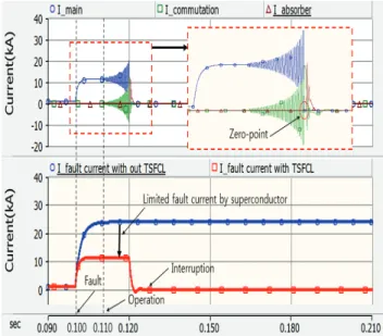
Fig. 5 shows the graph of the fault current limiting and interrupting characteristics of the TSFCL interruption system when a transformer with a 1:1 turns ratio was applied to the TSFCL. Fig. 6 shows the graph of the primary and secondary winding voltages of the TSFCL interruption system with a 1:1 transformer. A 1 kA steady current was conducted before the fault occurrence. When the ground fault was simulated at 0.1 s, the current on the primary side of the transformer sharply increased. At the same time, a counter-electromotive force was generated on the secondary side of the transformer as shown in Fig. 6. As a result, a current exceeding the critical current was conducted to the superconductor. The superconductor was quenched, reducing the current on the secondary side and finally limiting the fault current. The magnitude of the limited fault current was 11.04 kA.
The limited fault current was introduced into the circuit breaker and the circuit breaker opening operation was performed at 0.11 s. At the same time, due to the L and C of the commutation path, a divergent oscillating current was generated at the limited fault current, resulting in a current zero point and fully opening the circuit breaker at 0.1198 s.
The residual current was then discharged to the earth through the arrester. The time when the discharge was completed was 0.129 s. The total interruption time of the TSFCL interruption system with the 1: 1 transformer was 29 ms.
Fig. 4. Simulation circuit diagram of the simulated DC grid.
Fig. 5. Limiting and interrupting characteristic curve of the TSFCL interruption system with a 1:1 transformer.
Fig. 6. Primary and secondary winding voltages of the TSFCL interruption system with a 1:1 transformer.
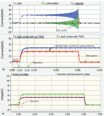
Fig. 7 shows the graph of the limiting and interrupting characteristics of the TSFCL interruption system that used the step-up transformer. Like the 1: 1 transformer, a 1 kA current was conducted in the steady state. When a ground fault occurred at 0.1 s, the superconductor was quenched due to the current induced to the secondary side of the transformer, which limited the fault current on the primary side. The limited fault current was introduced into the mechanical DC circuit breaker and a current zero point was generated at 0.1801 s. The residual current was then discharged to the earth through the arrester and the interruption was completed at 0.1857 s.
Fig. 7. Interrupting characteristic curve of the TSFCL interruption system with a step-up transformer.
Fig. 8. Limiting and interrupting characteristic curve of the TSFCL interruption system with a step-down transformer.
Due to the turns ratio of the step-up transformer, however, the counter-electromotive force on the secondary side was increased and the current conducted to the superconductor was reduced. As a result, the amount of current variation due to the quench of the superconductor was reduced, and the variation of the magnetic flux interlinked with the primary side was decreased. This reduced the burden on the superconductor, but limited the
fault current to a higher magnitude than the 1:1 transformer.
Fig. 8 shows the graph of the limiting and interrupting characteristics of the TSFCL interruption system that used the step-down transformer. A 1 kA steady current was conducted until a ground fault occurred. After the ground fault occurrence, the fault current was limited to 4.7 kA due to the quench of the superconductor connected to the secondary side of the transformer. This is because the current induced to the secondary side was the highest and the changes in the current and magnetic flux generated by the quench of the superconductor were the largest.
The fault current limited by the step-down transformer and the quench of the superconductor was introduced into the mechanical DC circuit breaker and a zero point was generated at 0.1103 s. The interruption was completed at 0.1158 s due to the discharge of the arrester.
3. CONCLUSION
This paper analyzed the fault current limiting and interrupting characteristics using PSCAD/EMTDC-based analysis software by applying step-up and step-down transformers to the TSFCL interruption system. The simulation results show that the TSFCL interruption system operated normally when the step-up and step-down transformers were applied. In addition, as no impedance was generated due to the transformer winding in the steady state, steady current was conducted without any power loss.
When the step-up transformer was applied, the fault current limiting rate decreased but the burden on the superconductor increased. On the other hand, when the step-down transformer was used, the burden on the superconductor increased but the fault current was significantly reduced. Based on the simulation results, the TSFCL interruption system is considered to be an interruption system that can further limit the fault current as well as minimize the burden on the superconductor through the interaction between the transformer and superconductor.
ACKNOWLEDGMENT
This research was supported by Basic Science Research Program through the National Research Foundation of Korea(NRF) funded by the Ministry of Education, Science and Technology (NRF-2015R1D1A1A01059489). In addition, this research was supported by Korea Electric Power corporation [grant number: R16XA01]
REFERENCES
[1] Shreya lyer, W. G. Dunford, and Martin Ordonez, “DC distribution systems for homes,” Power & Energy Society General Meeting, 2015 IEEE, Accession Number: 15538193, Oct. 2015.
[2] Zheng Ganhao, “Study on DC Circuit Breaker,” Intelligent Systems Design and Engineering Applications (ISDEA), 2014 Fifth International Conference on, Accession Number: 14817916, pp.
942-945, Dec. 2014.
[3] H. J. Lee, “Effect of a SFCL on commutation failure in a HVDC system,” IEEE Transactions on Applied Superconductivity, vol. 23, p. 5600104-5600104, 2012.
[4] Feng Zheng, Changhong Deng, Lei Chen, Shichun Li, Yang Liu, and Yuxiang Liao, “Transient Performance Improvement of Microgrid by a Resistive Superconducting Fault Current Limiter,”
IEEE Transactions on Applied Superconductivity, vol. 25, p.5602305, 2015.
[5] B. Pauli, G. Mauthe, E. Ruoss, G. Ecklin, J. Porter, and J.
Vithayathil, “Development of a high current HVDC circuit breaker with fast fault clearing capability,” IEEE Transactions on Power Delivery, vol. 3, pp. 2072-2080, 1988.
[6] P. H. Schavemaker and L. van der Slui, “An improved Mayr-type arc model based on current-zero measurements [circuit breakers],”
IEEE Transactions on Power Delivery, vol. 15, pp. 580-584, 2000.
[7] H. Nakao, Y. Nakagoshi, M. Hatano, T. Koshizuka, S. Nishiwaki, A.
Kobayashi, T. Murao, and S. Yanabu, “DC current interruption in HVDC SF6 gas MRTB by means of self-excited oscillation superimposition,” IEEE Transactions on Power Delivery, vol. 16, pp. 687-693, 2001.