Progress in Superconductivity and Cryogenics
Vol.16, No.3, (2014), pp.10~14 http://dx.doi.org/10.9714/psac.2014.16.3.010
```
1. INTRODUCTION
Steady increase in the volume of demands for power contributes to increased construction of power facilities.
The increased power facilities are designed to have a network system structure to improve power quality through enhanced supply reliability. However, grid connection in this structure reduces total impedance in a power network to make great ground fault current flow when a failure occurs. If the magnitude of the increased ground fault current exceeds the breaking capacity of existing breakers, it may propagate troubles to the breakers and power equipment around the troubled area. Furthermore, there is a greater possibility of secondary accidents like power failures in wide areas[1-5]. As the breaking level of breakers is exceeded to result in reduced power supply reliability and stability, there is an urgent need of tackling the issues. One of the solutions is to replace old breakers by new breakers of great capacities. However, technical constraints and repeated breaker replacement to meet the demand for increasing power are a great economic burden and it is not a fundamental solution[6-8]. Therefore, studies of fault current in relation to reduction have been done, and one method is to study limiters by means of high temperature superconductors. The superconductors feature critical temperature, critical magnetic fields and critical current, and their electric resistance under the critical values is zero. The superconducting fault current limiter uses critical temperature which is one of critical features and supplies power to loads in the system without ohmic loss[8-11]. However, it is necessary to build a cooling
system to keep superconductivity, and a lot of expenses are required to maintain the system. Applying a superconducting limiter to a system to endure ground fault current can reduce the limiter lifespan. Therefore, it is possible to reduce deterioration of superconductors if they limited only ground fault current. This study thus suggested a high speed ground fault current limiter for protecting breakers and power equipment by reducing the ground fault current quickly, concurrently bypassing and limiting the ground fault current to the current limiter. In this study, a simulation system was built to apply a high speed ground fault current limiter to a distribution system. We applied superconducting fault current limiter. It limited the initial fault current. In addition, the time for the back protection operation could obtain due to longer fault duration, when the circuit breaker was not opened. So, We of power capacity and operation characteristics of a superconductor when the system has a failure to ensure the reliability of the power system.
2. DETAILED DESCRIPTION
2.1. Specifications and characteristics of a superconductor used in test
Fig. 1 shows a meander-line superconductor. In this test, a meander-line type thin YBCO film was used, which was deposited on a sapphire substrate. Table 1 shows the specifications of the superconducting thin film. The produced superconductor was 540 mm in length shaped a meander line on a substrate which is 2 inches in diameter and 2mm in width. The critical temperature was 87-88K,
Operation characteristics of a fault current limiter by high speed interrupter and a superconducting element
I. G. Im, I. S. Jung, and H. S. Choi* Chosun University, Gwang-ju, Korea
(Received 18 March 2014; revised or reviewed 24 September 2014; accepted 26 September 2014)
Abstract
Due to continuous increase of electric power consumption, couple of resolutions for improving accuracy in power system like line separation are being studied. The increase of the power demand can cause problems such as supply difficulties of the electricity and broadband outages, failure, etc. When a fault occurs in the power system, a fault current also increases. Fault current creates problems like reduction of lifespan and failure on the power system. In order to resolve these problems, the reduction of initial fault current using the characteristics of superconducting element was applied to fault current limiter. We applied the system to high speed fault current limiter. We found that the superconducting element effectively reduced initial fault current and the fault current was limited by changing operation of high speed interrupter.
Keywords: Interrupter, Superconducting, Fault Current Limiter, Quench
* Corresponding author: [email protected]
I. G. Im, I. S. Jung, and H. S. Choi
Fig. 1. Meander-line superconductor.
Fig. 2. Critical current of a superconductor.
TABLE I
SPECIFICATIONS OF A SUPERCONDUCTOR.
Parameter Value Unit
Diameter 50.8 mm
Width 2 mm
Length 540 mm
The critical
temperature 87-88 K
The critical current
density 3 MA/cm2
Au Thickness 0.1 μm
and the critical current density was 2-3 MA/cm2. Fig. 2 shows the critical current values of the used superconductor.
It was shown that quenching occurred at 19 A and current was gradually increased when 1 V of a voltage source was applied. This was to sharply increase impedance of the superconductor to limit current, and was in charge of reducing the burden on protection facilities and power devices by limiting initial ground fault current when a fault was applied in this test.
2.2. Configuration of high speed interrupter and test of applying superconductor
Fig. 3 shows the structure of a produced high speed interrupter. The high speed interrupter was made by combining a solenoid valve with a vacuum interrupter, and was in charge of bypassing the ground fault current to a line to which the current limiter was connected when the fault occurs on the line. Tables 2 and 3 show the specifications of the solenoid valve and the vacuum interrupter. The
Fig. 3. Structure of high speed interrupter.
TABLEII
SPECIFICATIONS OF A SOLENOID VALVE.
Parameter Value Unit
Input 220 V
Rating stroke 30 mm
Pulling force 15 kg
Weight 4.5 kg
Frequency 60 Hz
Grade of B •
Temperature rise below 75 deg
TABLE III
SPECIFICATIONS OF A VACUUM INTERRUPTER.
Parameter Value Unit
Rated voltage 7.2 kV
Power frequency 20 Hz
Impulse withstand
voltage 60 kV
Rated frequency 60 Hz
Rated current 1250 A
Rated breaking
current 25 kA
Rated closing current 65 kA
Short-circuit current
time 3 sec
solenoid valve was selected in consideration of ideal suction power because it should be able to open contacts when faults happen. The vacuum interrupter shown in Table 3 was the one verified to have an ideal insulation level to be applied to a distribution system. Before testing each type of system failures, a single phase test was performed for which the superconductor was applied to the high speed interrupter. In this test, an analysis was made of limiting characteristics of initial ground fault current depending on application of the superconductor to a normal
11
Operation characteristics of a fault current limiter by high speed interrupter and a superconducting element
line. Fig. 4 shows a circuit for testing the characteristics of ground fault current depending on application of the superconductor. Case 1 is for no application of the superconductor, and Case 2 is for application of the superconductor. Fig. 5 shows characteristics of initial ground fault current where the superconductor was applied.
When the circuits shown in Case 1 and Case 2 of Fig. 4 were made to have an intentional failure, Case 1 showed sharply increasing current values to maximum 266.77 A.
On the other hand, a superconductor was applied in Case 2, it was identified that ground fault current was effectively limited to 29.02 A in a short period of time after having a trouble. The high speed ground fault current limiter is a system for changing and then bypassing a line while quickly limiting ground fault current coming into power facilities when a system has a trouble, in order to limit continuous ground fault current. This test aimed to simulate single, double and triple line-to-ground fault in a system to analyze burden of power and the characteristics of the superconductor for limiting initial ground fault current.
LOAD I
Is I1
I2 Switching Control System
Limiting Unit a contact
b contact CT
Superconductor
LOAD I
Is I1
I2
Switching Control System
Limiting Unit a contact
b contact CT
Case 1
Case 2 Fig. 4. Circuit for testing characteristics of ground fault current depending on application of a superconductor.
(a) Case. 1: Superconductor not applied (b) Case. 2: Application of a superconductor
Fig. 5. Characteristics of initial ground fault current depending on case1 and case 2.
3. Experiments 3.1. Organization and test results
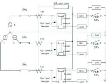
Fig. 6. Test circuit of high speed ground fault current limiter.
Fig. 7. Electrical characteristics in single line-to-ground fault.
Fig. 8. Electrical characteristics in double line-to-ground fault.
12
I. G. Im, I. S. Jung, and H. S. Choi
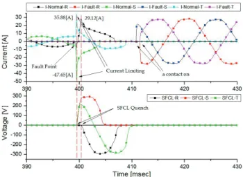
Fig. 9. Electrical characteristics in triple line-to-ground fault.
Fig. 6 shows test circuit for which a high speed ground fault current limiter was applied. In the normal state, current was supplied to the load through b-contact of the high speed interrupter and the superconducting element with no resistance when power voltage of 400 V was applied to each phase through SWR, SWS and SWT. Where single, double and triple line-to-ground faults was generated by using fault switches connected to a load in parallel, the magnitude of the ground fault current increased tens of times in comparison with normal current.
In this case, when the CT sensed ground fault current and the SCR control system applied power to the high speed interrupter, the line was changed to a current limiter. The initial ground fault current coming before the lines changed was limited by a superconductor.
Fig. 7 shows the current limiting characteristics in single line-to-ground fault. When single line-to-ground fault occur through the switch SWR, ground fault current sharply increase and the superconductor quenched if the increased ground fault current exceeds the critical current value of the superconductor. In this case, the magnitude of ground fault current was limited to 29.12 A due to the generated impedance of the superconductor. The burden of power laid on the superconductor was identified 3107.79 W at this time. The operation of the high speed interrupter then contributed to changing lines to limit ground fault current by impedance. The changing time was 16.6 ms.
Fig. 8 shows the current limiting characteristics in double line-to-ground fault. While ground fault current in phase R was limited to 29.12 A, ground fault current in phase S was limited to 47.65 A, when double line-to-ground fault occurred through switch SWR, and fault SWs. This is because the fault was simulated on the basis of 0 degree of phase R. In this case, because the current value of phase S was the greatest value by the phase difference with phase R, ground fault current became greater. However, it was shown that the ground fault current was quickly limited due to the quenched
superconductor, and the burden of power laid on the superconductor was 3270.85 W and 3261.28 W for phases R and S, respectively. The changing time of the high speed interrupter after the fault was 11.59 ms, 11.24 ms.
Fig. 9 shows current limiting characteristics in triple line-to-ground fault. Ground fault current was limited from 29.12 A, 47.65 A, 35.88A for phases R, S and T, respectively, when triple line-to-ground fault occurred through switch SWR, switch SWS, and switch SWT. In this case, burden of power laid on the superconductor for each phase was 3194.44 W, 3428.64 W, and 3180.14 W, respectively. The high speed interrupter changed the line to which the current limiter was connected after 12.17 ms, 11.44 ms, 12.16 ms to limit ground fault current. When the fault occurred. The result of test revealed that ground fault current came into the normal line more than 1 cycle when the superconductor was not applied. Therefore, the superconductor was inserted in a normal line in order to protect protection facilities, for example, a circuit breaker, by effectively limiting initial ground fault current. The ground fault current was limited within a half cycle after a fault occurred. The line change by the high speed interrupter contributed to stably limiting ground fault current by impedance and also to reducing the burden of the superconductor.
4. CONCLUSION
This study aimed to establish a method of quickly limiting initial ground fault current and reducing the burden laid on a superconductor when a system failure occurs in order to address issues, for example, excessive breaking capacity currently caused by increased demands for power.
Although typical superconducting limiters already available are excellent in terms of fault limiting capability, they had issues of burden of power and capacity increase to address continuous ground fault current, and required cooling facilities. Accordingly, this study suggested a method of changing lines to limit initial ground fault current by impedance while a superconductor quickly limits it, and to make an analysis of power burden and operation characteristics laid on the superconductor.
The result of test revealed that 266.77 A of ground fault current came into the normal line more than 16 ms when the superconductor was not applied. But, when applied to the superconductor fault current, Initial fault current was limited to 29.12A, and the line has been change after 12 ms.
It was thought that a high speed interrupter could bypass ground fault current to reduce burden laid on a superconductor. This process can contribute to protecting breakers of which the capacity is excessive when the method is applied to a distribution system, and to tackling failure propagation while addressing the issues of increasing superconductor capacity and reducing cooling facilities.
13
Operation characteristics of a fault current limiter by high speed interrupter and a superconducting element
ACKNOWLEDGMENT
This research was financially supported by the Ministry of Education, Science Technology (MEST) and National Research Foundation of Korea(NRF) through the Human Resource Training Project for Regional Innovation (No. NR F-2013H1B8A2032246).
REFERENCES
[1] B. I. Jung, H. S. Choi, "Combined Effect of the SFCL and Solenoid Coils," IEEE Trans. Appl. Supercond., Vol. 24, pp. 5600404, 2014.
[2] H.W.Choi, H.S.Choi, B.I.Jung, “Operational Characteristics of the High-speed Interrupter for Reliability Enhancement of Power Supply and Demand,” KIEE, Vol. 62, No. 1, pp. 143-148, 연도.
[3] I.G.Im, H.S.Choi, B.I.Jung, I.S.Jeong, H.W.Choi ‘Analysis on Fault Current Limiting Characteristics of Three-phase FCL using high-speed interrupter,” KIIEE, Vol. 2012, No. 10, pp. 214-215, 2012.
[4] I.G.Im, H.S.Choi, B.I.Jung, “Characteristics of a FCL Applying Fast Interrupter According to the Current Limitation Elements,” KIEE, Vol. 61 No. 11, pp. 1752-1757, 2012.
[5] H. S. Choi, B. I. Jung, Y. S. Cho, "Transient Characteristics of a Flux-Coupling Type Superconducting Fault Current Limiter According to Winding Direction," IEEE Trans. Appl. Supercond., Vol. 19, pp. 1827-1830, 2009.
[6] O. B. Hyun, J. W. Sim, H. R. Kim, K. B. Park, S. W. Yim, I. S. Oh,
"Reliability Enhancement of the Fast Switch in a Hybrid Superconducting Fault Current Limiter by Using Power Electronic Switches," IEEE Trans. Appl. Supercond., Vol. 19, No. 3, pp.
1843-1846, 2009.
[7] B. W. Lee, K. B. Park, J. Sim, I. S. Oh, H. G. Lee, H. R. Kim, O. B.
Hyun, “Design and Experiments of Novel Hybrid Type Superconducting Fault Current Limiters," IEEE Trans. Appl.
Supercond., Vol. 18, No. 2, pp. 624-627, 2008.
[8] H. S. Choi, S. H. Lim, "Operating Performance of the Flux-Lock and the Transformer Type Superconducting Fault Current Limiter Using the YBCO Thin Films," IEEE Trans. Appl. Supercond., Vol.
17, pp. 1823-1826, 2007.
[9] Y. S. Cho, H. S. Choi, H. M. Park, "Characteristics of Hybrid-Type SFCL by the Number of Secondary Windings with YBCO Films,"
KIEE Trans. Vol. 55A, pp. 62-66, 2006.
[10] M. Noe, K. P. Juengst, F. N. Werfel, S. Elschner, J. Bock, F. Breuer, R. Kreutz, “Testing bulk HTS modules for resistive superconducting fault current limiters,” IEEE Trans. Appl.
Supercond., Vol. 13, pp. 1976-1979, 2003.
[11] H. S. Choi, O. B. Hyun, H. R. Kim, K. B. Park, "Switching properties of hybrid type superconducting fault current limiter using YBCO stripes," IEEE Trans. Appl. Supercond., Vol. 12, pp.
1833-1838, 2002.
14