Vol. 18, No. 6, pp. 166-173, December 2014
Mechanical Behaviors of CFRP Laminate Composites Reinforced with Aluminum Oxide Powder
Oh-Heon Kwon*, Yu-Seong Yun**†and Yeong-Rok Ryu***
(Received 29 October 2014, Revised 02 December 2014, Accepted 03 December 2014)
Abstract: In this study, a laminated composite material with dispersing aluminum oxide powder between the CFRP laminate plies, and also CFRP composites without aluminium oxide powder were fabricated for Mode Ⅰ experiments using the DCB specimen and a tensile test. The behavior of the crack and the change of the interfacial fracture toughness were evaluated. Also in order to evaluate the damage mechanism for the crack extension, the AE sensor on the surface of the DCB test specimen was attached. AE amplitude was estimated for CFRP-alumina and CFRP composite. And the fracture toughness was evaluated by the stress intensity factor and energy release rate. The results showed that an unstable crack was propagated rapidly in CFRP composite specimen along with the interface, but crack propagation in CFRP-alumina specimen was relatively stable. From results, we show that aluminium oxide powder spreaded uniformly in the interface of the CFRP laminate carried out the role for preventing the sudden crack growth.
Key Words:Carbon Fiber Reinforced Plastic, Laminates, Aluminum Oxide Powder, Fracture Toughness, Acoustic Emission
**
†
Yu-Seong Yun (corresponding author) : IBS Innovation Co. E-mail : [email protected], Tel : 051-629-6469*Oh-Heon Kwon : Department of Safety Engineering, Pukyong National University.
***Yeong-Rok Ryu : Department of Safety Engineering, Graduate School, Pukyong National University
1. Introduction
The fiber reinforced plastic(CFRP) materials have been developed as the advanced composite materials in the several industrial fields as like mechanics, electricity, structure and others during a few decade. Especially CFRP composites have been applying to the aerospace and vehicle for the lightweight design owing to the high specific strength and modulus
1). However, CFRP composites
must be fabricated by the laminating method for
the useful thickness. Therefore, the delamination
situation happens often in the interface of the
laminated plies and it can induce
2)the sudden
crack extension and fracture of the structures. Thus,
the improvement of the fracture toughness of the
interface between the laminate plies becomes an
important key role to obtain the safety and healthy
condition of the CFRP composite structures. Many
researchers
3~5)have studied by the several methods
for the interlaminar fracture of the CFRP laminate
composites. However until now the researches for
the CFRP composite with the interlayer spreaded
the reinforced powders between the laminates have
not been done sufficiently. In this study, the
CFRP-alumina composite spreaded with aluminum
oxide powder in the interface between laminates
was evaluated for the fracture toughness. And the evaluation for restraint properties of the crack extension under the DCB(Double cantilever bending) test
6)and also AE characteristics experiment were implemented to estimate the crack behaviors. The experiments were performed by using the two kinds of specimens of the only CFRP prepreg laminate and CFRP laminates spreaded and reinforced by aluminum oxide powders in the interface. Also the tests were implemented with AE sensors under the tension loading and DCB condition for the mechanical properties and interlaminar fracture toughness evaluation.
2. Experimental materials and method
2.1 Materials
The CFRP material was a woven type carbon fiber reinforced prepreg(Hankuk Cabron Co.) and an aluminum oxide powder has particle size of 1
(R&B Inc.). The CFRP prepreg was cut to a size of 250mm×250mm square and laminated with 12 plies.
One type is laminated with only CFRP prepreg and another type is laminated by CFRP prepregs with an aluminum oxide layer between sixth and seventh ply. The powder mixed in a ratio of 1:5 with an ethanol was sprayed evenly over the prepreg to make the uniform aluminum oxide layer. From now, the specimen laminated with only CFRP prepregs
Table 1 Composition of the fiber and resin in CFRP prepreg
Material(CF 3327EPC) Value
Fiber Wt. (gr/m
2) 205
Resin Wt.(gr/m
2) 148
Total Wt.(gr/m
2) 353
Thickness, t (mm) 0.27
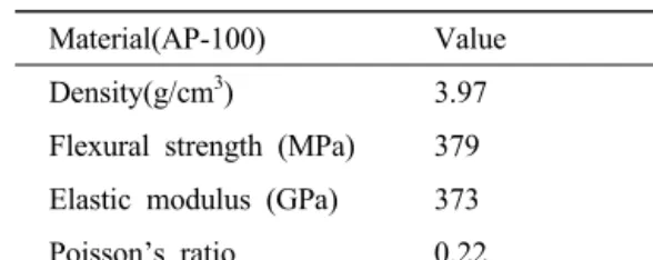
Table 2 Engineering properties of aluminum oxide powder
Material(AP-100) Value Density(g/cm
3) 3.97 Flexural strength (MPa) 379 Elastic modulus (GPa) 373 Poisson’s ratio 0.22
is called as C type specimen and the CFRP laminate reinforced by the aluminum oxide powder is called as CA type specimen. Table 1 shows composition of the resin and carbon fiber of the CFRP prepreg and Table 2 shows the engineering properties of the aluminum oxide powder used in the experiment. The composite laminates were formed at 130℃ temperature during 1 hour in the hot press for a hardening. The final thickness was about 3.10mm for CFRP laminates and was obtained about 3.25mm in CFRP laminates reinforced by aluminum oxide powder. The hardened composite laminate was machined as the tensile and DCB test specimen according to the ASTM D3039
7)and D5528
8), respectively.
Fig. 1 shows the figuration and dimension of the (a)tensile and (b)DCB test specimen. A thin aluminum tab is attached on the both ends of the tensile specimen by using an araldite epoxy resin with a hardner to prevent a damage and slip from the fixture of the machine. The bonding surfaces are scratched with an emery paper of #100 and cleaned by acetone solvent. And the tab has been taped with angle of 30˚ to prevent a stress concentration. On the other hand, the square aluminum blocks were attached on the end of DCB specimen and treated in the same method as the tensile specimen. The fabricated tensile and DCB specimens with tabs or blocks were cured in the electric furnace at 100℃
during 30min. The precrack was formed by inserting
a thin cooking foil on the DCB specimen and the
final crack length of was formed by inserting a fatigue crack as 2~3mm under a dynamic universal test machine.
2 14
20
Tab Tab
Aluminum Tab
30°
140
Unit : mm 20
(a) Tensile test specimen
12
Unit : mm
24 24
30 5
a
020
∅ 10 12
L : 110 122
CFRP
Al
2O
3Foil
P P
25
(b) DCB test specimen Fig.1 Configuration of specimens
2.2 Experimental methods
A tensile test was carried out by the displacement control (1mm/min) by using a universal test machine(50kN), and the strain in the center of the specimen was obtained by attaching a strain gauge.
The DCB fracture test was performed by the mini tensile tester(Tinus Olsen Inc., 5kN) with 0.5mm/min displacement control. A crack extension length was measured by using a stereoscopic- microscope and recorded through a digital converter.
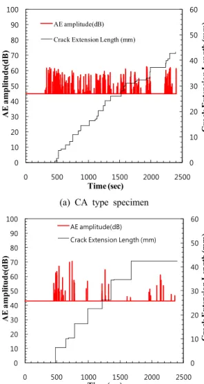
AE system with a built-AEDSP32 board was used for AE characteristics measurement about damage assessment under fracture tests. The AE sensor R15
of resonant frequency 150kHz ,which has a band-pass filter of from 100kHz to 300kHz, was used. And a silicone as a contact medium was placed between the specimen and the sensor and the AE sensor was pressed by the cloth tape in order to improve the transfer efficiency of the AE signals.
3. Results and discussion
3.1 A mechanical behavior for a tensile test
Fig. 2 shows stress-strain relationship curves by a tensile test for two types of specimen, which one is made up with only CFRP composite(C type) and another is CFRP composite with aluminum oxide powders (CA type).
0 0.02 0.04 0.06 0.08 0.1 0.12
0 0.0005 0.001 0.0015 0.002 0.0025
St ress (G Pa )
Strain
CA type C type
Fig. 2 Stress-strain curves for CFRP composite (C type) and CFRP-alumina composite (CA type) under tensile test
Table 3 Mechanical properties of specimens
Specimen Elastic Modulus, E (GPa)
Poisson’s ratio, ν
C type 54.12 0.05
CA type 53.01 0.07
The results in two types of the specimen are almost the same. The obtained mechanical properties are shown in the Table 3.
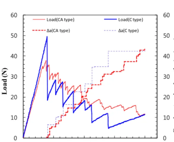
3.2 Interlaminar fracture under DCB test Fig. 3 shows the relationships between the load and displacement and crack extension length under mode I test using DCB specimen for two kinds of specimen. The load in each type specimen was increased linearly until the maximum load point.
The maximum load was about 49N and 37.5N for the C type specimen and CA type specimen, respectively, even though the pop-in was occurred in CA type specimen. The crack initiated directly after the sudden load drop as the crack length becomes 6.45mm and 0.42mm, respectively. After first initiating, the crack extension and load drop were intermittent at both types of specimen and the last crack extension length was 42.41mm and 43.23mm at the same displacement of 20mm, respectively.
The load reduction average is about 2.575N, which changes from 0.35N to about 7.3N and the change in the displacement was obtained as the average of about 0.5mm to a minimum of about 0.03mm up to about 2.01mm in the case of CA type specimen. In
0 10 20 30 40 50 60
0 10 20 30 40 50 60
0 5 10 15 20
C ra ck e xt ens io n l engt h , Δ a ( mm)
Lo ad (N )
Displacement (mm)
Load(CA type) Load(C type)
Δa(CA type) Δa(C type)
Fig. 3 Load-displacements and crack extension length variation of DCB fracture test
the case of C type specimen, load was reduced an average of about 11.65N, and an average change of the displacement showed 1.77mm. From the results, load reduction ratio in CA type specimen which the aluminum oxide powder is spreaded was stable more 75% than that of C type specimen. It is expected to act as a stabilizer to inhibit a sudden crack growth by the thin aluminum oxide powder layer in the interface of CFRP laminate composite. Fig. 4 is a typical model of observing the shape of the crack growth in CA type.
(a) Type I-1 (b) Type I-2
(c) Type I-3 (d) Type I-4
Fig. 4 Schematic four models of crack growth acquired from a fracture test(CA type specimen)
They show that (a)Type I-1 indicates the growth of cracks along the interface between the laminated CFRP layers and aluminum oxide powder, (b)Type I-2 indicates the growth of cracks in the inner of aluminum oxide powder, (c)Type I-3 shows the growth of cracks along the other side of the interface again across the aluminum oxide powder layer while growth of cracks along the interface of CFRP laminate with aluminum oxide powder layer.
(d)Type I-4 shows the form of a growing crack in
both interface based on the aluminum oxide powder
layer. Fig. 5 is a typical model corresponding to the
progress observed crack growth shape in the C type
specimen. Fig. 5(a) shows the growth of cracks
along the carbon fiber direction of 0˚, and (b)
indicates the crack growth in accordance with the
interface of the laminate. Fig. 5(c) shows that the crack growth along the 0° weft fiber layer interface advances through the interlayer, (d) represents the crack combined with each other to grow into 0°
fiber orientation. The most typical crack growth model is Fig. 4(a) and (c) in the case of CA type specimen and Fig. 5(b) in the case of C type specimen expects the sudden load drop and crack growth.
(a) Type II-1 (b) Type II-2
(c) Type II-3 (d) Type II-4 Fig. 5 Schematic four models of crack growth
acquired from a fracture test(C type specimen)
3.3 Interlaminar fracture resistance evaluation under DCB test
Fig. 6 shows the relationships between the crack extension length(Δa) and stress intensity factor K
I. The fracture toughness for a mode I fracture test can be found by the following equation (1)
9).
․
(1)
Here P, B, W and are load, thickness, width and crack length, respectively.
The mode I fracture toughness K
ICwas estimated as about 2.91 MPa·m
1/2and 4.41 MPa·m
1/2in CA type and C type specimen, respectively. While the fracture resistance of the CA type specimen tends to decrease progressively, fracture resistance in C type specimen tends to be lowered suddenly as a crack
grows rapidly. A stress intensity factor fracture toughness K
ICin the C type specimen is higher than K
ICof CA type specimen. However the fracture resistance value of CA type specimen is higher than that of C type specimen after the crack advanced.
0 1 2 3 4 5 6
0 10 20 30 40 50
St re ss in te ns ity fa ct or , K
Ⅰ(M Pa m
1/2)
Crack extension length, Δa (mm)
CA type C type
Fig. 6 The interlaminar fracture toughness resistance by the stress intensity factor K
Furthermore modeⅠ energy release rate G under DCB test was obtained by using MBT (Modified Beam Theory) formula (2) on the basis of the ASTM D 5528-01
8).
(2)
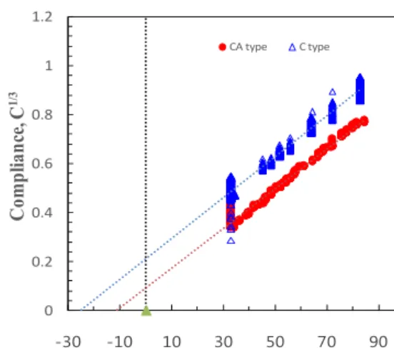
Here, P, , B, and Δ are the load, load point displacement, thickness, crack extension length and correction factor. The correction factor is found by the relationship between a compliance C of the equation (3) and a crack extension length.
(3)
The correction factor Δ is obtained from the size
of the slope-intercept axis passing crack length axis.
Size of Δ is to complement the deviation of the crack extension length because that a crack tip area is not completely fixed.
0 0.2 0.4 0.6 0.8 1 1.2
-30 -10 10 30 50 70 90
Co mp lia nc e, C
1/3Crack length, a (mm)
CA type C type
Fig. 7 The correction factor from the relationship between compliance and crack length
Fig. 7 shows the correction factor Δ obtained from the relationship between compliance and crack length. In the case of CA type specimen, Δ was –6.674mm, and about –24.13mm for C type specimen. Using the correction factor, the energy release rate by the equation (2) is shown in Fig. 8.
0 0.5 1 1.5 2 2.5 3
0 10 20 30 40 50
G ( K J /m
2)
Crack extension length, Δa (mm)
CA type C type