pISSN 1229-3008 eISSN 2287-6251
Progress in Superconductivity and Cryogenics
Vol.17, No.1, (2015), pp.36~39 http://dx.doi.org/10.9714/psac.2015.17.1.036
```
1. INTRODUCTION
Recent rapid Increase in Use if and range of portable electronic devices, the use of cables for their charging is becoming more and more inconvenient. IT devices especially require frequent charging or additional portable batteries. Accordingly, WPT was again attention as a way of solving this problem. The existing WPT technology was divided into the magnetic induction type and the microwave type. The magnetic induction type used the principle of electromagnetic induction. It had a 90% higher power transmission efficiency. So, magnetic induction was most widely used in daily life in electrical toothbrushes, wireless razors, cellular phone charging pads, etc. However, it had a very short transmission distance. In addition, a slight mismatch of the coil angles significantly reduced the efficiency. The microwave type had long transfer distances and very high efficiency. However, it affected the human body because it used the GHz-band. Its efficiency also varies according to the weather or topographical effects[2-5]. To solve these problems, the magnetic resonance type was proposed. Announced by the MIT research team of Marin Soljacic in 2007, the magnetic resonance type switched on a 60W light bulb at a distance of 2 m and had an approximately 40% efficiency. Also, it used a non-radiation magnetic field, it was not significantly affected by the human body, the weather, and the topographical. The magnetic resonance system consists of four coils: resonance coils (a transmitter and a receiver), a
source and a load coil. When the transmitter (Tx) and the receiver (Rx) had the same resonance frequency, the evanescent wave coupling between the transmitter and receiver coils was used in this system. The efficiency and distance of power transmission depend on the characteristics of the resonance coil. Until now, the WPT mainly used copper or enamel, which satisfied the needs for convenience and economic feasibility. However, because the normal conductor coil had a some resistance and its impedance increased within a high frequency range, there was a limit in improving the Q-factor[6-7].
In this paper, the superconductor coil was used as the resonance coil to improve the efficiency of magnetic resonance WPT. The superconductor had a high flux density than in the normal conductor. Therefore, the superconductor coil could have a high Q-factor. In addition, its current density was 100 times higher than that of copper, and enabled high-capacity power transmission.
2. MAIN PARAMETERS 2.1. WPT diagram
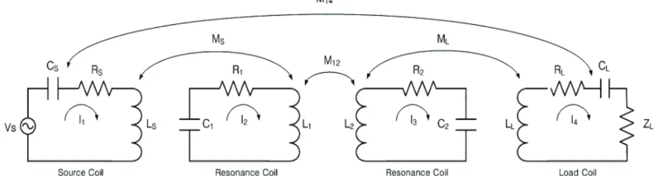
Fig. 1 shows the diagram of the magnetic resonance WPT system. The magnetic resonance WPT system had a source coil, a load coil, and resonance coils (Tx and Rx).
The four coils had self-resistance (R), self-inductance (L), and self-capacitance (C). Each coil had a closed loop.
Vs=I1Z1−I2⋅ jωMs (1)
Characteristic of wireless power transmission S-Parameter for a superconductor coil
In-Sung Jeong, Byung-Ik Jung, and Hyo-Sang Choi* Chosun University, Gwangju, Korea
(Received 4 March 2015; revised or reviewed 18 March 2015; accepted 19 March 2015)
Abstract
Many studies are being conducted to implement wireless charging, for example, for cellular phones or electronic tooth brushes, via wireless power transmission technique. However, the magnetic induction method had a very short transmission distance. To solve this problem, the team of Professor Marin Soljacic proposed a magnetic resonance system that used two resonance coils with the same resonance frequency. It had an approximately 40% efficiency at a 2m distance. The system improved the low efficiency and short distance problems of the existing systems. So it could also widen the application range of wireless power transmission.
Many studies on the subject are underway. In this paper, the superconductor coil was used to improve the efficiency of magnetic resonance wireless power transmission. The resonance wireless power transmission system had a source coil, a load coil, and resonance coils (a transmitter and a receiver). The efficiency and distance depended on the characteristics of the transmitter and receiver coils that had the same resonance frequency. Therefore, two resonance coils were fabricated by superconductors. The current density of the superconductor was higher than that of the normal conductor coil. Accordingly, it had a high quality-factor and improved efficiency
Keywords: Superconductor coil, Resonance, Wireless power transmission, Quality-factor
* Corresponding author: [email protected]
In-Sung Jeong, Byung-Ik Jung, and Hyo-Sang Choi
Fig. 1. Resonance WPT diagram.
0=I2Z2−I1⋅ jωMS −I3⋅ jωM12 (2) 0=I3Z3−I2⋅ jωM12−I4⋅ jωML (3) 0=I4Z4−I3⋅jωML (4)
Using a system of equations, the voltage and current relationship in each closed loop could be determined[8].
In (1), jωMs was the mutual inductance between the source coil and the transmitter coil. The source coil and the transmitter coil transmit power using electromagnetic induction. Then the transmitter coil transmits power via evanescent wave coupling with the receiver coil. At that time, the following equation was obtained using the coupled mode theory between the transmitter and the receiver[9].
2 12 1 1
1 (i 1 )a i a
dt
da =− ω +Γ + κ (5)
1 21 2 2
2 (i 2 )a i a
dt
da =− ω +Γ + κ (6)
In (5) and (6), a1 and a2 were the magnitudes of evanescent wave coupling, ω1 and ω2 were the resonance frequencies, Γ1 and Γ2 were the evanescent coefficients of the resonance coils, and κ was the coupling coefficient. When the coupling appears, the coupling coefficient shifts the resonance frequency. That was, a larger coupling coefficient makes two resonance frequencies, whereas a smaller coupling coefficient makes a single resonance frequency.
) cos(
) 0 ( )
( 1
1 t a e e t
a = −iwt −Γt κ (7) )
sin(
) 0 ( )
( 1
2 t ia e e t
a = −iwt −Γt κ (8)
Γ +Γ
+
Γ
Γ
Γ +Γ
Γ Γ Γ Γ
= 2
2 2
1 1
R L R
S R L
R S R L
κ κ
η (9)
Equations (7) and (8) were obtained by solving in (5) and (6) under the assumption that the two resonance coils had the same frequency. Each evanescent wave coupling
appears in either cos wave and sin wave, the frequency must be maximum and minimum. Equation (9) showed the power transmission efficiency. In this equation, S was the source coil, L was the load coil, and R was the resonance coil. The coupling coefficient and the evanescent coefficient of the coils affected the efficiency.
2.2. Quality-factor
The energy stored in the coil disappears over time due to the resistance in the coil itself. The degree of loss is the Q-factor, and shown in (10) [5].
R factor fL
Quality− =2π (10)
The Q-factor could be improved by reducing the resistance of the coil. But the normal conductor coil had resistance regardless of the temperature. On the contrary, the superconductor coil could have a high Q-factor because its had low resistance at the critical temperature.
2.3. Coil Design
Fig. 2 shows the helical-type coil parameter. D was the coil height, W was the coil thickness, S was the distance between the coils, and H was the coil length.[9]
H Dn nH D
L = +
45 . ) 0
( 2 2 (11)
( )( )
− −
=
−
ds w n
pF D
C 11.45cosh r 1 )
(
1
ε (12)
The inductance(L) and the capacitance(C) could be calculated by using equations (11) and (12), wherein n was the number of coil turns. The superconductor coil is a tape type, as shown in Fig. 3 (a). For the comparative test, the same tape-type copper coils were fabricated as shown in Fig. 3 (b). Table. 1 shows the parameters of the resonance coils. The resistance values of the superconductor coil and the normal conductor coil were 0.1 Ω and 0.4 Ω, respectively. The superconductor coil required a lead wire to connect it to the outside because it used a cooling system. The connection of the lead wire produced resistance. Equations (11) and (12) were used to determine 37
Characteristic of wireless power transmission S-Parameter for a superconductor coil
Fig. 2. Helical coil parameter.
(a)
(b)
Fig. 3. (a) Superconductor (b) Normal conductor.
TABLEI
Q-FACTOR OF A SUPERCONDUCTOR COIL AND A NORMAL CONDUCTOR COIL.
Superconductivity Normal Conductivity
Resistance (Ω) 0.1 0.4
Inductance (μH) 22.3 12
Capacitor (pF) 7.93 14.7
Q-factor 1.6e4 2.2e3
the inductance and capacitance of the resonance coil.
Equation (10) was used to determine the Q-factor.
3. EXPERIMENT 3.1. Experiment composition
Fig. 4 shows the real test process. The source and load coils were wound around a 20cm diameter cylinder in a single loop. The resonance coil was wound in helical-type around a 30cm diameter cylinder. Copper, which was most frequently used for WPT, was used for the normal conductor coil in the comparative test with the superconductor coil. The resonance frequency was 12 MHz, and a network analyzer was used to measure the S-parameter. The voltage and current of the Tx and Rx were measured to calculate the efficiency. Fig. 5 shows cooling system. It maintain the critical temperature for the superconductor coil. The cooling system was fabricated using polystyrene to produce no effect on the WPT. The superconductor was the high-temperature superconductor, and liquid nitrogen was used to maintain the critical temperature..
Fig. 4. Experiment composition.
Fig. 5. Cooling system for the maintenance of superconductivity.
3.2. Experiment analysis
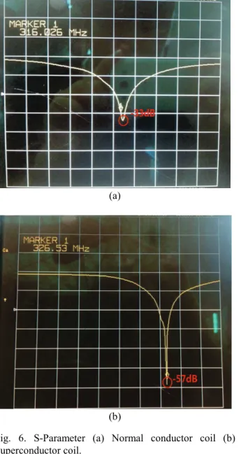
Fig. 6 shows graphs of S11 measured by the network analyzer. S11 of the S-Parameter is the reflection coefficient. The transmitter sent a signal and measured amount that signal was back. The efficiency of the antenna was high when the reflection coefficient was low. The X and Y coordinates refer to the frequency and the dB, respectively. Y coordinate indicated one interval to 10 dB.
The measurements were performed with a 75cm distance between the resonance coils without frequency separation and that had the highest efficiency, according to Equations (5)-(8). Fig. 6 (a) shows the S-parameter when the normal conductor coil was used. it was reflected approximately -7.9 dB. Fig. 6 (b) shows the S-parameter with the superconductor coil. The reflection-coefficient was approximately -14.3 dB. The reflection-coefficient was approximately -6.4 dB lower in the superconductor coil than in the normal conductor coil.
Fig. 7 shows graphs of the efficiency. The efficiency was measured at the 75cm distance between the resonance coils, which had the best resonance characteristic. At that 38
In-Sung Jeong, Byung-Ik Jung, and Hyo-Sang Choi
(a)
(b)
Fig. 6. S-Parameter (a) Normal conductor coil (b) Superconductor coil.
Fig. 7. Resonance WPT efficiency (a) Normal conductor coil, (b) Superconductor coil.
time, the approximate efficiency levels of the normal conductor coil and the superconductor coil were
approximately 32% and 41%, respectively. At the distances other than 75 cm, the superconductor coils also had higher transmission efficiency.
4. CONCLUSION
In this paper, a high-efficiency WPT system was implemented using the low-resistance characteristic of the high-temperature superconductor. The superconductor coil was wound in helical-type around a 30cm-diameter cylinder, and it was applied only to the resonance coils. In the comparative test which copper was most widely used for WPT, was fabricated with the same shape as the superconductor. Its efficiency improved by approximately 9% at a distance of 75 cm. The reflection-coefficient for the Tx and the Rx was measured using a network analyzer, and it was approximately -24 dB lower in the superconductor coils than in the normal conductor coils.
The frequency selectivity characteristic was also higher in the superconductor coils.
ACKNOWLEDGMENT
This research was financially supported by the Ministry of Education, Science Technology (MEST) and National Research Foundation of Korea (NRF) through the Human Resource Training Project for Regional Innovation (No.
NRF-2013H1B8A2032246)
REFERENCES
[1] Nikola Tesla, "Apparatus for transmitting electrical energy", U.S.patent 1119732, 1914.
[2] M.R.Lee, S.U.Kang, Y.H.Kim, S.H.Cheon, T.H.Jung, "wireless transfer", KIEE, vol.59, No.1, 2010.
[3] S.H.Cheon, Y.H.Kim, M.L.L, S.Y.Kang, "Circuit Model Based Analysis of a Wireless Energy Transfer System via Coupled Magnetic Resonances", IEEK, Vol.16, No.04, 2011.
[4] S.H.Lee, H.M.K, H.J.Kim, S.W.Kim, "Wireless Power Transmission using Electromagnetic Inductive Coupling and LC Resonant", KIEE, Vol.62, No.3, pp. 349-354, 2013.
[5] I.S.Jeong, H.S.Choi, "Characteristics of Wireless Power Transmission applying the Superconducting coil", KIEE, Vol.62, No.6, pp. 762-766, 2013.
[6] Andre Kurs, Aristlidis Karalis, J. D. Joannopoulos and Marin Soljacic, "Wireless power transfer via strongly coupled magnetic resonances", Science, pp. 83-86, Jul. 2007.
[7] Aristlidis Karalis, J. D. Joannopoulos and Marin Soljacic,
"Efficient wirless non-radiative mid-range energy transfer", annals of Physics 323, pp. 34-38, 2008.
[8] J.Y.Jang, J.Hur,Y.N.Kim, "Novel Mutual Inductance Formula for the Magnetic Resonance Wireless Power Transmission System Using Helical Coils", KIEES, Vol.23, No.6, pp. 669-681, 2012.
[9] J.W.Kim, H.H.Ji, Y.G.Choi, Y.H.Yun, K.H.Kim, Y.J.Park, "Study on Arrangement of Self-Resonant Coils in Wireless Power Transfer System Based on Magnetic Resonance", KIEES. Vol.21, No.6, pp. 564-572, 2010.
39