Interest in the combination of information technology (IT) and energy technologies had increased. Based on such combination, RFID, wireless charging, AMI, and smart grid products have been developed. Wireless power transmission (WPT) is the transfer of energy without a wire in the free space that is used as a medium. This method has the advantages of convenient power supply, real-time power control, and free-from-space restriction. Upon realization of this technology, a paradigm shift may be initiated in the IT market [1, 2]. The WPT technology included methods that use microwaves, magnetic induction, and magnetic resonance. In the microwave method, electric power is transferred using a high-frequency band of GHz.
The USA’s NASA is developing high-capacity energy transmission technologies that uses microwaves for the space-based solar power project. However, the wireless system requires a high output voltage, and energy is radiated due to the high frequency that affects human body.
Magnetic induction is a wireless charging method through inductive coupling, which is used for electric toothbrushes and smart phones. However, its transmission efficiency could be enhanced only when the distance between the transmitter and receiver coils became very short. The
efficiency of magnetic induction decreased abruptly in the same location, due to its directional nature to the magnetic field. Prof. Marin Soljacic of MIT suggested the magnetic resonance method in 2007. In this method, energy was transferred by the combination of damped waves through the frequency resonance between the transmitter and receiver coils. Moreover, power could be transferred regardless of the location of the charging equipment. Due to these advantages, the magnetic resonance method is being widely studied in research institutes and companies.
To enhance the transmission efficiency of the magnetic resonance type, a high Quality-factor (Q-factor) might be maintained. However, the Q-factor was affected by the impedance change according to the conditions of the surrounding conductors and systems. Therefore, solutions for improving the Q-factor value were required [3-6]. To enhance the transmission efficiency of the magnetic resonance method through Q-factor improvements, superconductor coils were applied to this study. The transmission efficiency of the superconductor coil was confirmed to be better than that of the normal conductor coil [7]. The superconductor coil might be cooled below the critical temperature. Accordingly, the use of cooling system to cool the superconductor coil was inevitable. In comparison, the WPT system was affected by electromagnetic interferences and surrounding conductors that formed an electromagnetic shield. To secure the
Analysis of transmission efficiency of the superconducting resonance coil according the materials of cooling system
Yu-Kyeong Lee, Jun-Won Hwang, and Hyo-Sang Choi*
Chosun University, Gwangju, Korea
(Received 19 February 2016; revised or reviewed 24 March 2016; accepted 25 March 2016)
Abstract
The wireless power transfer (WPT) system using a magnetic resonance was based on magnetic resonance coupling of the transmission and the receiver coils. In these system, it is important to maintain a high quality-factor (Q-factor) to increase the transmission efficiency of WPT system. Our research team used a superconducting coil to increase the Q-factor of the magnetic resonance coil in WPT system. When the superconductor is applied in these system, we confirmed that transmission efficiency of WPT system was higher than normal conductor coil through a preceding study. The efficiency of the transmission and the receiver coil is affected by the magnetic shielding effect of materials around the coils. The magnetic shielding effect is dependent on the type, thickness, frequency, distance, shape of materials. Therefore, it is necessary to study the WPT system on the basis of these conditions. In this paper, the magnetic shield properties of the cooling system were analyzed using the High-Frequency Structure Simulation (HFSS, Ansys) program. We have used the shielding materials such as plastic, aluminum and iron, etc. As a result, when we applied the fiber reinforced polymer (FRP), the transmission efficiency of WPT was not affected because electromagnetic waves went through the FRP. On the other hand, in case of a iron and aluminum, transmission efficiency was decreased because of their electromagnetic shielding effect. Based on these results, the research to improve the transmission efficiency and reliability of WPT system is continuously necessary.
Keywords: Superconductor coil, Wireless power transfer, Quality-factor, Shielding effectiveness, Cooling system
practicality of the superconductor resonance coil, studies on shield effectiveness were required. In this study, shielding materials such as bakelite, fiber reinforced polymer (FRP), plastic (PVC), aluminum, and Iron were used for the cooling system through the high-frequency structure simulation (HFSS, Ansys Ltd). The shield effectiveness of these materials were analyzed.
2. THOERY 2.1. Resonance and the Q-factor
Resonance was an electric oscillation that occurred upon the coincidence between the external power frequency and the resonance frequency of the resonance circuit. For magnetic resonance WPT, not only external power but also resonance circuits were required. The resonance circuit designed using the R, L, and C passive elements was simple but the most important resonator for WPT. The exchange between the magnetic energy accumulated in the inductor (L) and the electric energy accumulated in the capacitor (C) results in a resonant frequency generated by the resonance between the coils.
The resonance frequency of the resonance circuit could be variously produced with different L and C element values, as shown in equation (1) [7].
LCf 2
1 (1)
Using Equation (1), the resonator could perform WPT at a specific frequency and have a frequency-selective Q.
When a frequency was selected, a bandwidth or the Q-factor was determined, as shown in equation (2) [7].
CLfactorR
Q 1 (2)
The high Q-factor value meant the less energy loss than the energy accumulated in the circuit, and the higher efficiency. In typical WPT, antennas were prepared using normal conductor coils. However, there were limitations in the enhancement of the Q-factor due to the resistance from the normal conductor coil itself. In this study, to overcome such limitations, a superconductor coil with a very low resistance was suggested. Table 1 presents the Q-factor values obtained using Equation (2).Superconductor coil had higher Q-factor value than that of normal conductor coil. So, we chose superconductor will as receiver and transmitter parts because the superconductor coil was expected to overcome the limitation of the Q-factor in magnetic resonance WPT.
2.2. Electromagnetic shielding theory
Electromagnetic shielding effectiveness (SE) is the electromagnetic strength that increases or decreases according to shielding materials. When a magnetic wave is directed to a shielding material, the wave is reflected on the surface or penetrates it. And then repetitive multiple
reflection, destructive interference, or penetration occurs inside. The reflection signal is generated in the direction of the incident wave, and the penetration signal is generated behind the shielding material. The electromagnetic shielding performance means the ratio between the incidence energy of a wave in a specific space and the penetration energy. Eq. (3) represents the shielding performance as a sum of the absorption loss (A), reflection loss (R), and internal reflection loss (M) [8-10].
Shielding Effectiveness (SE) = A + R + M (3)
3. SIMULATION DESIGN
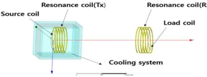
Fig. 1 shows the superconductor coils for WPT system.
A cooling system for the superconductor coils were prepared to analyze the shielding effectiveness through HFSS simulation. bakelite, Fiber Reinforced Polymer (FRP), plastic(PVC), aluminum, and iron were the most common superconductor cooling system. It was horizontal 850mm, vertical 850mm, a height of 750mm, thickness 100mm. Table Ⅰ shows the Superconductor coil design.
Source coil and Load coil was a copper. Resonance (Tx, Rx) coil was a superconductor. The distance was 2m between the transmitter and receiver coils. Table Ⅱ shows the specifications of the cooling system using the materials.
The 1W external power was applied. The superconductor coil was used only in the transmitter to minimize the size of the superconducting wireless power transmission (WPT) system and to secure the freedom of the receiver.
Fig. 1. Cooling system for superconductor coil.
TABLE Ⅰ
S UPERDCONDUCTOR COIL DESIGN .
TABLE Ⅱ S PECIFICATIONS OF MATERIALS .
FRP Bakelite PVC Aluminum Iron Relative
permittivity 4.4 4.8 2.7 1 1
Relative
permeability 1 1 1 1.00021 4000
Source coil
Resonanc e coil(Tx)
Resonance coil(Rx)
Load coil
Turn 1 5.5 5.5 1
Diameter (mm) 250 325 325 250
Thickness (mm) 10 10 10 10
Pitch 0 5 5 0
47
(3)
Analysis of transmission efficiency of the superconducting resonance coil according the materials of cooling system
4. SIMULATION RESULTS ANALYSIS 4.1 S-parameter measurement result
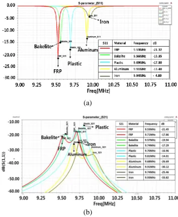
Reflection coefficient (S 11 ) was a reflection degree of the input. When high reflection coefficient (S 11 ) represents a low transmission efficiency. Transmission coefficient (S 21 ) is the degree to which the electromagnetic wave is transmitted through a certain medium. The high reflection coefficient (S 21 ) has high transmission efficiency.
Fig. 2(a) represents the reflection coefficient (S 11 ) when the cooling vessel was made using FRP, bakelite, PVC, aluminum, and iron. When FRP was used, the resonance frequency was 9.53MHz, and the reflection coefficient S11 was about -21dB. When bakelite was used, the resonance frequency was 9.56MHz, and the reflection coefficient was -15dB. When PVC was used, the reflection coefficient was about -17dB and the resonance frequency was 9.69MHz.
When aluminum and iron were used, the resonance frequency and the reflection coefficient were -13dB at 9.1MHz and -4dB at 9.4MHz respectively.
Fig. 2(b) represents the transmission coefficient S 21 according to the cooling vessel materials. The same materials as in Fig. 2(a) were used for the cooling vessel.
FRP had the transmission coefficient -17dB at the resonance frequency 9.71MHz. Bakelite had the transmission coefficient -17dB and the resonance frequency 9.74MHz. PVC had the resonance frequency 9.81MHz and the reflection coefficient S 21 was about -14dB. Aluminum and iron had the resonance frequencies 9.68MHz and 9.74MHz respectively. And the reflection coefficient S21 were –26dB and -25dB.
(a)
(b)
Fig. 2. S-parameters (a) S 11 (b) S 21 according to the cooling vessel materials
(a)
(b)
(c)
(d)
(e)
Fig. 3. E-field (left) and H-field (right) according to the cooling vessel materials (a) FRP (b) bakelite (c) PVC (d) aluminum (e) iron
4.2 Electromagnetic field measurement result
Fig. 3 is the electromagnetic field according the cooling
vessel materials. The materials used were FRP, bakelite,
PVC, aluminum, iron. The E-field and H-field of the
receiver coil when the cooling vessel was applied to the
transmitter coil were measured. Fig. 3(a) is for FRP. When
FRP was used, E-field represented 7.172e -001 [V/m]. The
maximum H-field was 2.5119E -001 [A/m]. Fig. 3(b) is for
bakelite as the cooling vessel material. E-field was
6.597e -001 [V/m] and H-field 2.5119E -001 [A/m]. Fig. 3(c) is
for PVC E-field was 5.426e -001 [V/m], and H-field
48
(4)
Yu-Kyeong Lee, Jun-Won Hwang, and Hyo-Sang Choi
2.5119E -001 [A/m]. Fig. 3(d) is for aluminum. E-field represented 3.218e -001 [V/m], and H-field 1.5849E -001 [V/m].
Fig. 3(e) is for iron. E-field and h-field were 3.785e -001 [V/m] and 1.5849E -001 [V/m] respectively.
4. 3 Simulation results analysis
The analysis on the experiment results showed that FRP material had the lowest reflection coefficient. PVC, bakelite, aluminum, and iron followed in the ascending order of S 11 . FRP is the reinforced plastic. It has excellent electricity insulation and high electromagnetic wave transmission as a non-magnetic material. As for the measurement of S 21 , PVC had the highest transmission coefficient. bakelite, FRP, iron, and aluminum followed in the descending order. FRP showed the highest values of E-field and H-field. As for aluminum and iron that can withstand cooling, the significant reduction in WPT rate due to the absorption of the lines of magnetic force by the cooling vessel was confirmed through S-parameter, E-field, and H-field. Also, the resonance frequency varied according to the cooling vessel materials. It is believed that the cooling vessel materials affected the resonator, and the generation of the resonance frequency.
5. COCLUSION
The electromagnetic effect and magnetic shield effect of the materials used for the cooling vessel of the superconductor coil, which is used for the magnetic resonance WPT, were analyzed using HFSS in this study.
The materials applied to the cooling vessel were FRP, bakelite, PVC, aluminum, and iron that are frequently used for the superconductor cooling vessel. When iron and aluminum were applied, the WPT efficiency dropped sharply as they absorbed the lines of magnetic force generated by the WPT system. When PVC was applied for the cooling vessel, it showed the highest transmission coefficient. But, it was excluded from the selection as it had low durability. As for FRP, it showed smooth WPT although the resonance frequency slightly changed without much impact. FRP also has advantages of convenient maintenance, excellent cold-storage property, and excellent corrosion resistance property. If the cooling vessels of the superconducting WPT system are made using
FRP based on the results of this study, the challenging limit of the Q-factor of the magnetic resonance WPT can be overcome. The continuous study on the superconductor coil and cooling vessels will advance their real-life application.
ACKNOWLEDGMENT
This research was financially supported by the Ministry of Education (MOE) and National Research Foundation of Korea (NRF) through the Human Resource Training Project for Regional Innovation (No.NRF-2013H1B8A2032246)
REFERENCES
[1] Hee-Seung Kim, Do-Hyun Won, Jae-Bong Lim, Byun-Jun Jang,
“New design method of wireless power transfer system using loop antennas,” The Korean Institute of Power Electronics, vol. 15, no.
6, pp. 27-31, 2010.
[2] Byun-jun Jang, “Wireless power transfer technology trends and future prospects,” The Korean Institute of Power Electronics, vol.
15, no. 6, pp. 27-31, 2010.
[3] Andre Kurs, AristeidisKaralis, J. D. Joannopoulos, and Marin Soljacic, “Wireless power transfer via strongly coupled magnetic resonances,” Science, vol. 317, 5834, pp. 83-86, 2007.
[4] Seok Bae, Don-Chul Choi, Soon-Young Hyun, and Sang Won Lee,
“Electromagnetic wave shielding materials for the wireless power transfer module in mobile handset,” Journal of the Korean Magnetics Society, vol. 23, no. 2, pp. 68-76, 2013.
[5] Y. Yorozu, M. Hirano, K. Oka, and Y. Tagawa, “Electron spectroscopy studies on magneto-optical media and plastic substrate interface,” IEEE Transl. J. Magn. Japan, vol. 2, no. 8, pp.
740-741, 1987.
[6] S. A. Scheliunoff, “The electromagnetic theory of coaxial transmission lines and cylindrical shield,” Bell System Technical Journal, vol. 13, no. 4, pp. 532-519, 1934.
[7] In-Sung Jeong, Hyo-Sang Choi, “Characteristics of wireless power transmission applying the superconducting coil,” The Korean Institute Electrical Engineers, vol. 62, no. 6, pp. 762-766, 2013.
[8] Mi-Kyung Song, Seung-min Hong, Jong-myeong Park, “Coatings material for shielding of electromagnetic wave,” Polymer science and technology, vol. 12, no. 5, pp. 689-697, 2001.
[9] Y. Yorozu, M. Hirano, K. Oka, and Y. Tagawa, “Electron spectroscopy studies on magneto-optical media and plastic substrate interface,” IEEE Transl. J. Magn. Japan, Vol. 2, pp.
740-741, 1987.
[10] Y. K. Lee, H. S. Choi, B. I. Jung, I. S. Jeong, “Characteristics simulation of wireless power transfer system considering shielding distance,” Progress in Superconductivity and Cryogenics, vol. 17, no. 1, pp. 40-43, 2015.