Introduction
Finite element analysis method has been adopted as a useful tool to analyze the biomechanical character- istics of oral system. This method provides in-depth, three-dimensional pattern of the stress distribution which would have been otherwise difficult to imple- ment and observe.
1-4As such, the stress generated by occlusal load in various experimental modalities has
been studied. However, some studies
5-13have pointed out that occlusion may have significant effect on the result of finite element analysis which means that the three-dimensional location and direction of the oc- clusion itself could be a variable that can change the stress distribution.
Benazzi et al.
7compared the stress distribution of a premolar under different loading conditions.
Arbitrary occlusal points on buccal cusp tip, center
*Correspondence to: Ho-Beom Kwon
Professor, Dental Research Institute and Department of Prosthodontics, School of Dentistry, Seoul National University, 101, Daehak-ro, Jongno-gu, Seoul, 03080, Republic of Korea
Tel: +82-2-2072-3816, Fax: +82-2-2072-3860, E-mail: [email protected] Received: May 13, 2020/Last Revision: May 30, 2020/Accepted: June 4, 2020
comparison of the outcomes of three-dimensional finite element analysis under arbitrary and realistic occlusal loading conditions in mandibular posterior region
Wonsup Lee
1, Ghaith Alom
1, Myung-Soo Kim
2, Young-Seok Park
3, Young-Jun Lim
4, Myung-Joo Kim
4, Ho-Beom Kwon
4*
1
Department of Prosthodontics, School of Dentistry, Seoul National University, Seoul, Republic of Korea
2
Department of Computer Science and Engineering, Seoul National University, Seoul, Republic of Korea
3
Department of Oral Anatomy, Seoul National University School of Dentistry and Dental Research Institute, Seoul, Republic of Korea
4
Dental Research Institute and Department of Prosthodontics, School of Dentistry, Seoul National University, Seoul, Republic of Korea
Purpose: The purpose of this study was to compare the biomechanical outcome in the mandibular posterior region between two different loading conditions by finite element analysis. Materials and Methods: The mandibular posterior teeth model and the implant model were generated for the study. And 2 different types of loading conditions were provided: Arbitrary occlusion and natural occlusion obtained from the digital occlusal analyzer, Accura (Accura, Dmetec Co. Ltd., Seoul, Korea). Total load of 100 N was evenly distributed over arbitrary occlusion points, and 100 N load was differentially distributed over natural occlusion points according to Accura data. The biomechanical outcome was evaluated by the finite element analysis software. Results: The result of finite element analysis showed considerable difference in both von Mises stress pattern and displacement under different loading conditions. Conclusion: In finite element analysis, it is recommended to simulate a realistic occlusal loading pattern that is based on accurate measurement. (J Dent Rehabil Appl Sci 2020;36(2):112-20)
Key words: digital occlusal analyzer; occlusion; finite element analysis
Copyright© 2020 The Korean Academy of Stomatognathic Function and Occlusion.
It is identical to Creative Commons Non-Commercial License.
cc
point of mesio-distal groove, and buccal cusp tip with 45-degree angle from the tooth axis were given to each three identical premolar model. The occlusal area from the early time frame during mastication that was projected by software was chosen and given to another identical premolar model. In addition, the occlusal area during maximum intercuspation was used. The result of those 5 models showed differ- ent stress distribution patterns. The authors stated that the loading direction and position can affect the result of finite element analysis and nevertheless, there is a tendency to simplify the force parameter in most of the studies. Brune et al.
8investigated the stress distribution of a single implant crown buried in a bone block simulating the bone-implant osseoin- tegration. Different occlusal setups were prepared as three occlusal contact areas and five occlusal areas. In addition, different cuspal angles were given as anoth- er variable. Load was applied in the same direction of the implant longitudinal axis with the magnitude of 100 N. The authors observed the difference in the pattern and intensity of the stress distribution under the same load. Röehrle et al.
9questioned the validity of the finite element analysis that adopted arbitrary point loads as force parameter since point loads are not the physiologic conditions.
However, upon review of the literatures, it seems that the occlusal load configuration has not been
dealt as an important factor. Rather, many studies have implied arbitrary or simplified occlusal points on their study.
14-19A newly developed digital occlusal analyzer, Accura, is capable of providing the geo- graphic information of the occlusal area imprinted during mastication.
20The Accura is a piezoelectric sensor that converts the occlusal load into varying degree of electrical charge which then can be cali- brated to identify the magnitude of occlusal load.
The Accura is capable of recording the masticatory force in 256 levels. The accura film sensor consists of 1,172 to 1,390 piezoelectric sensels and the loca- tion of the activated sensels can be used to deter- mine the position of the occlusal contacts.
The purpose of this study was to compare the results of the finite element analyses under two dif- ferent loading conditions; arbitrary occlusion and the realistic occlusion obtained from Accura.
Materials and Methods
A left side mandibular hemisectioned mandibular model with teeth and bone (Fig. 1) was obtained from the subject’s cone-beam computed tomogra- phy record with informed consent and was used as a template to create the mesh model for finite ele- ment analysis. Different layers of the model such as the cortical bone, cancellous bone, enamel, dentin,
Fig. 1. Mesh models generated for finite element analysis. (A) Natural teeth model which consist of the mandibular cortical bone, cancellous bone, periodontal ligament, and teeth, (B) Implant model which consist of the mandibular cortical bone, cancellous bone, implant, abutment screw, abutment, and crown.
A B
and periodontal ligament were segmented using the three-dimensional design software (Mimics, Materi- alise NV, Leuven, Belgium). Those layers were con- verted into mesh models using the mesh generation software (Visual-Mesh, ESI Group, Paris, France).
The thickness of the periodontal ligament was evenly provided as 0.2 mm according to previous studies
21-23and assembled with the rest of the layers.
The second model was identical to the first model except that posterior teeth were replaced with im- plants. The implants were embedded in the model at the height of the alveolar bone crest, and positioned as the center long axis of the implants to aim the central fossa of the occlusal surface. The geometry of occlusal table remained identical compared to the first model. The geometry of the implant system
(Osstem GS, Osstem Implant Co., Ltd., Seoul, Ko- rea) was provided by the manufacturer. The meshes for crowns were created and assembled together with other restorative components such as the abutment and screw.
Two types of occlusions were used for the experi- ment. For the arbitrary occlusion, multiple arbitrary points were designated at the functional cusps and fossae (Fig. 2), whereas for the natural occlusion, the occlusal data obtained from Accura digital occlusal analyzer (Accura, Dmetec Co. Ltd., Seoul, Korea) during maximum intercuspal position was used by superimposition of the Accura data and model geometry (Fig. 3). The Accura occlusion data was obtained from the same subject who provided the mandibular model. In total, four experimental set- ups were planned as listed in Table 1. Natural teeth model with arbitrary occlusion (NA), natural teeth model with natural occlusion (NN), implant model with arbitrary occlusion (IA), and implant model with natural occlusion (IN).
The parameters of material properties used in this study were acquired from other studies
23-33as described in Table 2. The material conditions were assumed to be homogeneous, isotropic, and linear.
The friction contact was applied as the interface con- dition between implant components and the friction coefficient was 0.3.
34,35It was assumed that the bone- to-implant contact ratio was 100%.
1,36,37Fig. 2. Arbitrary occlusion setup. Yellow points are arbitrary occlusal points designated on premolar and molar region.
Fig. 3. Natural occlusion setup. (A) Natural occlusion data acquisition by Accura, (B) Based on natural occlusion data, occlusal points were determined by superimposition of Accura data and model geometry.
A B
The magnitude of 100 N load was provided ac- cording to the occlusion setup. The directions of applied load were oblique to the long axis of natural teeth or implants by ratio of horizontal axis versus vertical axis as 1:5. For the arbitrary occlusion setup, 100 N load was equally distributed to every occlusal point whereas for the natural occlusion setup, the 100 N load was differentially distributed according to the Accura bite force information. Preload of gold screw was set as 664 N.
38.39All those properties and restrictions were defined using the pre-processor software (Visual-Crash for PAM, ESI Group). The finite element analysis was performed using the solver software (Solver Launcher, ESI Group). The outcome value of maximum von Mises stress and the amount of displacement was observed for the evaluation.
Results
The maximum von Mises stress values measured from experimental models are listed in Table 3.
There was considerable difference in stress value within natural teeth model with different occlusion setup (NA, NN). The location of the maximum von Mises stress was similarly at the apex of 2
ndpremolar area in both occlusion setups. Unlike natural teeth models, implant models (IA, IN) showed relatively small difference in maximum von Mises stress value between the arbitrary and natural occlusion. Both oc- clusion setups showed similar location of maximum von Mises stress which was at the fixture screw of 2
ndpremolar implant.
The maximum von Mises stress values measured at each of the components are listed in Table 4.
In natural teeth models, the maximum stress val- ues of individual components were quite different between both occlusion setups. However, implant Table 1. Experimental models setup
Model Object type Loading type Number of elements Number of nodes
NA Natural teeth Arbitrary occlusion 138,418 28,389
NN Natural teeth Natural occlusion 138,418 28,389
IA Implants Arbitrary occlusion 123,433 25,217
IN Implants Natural occlusion 123,433 25,217
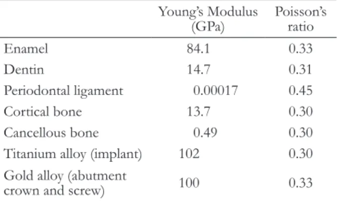
Table 2. Material properties
Young’s Modulus
(GPa) Poisson’s ratio
Enamel 84.1 0.33
Dentin 14.7 0.31
Periodontal ligament 0.00017 0.45
Cortical bone 13.7 0.30
Cancellous bone 0.49 0.30
Titanium alloy (implant) 102 0.30 Gold alloy (abutment
crown and screw) 100 0.33
Table 3. Maximum von Mises stress value (MPa) and location of each model
Maximum
von Mises stress Location NA 28.41 2
ndpremolar apex NN 51.57 2
ndpremolar apex
IA 882.40 2
ndpremolar fixture screw IN 888.28 2
ndpremolar fixture screw
Table 4. Maximum von Mises stress values of each component per models (MPa unit)
Cortical bone Cancellous bone Teeth Implant Screw Crown
NA 0.62 8.97 28.41
NN 1.36 16.33 51.57
IA 155.46 13.25 831.16 882.40 874.03
IN 145.00 14.387 831.34 888.28 876.59
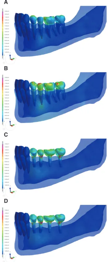
models showed relatively small difference in terms of maximum stress values on individual components between arbitrary and natural occlusion setups. The differences in values did not exceed 10% of greater values. The graphic demonstration of von Mises stress distribution pattern of different models are shown in Fig. 4.
The maximum displacement values and locations are listed in Table 5. The displacement value of natural teeth models differed according to occlusal setups. The location where maximum displacement occurred was also different. In arbitrary occlusion, 1
stpremolar buccal surface was most vulnerable to displacement while in natural occlusion, it was 2
ndmolar buccal surface. In implant models, the maxi- mum displacement values differed considerably as well as their location of maximum displacement. It was 1
stpremolar fixture screw area where maximum displacement occurred in the pearbitrary occlusion setup model (IA) whereas it was 1
stmolar fixture screw area for the natural occlusion setup model (IN).
Discussion
It was shown that different occlusal patterns lead to different results in terms of the stress distribution and displacement. This result was in agreement with other studies that indicated different loading pattern to have significant influence on the stress distribu- tion and subsequent outcome analysis.
5-13Therefore, providing an arbitrary loading condition for finite element analysis will have to be avoided as its result may not be close to real situation, especially when the study is aiming for a quantitative analysis of indi- vidual structure.
Fig. 4. Von Mises stress distribution pattern. (A) NA model, (B) NN model, (C) IA model, (D) IN model.
A
B
C
D
Table 5. Maximum displacement values (mm unit) and locations of each model
Maximum
displacement Location
NA 0.06 1
stpremolar buccal surface NN 0.08 2
ndmolar buccal surface
IA 0.26 1
stpremolar fixture screw
IN 0.41 1
stmolar fixture screw
There was a tendency that natural occlusion setup models (NN, IN) showed greater maximum von Mises stress and maximum displacement than arbi- trary occlusion setup models (NA, IA) despite the greater numbers in occlusal points in arbitrary occlu- sion setup. It could be attributed to the differential load distribution in natural occlusion setup models.
The concentrated load resulted in greater stress and distribution. In addition, the locations of maximum von Mises stress of each models remained constant throughout different occlusion setups. However, different occlusion setups lead to change in the loca- tions of maximum displacement.
Accura is developed as a digitalized occlusion mea- surement device with the capability of real-time mea- surement and data record.
20Its capability includes not only recording the occlusal point and force, but also the timing of the occlusion. Therefore, it can provide accurate individual occlusion data for the computer simulation such as finite element analysis or occlusal measurement related quantitative study.
Further development of this device into a neces- sary equipment in various dynamic analysis including computer simulation is expected.
The results of the present study showed that the variations in outcome were considerable and could not be considered as negligible. It can be assumed that the result of a single experimental modality may only represent a single situation and cannot be ap- plied as a universal interpretation of biomechanical behavior. The biomechanics of a treatment protocol can be affected by various factors, especially occlu- sal pattern, and therefore, its clinical performance prediction via finite element study may only deserve for limited validity. Based on the result of this study, it would be highly desirable in finite element analy- sis that various loading conditions both in terms of magnitude and distribution to be provided for realistic prediction of the results. Yet, there is little information regarding the sufficient range of vari- ous loading conditions to cover the real clinical situ- ations. Further studies would be required to decide the sufficient range of various loading conditions and occlusion in order to raise the predictability of finite element analysis in dentistry.
Conclusion
Different occlusal loading conditions lead to differ- ent stress distribution pattern. The Arbitrary occlu- sion and realistic occlusion that was acquired from Accura showed considerably different result in terms of maximum von Mises stress and maximum dis- placement level.
In finite element analysis, it is recommended to simulate with occlusal contact point and force that are based on accurate measurement.
Acknowledgements
This work was supported by SNU Brain Fusion Program of the Seoul National University in 2016.
This work was supported by the Seoul National Uni- versity Research Grant in 2016.
ORCID
Wonsup Lee https://orcid.org/0000-0003-4678-1001 Ghaith Alom https://orcid.org/0000-0001-6626-121X Myung-Soo Kim https://orcid.org/0000-0003-4755-5727 Young-Seok Park https://orcid.org/0000-0002-0148- 7848
Young-Jun Lim https://orcid.org/0000-0003-2504-9671 Myung-Joo Kim https://orcid.org/0000-0003-2020-5284 Ho-Beom Kwon https://orcid.org/0000-0003-4973-7727
References
1. Geng JP, Tan KB, Liu GR. Application of finite el- ement analysis in implant dentistry: a review of the literature. J Prosthet Dent 2001;85:585-98.
2. DeTolla DH, Andreana S, Patra A, Buhite R, Co- mella B. Role of the finite element model in dental implants. J Oral Implantol 2000;26:77-81.
3. Trivedi S. Finite element analysis: a boon to den- tistry. J Oral Biol Craniofac Res 2014;4:200-3.
4. Shetty P, Hegde AM, Rai K. Finite element meth- od-an effective research tool for dentistry. J Clin Pediatr Dent 2010;34:281-5.
5. Eskitascioglu G, Usumez A, Sevimay M, Soykan E,
Unsal E. The influence of occlusal loading location
on stresses transferred to implant-supported pros- theses and supporting bone: a three-dimensional finite element study. J Prosthet Dent 2004;91:144- 50.
6. Hernández-Vázquez RA, Romero-Ángeles B, Urriolagoitia-Sosa G, Vázquez-Feijoo JA, Vázquez- López ÁJ, Urriolagoitia-Calderón G. Numerical analysis of masticatory forces on a lower first mo- lar considering the contact between dental tissues.
Appl Bionic Biomech 2018:2018:4196343.
7. Benazzi S, Grosse IR, Gruppioni G, Weber GW, Kullmer O. Comparison of occlusal loading condi- tions in a lower second premolar using three-di- mensional finite element analysis. Clin Oral Investig 2014;18:369-75.
8. Brune A, Stiesch M, Eisenburger M, Greuling A.
The effect of different occlusal contact situations on peri-implant bone stress - a contact finite ele- ment analysis of indirect axial loading. Mater Sci Eng C Mater Biol Appl 2019;99:367-73.
9. Röehrle O, Saini H, Ackland DC. Occlusal loading during biting from an experimental and simulation point of view. Dent Mater 2018;34:58-68.
10. Chang Y, Tambe AA, Maeda Y, Wada M, Gonda T.
Finite element analysis of dental implants with vali- dation: to what extent can we expect the model to predict biological phenomena? A literature review and proposal for classification of a validation pro- cess. Int J Implant Dent 2018;4:7.
11. De Jager N, de Kler M, van der Zel JM. The influ- ence of different core material on the FEA-deter- mined stress distribution in dental crowns. Dent Mater 2006;22:234-42.
12. Kondo T, Wakabayashi N. Influence of molar sup- port loss on stress and strain in premolar periodon- tium: a patient-specific FEM study. J Dent 2009;37:
541-8.
13. Rand A, Stiesch M, Eisenburger M, Greuling A.
The effect of direct and indirect force transmission on peri-implant bone stress - a contact finite ele- ment analysis. Comput Methods Biomech Biomed Engin 2017;20:1132-9.
14. Cailleteau JG, Rieger MR, Akin JE. A comparison of intracanal stresses in a post-restored tooth utiliz- ing the finite element method. J Endodont 1992;18:
540-4.
15. Papavasiliou G, Kamposiora P, Bayne SC, Felton DA. Three-dimensional finite element analysis of stress-distribution around single tooth implants as a function of bony support prosthesis type and load- ing during function. J Prosthet Dent 1996;76:633- 40.
16. Ausiello P, Apicella A, Davidson CL. Effect of adhesive layer properties on stress distribution in composite restorations - a 3D finite element analy- sis. Dent Mater 2002;18:295-303.
17. Eskitascioglu G, Usumez A, Sevimay M, Soykan E, Unsal E. The influence of occlusal loading location on stresses transferred to implant-supported pros- theses and supporting bone: a three-dimensional finite element study. J Prosthet Dent 2004;91:144- 50.
18. Lanza A, Aversa R, Rengo S, Apicella D, Apicella A.
3D FEA of cemented steel glass and carbon posts in a maxillary incisor. Dent Mater 2005;21:709-15.
19. Mozayek RS, Allaf M, Abuharb MB. Efficacy of adding a supporting implant in stress distribution of long-span fixed partial dentures: a 3D finite element analysis. J Dent Res Dent Clin Dent Pros- pects 2016;10:81-6.
20. Jeong MY, Lim YJ, Kim MJ, Kwon HB. Compari- son of two computerized occlusal analysis systems for indicating occlusal contacts. J Adv Prosthodont 2020;12:49-54.
21. Coolidge ED. The thickness of the human peri- odontal membrane. J Am Dent Assoc 1937;24:1260- 70.
22. Yoshida N, Koga Y, Peng CL, Tanaka E, Kobayashi K. In vivo measurement of the elastic modulus of the human periodontal ligament. Med Eng Phy 2001;23:567-72.
23. Cattaneo PM, Dalstra M, Melsen B. The finite ele- ment method: a tool to study orthodontic tooth movement. J Dent Res 2005;84:428-33.
24. Moroi HH, Okimoto K, Moroi R, Terada Y. Nu- meric approach to the biomechanical analysis of thermal effects in coated implants. Int J Prostho- dont 1993;6:564-72.
25. Sano H, Ciucchi B, Matthews WG, Pashley DH.
Tensile properties of mineralized and demineralized
human and bovine dentin. J Dent Res 1994;73:1205- 11.
26. Farah JW, Craig RG, Meroueh KA. Finite element analysis of three- and four-unit bridges. J Oral Re- habil 1989;16:603-11.
27. Jones ML, Hickman J, Middleton J, Knox J, Volp C.
A validated finite element method study of orth- odontic tooth movement in the human subject. J Orthod 2001;28:29-38.
28. Tanne K, Yoshida S, Kawata T, Sasaki A, Knox J, Jones ML. An evaluation of the biomechanical response of the tooth and periodontium to orth- odontic forces in adolescent and adult subjects. Br J Orthod 1998;25:109-15.
29. Toms SR, Eberhardt AW. A nonlinear finite ele- ment analysis of the periodontal ligament under orthodontic tooth loading. Am J Orthod Dentofa- cial Orthop 2003;123:657-65.
30. Jung WK, Lee WS, Kwon HB. Effects of abutment screw preload in two implant connection systems: a 3D finite element study. J Prosthet Dent 2019;122:
474.e1-e8.
31. Silva GC, Cornacchia TM, de Magalhães CS, Bueno AC, Moreira AN. Biomechanical evaluation of screw-and cement-retained implant-supported prostheses: a nonlinear finite element analysis. J Prosthet Dent 2014;112:1479-88.
32. Quaresma SET, Cury PR, Sendyk WR, Sendyk C.
A finite element analysis of two different dental
implants: stress distribution in the prosthesis, abut- ment, implant, and supporting bone. J Oral Im- plantol 2008;34:1-6.
33. Wataha JC. Alloys for prosthodontic restorations. J Prosthet Dent 2002;87:351-63.
34. Jörn D, Kohorst P, Besdo S, Rücker M, Stiesch M, Borchers L. Influence of lubricant on screw pre- load and stresses in a finite element model for a dental implant. J Prosthet Dent 2014;112:340-8.
35. Inzana JA, Varga P, Windolf M. Implicit modeling of screw threads for efficient finite element analysis of complex bone-implant systems. J Biomech 2016;
49:1836-44.
36. Hsu ML, Chen FC, Kao HC, Cheng CK. Influence of off-axis loading of an anterior maxillary implant:
a 3-dimensional finite element analysis. Int J Oral Maxillofac Implants 2007;22:301-9.
37. Chang CL, Chen CS, Huang CH, Hsu ML. Finite element analysis of the dental implant using a to- pology optimization method. Med Eng Phys 2012;
34:999-1008.
38. Martin WC, Woody RD, Miller BH, Miller AW.
Implant abutment screw rotations and preloads for four different screw materials and surfaces. J Pros- thet Dent 20011;86:24-32.
39. Lang LA, Kang B, Wang RF, Lang BR. Finite ele-
ment analysis to determine implant preload. J Pros-
thet Dent 2003;90:539-46.
*교신저자: 권호범
(03080)서울시 종로구 대학로 101, 서울대학교 치의학대학원 치과보철과 및 치학연구소 Tel: 02-2072-3816|Fax: 02-2072-3860|E-mail: [email protected] 접수일: 2020년 5월 13일|수정일: 2020년 5월 30일|채택일: 2020년 6월 4일
하악 구치부에서 임의로 부여된 교합과 실제 교합의 삼차원 유한요소해석결과의 비교
이원섭
1대학원생, Ghaith Alom
1연구원, 김명수
2교수, 박영석
3교수, 임영준
4교수, 김명주
4교수, 권호범
4*
교수1
서울대학교 치의학대학원 치과보철과
2
서울대학교 공과대학 컴퓨터공학부
3
서울대학교 치의학대학원 구강해부학교실 및 치학연구소
4