Design of Shock Absorber Housing Using Aluminum Vacuum Die Casting Technology
8
0
0
전체 글
(2)
(3)
(4)
(5)
(6)
(7)
(8)
수치
관련 문서
In order to investigate the effects of process parameters on qualities of the drilled hole quantitatively, laser drilling experiments were carried out using
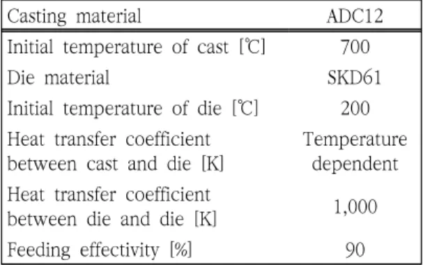
Casting is a manufacturing process by which a molten material such as metal or plastic is introduced into a mold made of sand or metal, allowed to solidify within the mold,
The solidification process of metal alloy was expressed by the change of solid fraction, and the solid fraction was controlled by varying size and
In this study, the reliability of high efficiency air conditioning compressor applied with high vacuum local pressure die casting technique is to be analyzed through
The positive change pattern of CK-MB according to time on acute myocardiac infarction patient.. The positive change pattern of troponin-T according to time on
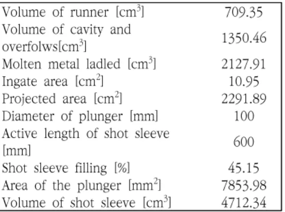
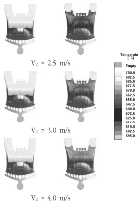
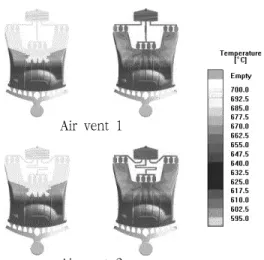
In terms of the mould design, the effects of runner system design and the mould temperature on filling characteristics, the weldline formation, the
Casting is a manufacturing process by which a molten material such as metal or plastic is introduced into a mold made of sand or metal, allowed to solidify within the mold,
When melting aluminum, if the generated hydrogen exceeds the critical solubility in the melt, the gas pressure increases during solidification.. Then pores
