원자력 발전소용 블레이드링 건전성 평가
박정용† · 정용근* · 박종진*· 강용호*
Integrity Assessment of Stationary Blade Ring for Nuclear Power Plant
Jung-Yong Park, Yong-Keun Chung, Jong-Jin Park and Yong-Ho Kang
Key Words : FAC(flow assisted corrosion), SCF(응력집중계수), Replica(미세조직채취), FEM(유한요 소해석), Thermal Transient Analysis(열천이해석), HP Stationary Blade(HP 고정익)
Abstract
The inner side between HP stationary blades in #1 turbine of Nuclear Power Plant A is damaged by the FAC(flow assisted corrosion) which is exposed to moisture. For many years the inner side is repaired by welding the damaged part, however, FAC continues to deteriorate the original material of the welded blade ring. In this study, we have two stages to verify the integrity of stationary blade ring in nuclear power plant A.
In the stage I, replication of blade ring is performed to survey the microstructure of blade ring. In the stage II, the stress analysis of blade ring is performed to verify the structural safety of blade ring. Throughout the two stages analysis of blade ring, the stationary blade ring had remained undamaged.
기호설명
Kt : 탄성 범위내의 이론적인 응력집중계수 h : 침식 깊이, r : 침식 반경
1. 서 론
원자력 발전소는 안전성이 우선시 되는 플랜트 특성을 가지고 있으므로 터빈의 주증기 온도와 압 력이 화력 발전소에 비해서 상당히 낮다. 그러므 로 습분이 발생되는 영역이 화력 발전소 보다 넓 게 분포되어 있다. 대략적인 습분의 수치는 대부 분의 원자력 터빈의 교축증기(Throttle Steam)에 서 습분이 거의 0에 가깝고 HP 터빈 Exhaust에 서 약 13%의 습분을 가진다.(1) 따라서 습분은 HP 터빈에서부터 발생됨으로써 터빈 전체에 걸쳐 서 취약한 부위나 재질에 손상이 자주 발생되고
습분 손실을 야기한다.
A원자력 발전소 1호기 터빈은 HP Stationary Blade 사이에 FAC(flow assisted corrosion)로 인해 블레이드 링의 손상이 발생되어 손상부위에 대한 보수 육성용접을 실시해 왔으나 보수 육성용 접 인접부에서 계속적으로 FAC로 인한 손상이 발생함으로써 손상진행을 억제하기 위해 금번 Overhaul 기간 중에 손상된 블레이드링의 코팅이 실시되었다. 손상된 블레이드 링에 대한 미세조직 평가와 응력해석 평가를 통하여 블레이드링의 소 재 건전성을 구조적인 측면에서 평가하는데 목적 이 있다.
2. 미세조직에 의한 건전성 평가
2.1 미세조직 채취
Replica 채취는 Fig.1 에서 보는 바와 같이 각 Stationary Stage 의 Downstream 영역의 블레이드링 에서 수행되었다. 이 영역은 운전 중 발생된 FAC 손상으로 인하여 탄소강 모재가 원주방향으로 깊 이 패여 있으며 제작시 형성된 인코넬 용접부와
† 두산중공업
E-mail : [email protected]
TEL : (055)278-3701 FAX : (055)278-8593
* 두산중공업
운전중 보수 용접부에서는 손상이 발생하지 않았 음을 보여주고 있다. Replica 는 인코넬 용접 열영 향부와 손상이 발생된 탄소강 모재가 포함되도록 채취되었다.
Fig. 1 The Location of Replication 2.1 미세조직 관찰
Fig.2 에서 보여주는 바와 같이 모재(base metal) 의 미세조직은 페라이트(ferrite, 흰색부위)와 Fe3C (cementite)의 혼합조직인 퍼얼라이트(pearlite, 검은 부위)로 구성되어 있음을 보여주고 있다. 퍼얼라 이트 내의 Fe3C 가 제작 초기의 형상으로 추정되 는 층상조직을 그대로 유지하고 있어 매우 건전함 을 보여주고 있다. 그렇지만 모재조직의 경우 각 영역에서 약간씩 차이를 보이고 있다. HP Governor Side 의 Upper 영역은 주조조직인 Dendrite 형상이 잔존하는 상태이고, HP Governor Side 의 Lower 영 역과 HP Generator Side 는 정상적인 정방형 입자 (equiaxed-grain) 형상을 보이고 있다. 또한 결정 입 자 크기에서 HP Governor Side 가 HP Generator Side 보다 상당히 크게 나타나고 있다. 동일 재질임에 도 불구하고 미세조직적 차이를 보이는 것은 주조 과정의 냉각속도가 위치에 따라 차이가 나기 때문 인 것으로 사료된다.
(a) Base Metal (b) Heat Affected Zone Fig. 2 The Microstructure of Lower Stage 8 in the
Governor Side
용접 열영향부의 미세조직은 전형적인 용접 열 영향부에서 보여주는 베이나이트(bainite)로 구성되 어 있음을 보여주고 있고, 봉상 형태의 베이나이 트가 그대로 존재하고 있어 열영향부 역시 미세조
직적으로 매우 안정한 것으로 추정되며, Martensite 의 발생 등으로 인한 취화는 나타나지 않은 것으 로 사료된다.
3. 응력해석에 의한 건전성 평가
3.1 응력해석 개요
FAC(flow assisted corrosion)가 발생된 블레이드링 의 건전성 여부를 FEM(finite element method)을 이 용한 상세 응력해석과 SCF(stress concentration factor)를 적용하여 평가하였다. A 원자력 발전소 1 호기 HP 터빈은 Governor 측과 Generator 측이 동 일한 증기 조건으로 운전되기 때문에 본 응력해석 에서는 Governor 측의 HP #1 블레이드링을 대상으 로 선정하였다.
3.2 운전 조건
블레이드링의 응력해석에 사용된 증기의 조건은 Table 1~2 와 같으며 A 원자력 발전소 1 호기 터빈 의 표준 기동곡선과 Heat Balance 를 기준으로 산 출하였다.
A 원자력 발전소 1 호기 터빈은 50% 반동 터빈 이므로 Governor 측 Stage 2 의 추기라인 압력과 Exhaust 의 압력을 균등하게 분배하여 Single Stage 압력을 산출하였으며 Steam Table 을 이용하여 이 에 상응하는 Stage 온도를 계산하였다.
Table 1 Every Stage Pressure of Blade Ring in the Governor Side according to Start-up Condition that is used in the FEM Analysis
Time(sec) 0 2,880 3,816 5,616 8,568 13800 Stg3
Noz.
Inlet
79.2 96.4 113.6 148 251.1 422.9
Stg3 Noz.
Exit
74.4 90.5 106.7 139.0 235.8 397.2
Stg4 Noz.
Inlet
69.6 84.7 99.8 130.0 220.5 371.4
Stg4 Noz.
Exit
64.8 78.8 92.9 121.0 205.2 345.7
Stg5 Noz.
Inlet
59.9 72.9 85.9 111.9 189.9 320.0
Stg5 Noz.
Exit
55.1 67.1 79.0 102.9 174.7 294.2
Stg6 Noz.
Inlet
50.3 61.2 72.1 93.9 159.4 268.5
Pressure(psi)
Stg6 Noz.
Exit
45.5 55.3 65.2 84.9 144.1 242.8
Stg7 Noz.
Inlet
40.7 49.5 58.3 75.9 128.8 217.0
Stg7 Noz.
Exit
35.8 43.6 51.4 66.9 113.6 191.3
Stg8 Noz.
Inlet
31.0 37.7 44.5 57.9 98.3 165.5
Stg8 Noz.
Exit
26.2 31.9 37.6 48.9 83.0 139.8
Table 2 Every Stage Temperature of Blade Ring in the Governor Side according to Start-up Condition that is used in the FEM Analysis
Time(sec) 0 2,880 3,816 5,616 8,568 13800 Stg3
Noz.
Inlet
84.3 102.6 120.9 157.4 267.2 450.0
Stg4 Noz.
Inlet
81.3 98.9 116.5 151.8 257.5 433.8
Stg5 Noz.
Inlet
78.2 95.2 112.2 146.1 247.9 417.6
Stg6 Noz.
Inlet
75.2 91.5 107.8 140.5 238.3 401.5
Stg7 Noz.
Inlet
72.2 87.8 103.5 134.8 228.7 385.3
Stg8 Noz.
Inlet
69.2 84.1 99.1 129.1 219.1 369.1
Temperature(deg. F)
Stg8 Noz.
Exit
66.1 80.4 94.8 123.5 209.5 352.9
3.3 해석조건
응력해석을 하기 위한 해석의 종류는 기동 시간 에 따른 열천이 해석(thermal transient analysis)으로 서 전체 노드(node)의 개수는 994 개이며 요소 (element)의 개수는 854 개이다. 해석을 하기위한 최적의 요소의 형태(element type)는 Axi-symmetric Thermal/Solid Element(Plane 55/Plane 42)이다.(2)
(a) The Contour of Blade Ring
(b) FEM of Blade Ring
Fig. 3 The Finite Element Analysis Model of Blade Ring
3.4 해석결과
3.4.1 과도상태 열응력 해석
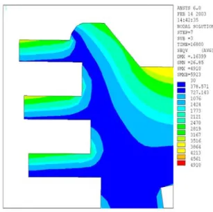
Governor 측의 HP #2 블레이드링에 대한 응력해 석 결과를 Fig. 4 에 나타내었다. 해석 결과 최대 열응력은 Stage 3 의 Back Side 에서 발생하였으며 응력의 크기는 4.819 ksi 로 계산 되었다. FAC(flow assisted corrosion)가 발생된 Nozzle 출구의 경우 최 대 열응력은 Stage 3 에서 발생하였으며 그 크기는 2.265 ksi 이다.
(a) The Result of Stress Analysis
(b) The Magnification of Stress Analysis (FAC Section)
Fig. 4 The Stress Analysis of Blade Ring in the HP Governor Side #2 during Start-up
3.4.2 SCF(Stress Concentration Factor)를 적용한 FAC 평가
일반적인 침식 손상은 Fig. 5 과 같이 발생하며 이때의 응력집중계수(SCF)는 식(1)과 같이 계산된 다.(3)
r h
Kt =0.855+2.21 (1)
Nozzle 출구에서 발생하는 FAC 를 반원형 침식 으로 가정하면 식(1)에서 h=r 이 된다. 그러므로 FAC 에 대한 SCF 는 Kt=3.065 로 산출된다.
Fig. 5 Stress Concentration Factor(notch in semi- infinite plate)
따라서 FAC 가 주로 발생된 부위의 응력은 ksi
942 6 065 3 265
2. × . = .
σ = 로 계산된다.
4. 건전성 평가 및 고찰
HP Stationary Blade 에 대한 구조물 응력해석과 SCF(stress concentration factor)를 이용한 계산 결과 Nozzle 출구의 응력이 재질의 피로 한도값(fatigue limit value)과 재질의 항복 강도값(Yield Strength value)에 비하여 매우 작으므로 FAC 가 발생되었 다 할지라도 매우 건전함을 보여주고 있다.(4)
Stage 3 의 해석 결과에 따른 피로수명 평가 내 용을 Table 3 에 나타내었다.
Table 3 The Analysis Results of Fatigue Life in the Governor Stage 3 Nozzle Exit
Location FAC Stress (Von-Mises)
Fatigue Limits
Yield Strength
× 2.265 ksi HP
Governor
Stage 3 O 6.942 ksi
35 ksi 44.0 ksi
Table 3 에서도 알 수 있듯이 FAC 가 존재하는 곳에서 피로한도 값의 약 19.8%에 해당하는 크기 로 존재하고 있으며 FAC 가 존재하지 않는 곳에 서는 약 6.47%에 해당하는 크기로 존재함으로써 구조물에 진동이 발생되더라도 아주 미미한 것으 로 판단이 된다. 또 항복 강도 측면에서 살펴보면 FAC 가 존재하는 곳에서 약 15.7%의 값으로 존재 하며 FAC 가 존재하지 않는 곳에서는 약 5.14%의 크기로 존재한다. 이값들도 피로한도 값과 마찬가 지로 구조물에 미치는 영향이 미미한 것으로 판단 이 된다. 따라서 응력해석적 측면에서 구조물에 대한 건전성을 평가했을 때 FAC 가 발생되더라도 구조물에는 영향이 미미한 것으로 판단이 된다.
5. 결 론
FAC 가 발생된 블레이드링의 건전성 여부를 FEM 을 이용한 상세 응력해석과 SCF 를 적용하여 평가한 결과 다음과 같은 결론을 얻었다.
(1) 모재의 미세조직은 페라이트와 퍼얼라이트로 구성된 전형적인 탄소강의 미세조직을 보여주 고 있으며 특히 퍼얼라이트는 제작 초기와 같 은 페라이트와 Fe3C 의 층상조직을 그대로 유 지하고 있어 매우 건전한 상태이므로 계속 사
용해도 문제는 없는 것으로 사료된다.
(2) 블레이드링에 대한 Transient Stress Analysis 를 수행한 결과 최대 응력은 Stage 3 과 Stage 4 사 이의 Back Side 에서 발생하였고 응력의 크기는 4.8ksi 로 계산 되었다. 침식이 발생된 Nozzle 출구의 경우 Back Side 의 최대응력 보다 낮은 응력이 발생되는 것으로 계산되고 이중 최대 응력은 Stage 3 에서 발생되었다. Stage 3 의 Nozzle 출구에 발생된 응력의 크기는 2.265 ksi 이다.
(3) FAC 에 따른 SCF(응력집중계수)는 3.065 로 계 산되었고 이 값을 Stage 3 의 Nozzle 출구에 적 용한 결과 6.94ksi 의 응력이 발생되는 것으로 계산되었다.
(4) 해석 결과 블레이드 링에 발생된 응력은 재질 의 피로한도인 35 ksi 와 재질의 항복강도인 44 ksi 보다 매우 낮으므로 블레이드링은 건전한 것으로 사료된다.
참고문헌
(1) Kenneth.C.Cotton,1994, “Evaluating and Improving Steam Turbine Performance”, Cotton Fact,pp.64-65 (2) ANSYS 6.0 Manual : Theory Manual, Element
Manual, Command Manual
(3) Walter D.Pilkey,1994,“Formulas for Stress, Strain and Structural Matrices”, John Wiley & Sons, Inc,pp.260-261
(4) Julie A. Bannantine, Jess J. Comer, James L.
Handrock,1990, “Fundamentals of Metal Fatigue Analysis”,Prentice Hall,Inc,pp.1-10