253
"J. Korean Soc. Radiol., Vol. 11, No. 4, August 2017"
A Study on the Accuracy and Convenience of Imaging Method Using Support Device in Knee Joint Lateral Radiography
Soyeong Uhm, Yongkeun Cho, Sungjin Kang*
Department of Radiology, Soonchunhyang University Bucheon Hospital
Received: July 13, 2017. Revised: August 19 , 2017. Accepted: August 31, 2017
ABSTRACT
In lateral projection imaging method of knee joint, a method that adjusts the incidence angle of central X-ray toward the head side to 5~7° in true lateral position which is existing recommended is called imaging method A, Method of imaging the central X-ray perpendicular to the horizontal plane of the examination table toward the knee is called imaging method B, and a method in which the central X-ray is perpendicularly applied to the joints while the lateral side of the distal tibia is compensated by radiolucent materials is called as method C. After tests each imaging method to classified study subject respectively, the joint space distance and the distance between lateral and medial condyle of femur were measured and compared as the quantitative index from the three imaging methods. In addition, the convenience of each imaging method was confirmed through questionnaires to practician. According to the result of the quantitative index, there is no statistically significant difference in imaging method A and C(p>0.05). However, imaging method B showed a significant difference in both A and C(p<0.05). As a result of evaluating the convenience of the imaging method, imaging method A was relatively assessed lower in all items than imaging methods B and C, and as a small difference, imaging method B is assessed higher than C. In this study suggested new knee joint lateral projection imaging method, by using a simple support device, could describe joint space as not much different as existing recommended method without some complex process, and could increase convenience of the practician in the process of the imaging.
Keywords: Knee Joint, Radiography, Support Device.
Ⅰ . INTRODUCTION
최근 들어 국민 소득 수준의 향상과 더불어 삶의 질에 대한 개선을 위하여 여가나 건강을 위한 목적 의 육체 활동이 증가하고 있다. 하지만 무리한 활 동으로 인한 관절 질환의 발생 비율도 증가하고 있 으며, 특히 여러 관절 중에서 체중의 부하가 큰 슬관절(k nee joint)은 다른 관절보다 많은 손상의 비중을 차지 하고 있다.[1]
슬관절의 영상의학적 평가는 주로 일반 X선 검 사방법이 접근성과 편의성이 높다는 이유로 가장 선행되는 평가 항목으로 이용되고 있으며, 그중에 서도 기본적으로 정면 촬영(anterior-posterior project ion)검사와 측면촬영(lateral projection) 검사방법을
이용하여 관절 구조물의 이상 유무를 평가하고 있
다.[2,3] 슬관절의 누운 자세(supine position) 정면촬
영 검사방법의 경우 해부학적 정면 자세에서 중심 X선이 대퇴-경골 관절 강(femoro-tibial joint space) 을 향하여 수직 입사하는 상태로 이루어지기 때문 에 정확한 영상을 얻기 위한 과정에 큰 어려움이 없는 편이다. 반면에 측면촬영 방법의 경우 옆으로 누운 자세(lateral recumbent position)에서 슬관절이 정 측면(true lateral) 상태가 유지 되어야 대퇴골(fe mur)의 내과(medial condyle)와 외과(lateral condyle) 가 최대한 겹쳐지게 되며, 또한 관절 강 내부가 최 대한 겹침 없이 묘사되기 위해 무릎을 20~30° 정도 구부린(flexion) 채로 중심 X선을 머리 쪽 5~7°로 각 도를 주어야 하는 다소 복잡한 과정이 필요하다.
현재 보편적으로 사용되고 있는 일반촬영용 X선
* Corresponding Author: Sungjin Kang E-mail: [email protected] Tel: +82-32-621-6566 https://doi.org/10.7742/jksr.2017.11.4.253
장치는 검사 테이블 하단에 이동형 격자(bucky gri d)와 상수용체(image receptor)가 수납되어 있는 상 태이다. 일부의 장치를 제외하고는 중심 X선이 검 사 테이블과 일정한 각도를 이루고 입사할 경우 상 수용체 중앙에 중심선을 일치시키는 과정을 한눈 에 파악하는데 불편함이 있기 때문에 중심 X선의 입사 각도를 조정하는 과정을 생략하고 검사를 진 행하는 경우가 종종 발생한다. 이러한 경우, 영상에서 기하학적 인자에 의한 관절면의 왜곡(distortion)이 증 가하여 슬관절의 이상 평가를 위한 정확한 묘사에 제한점이 될 수 있다.
본 연구는 슬관절의 측면촬영 검사방법에서 기 존에 권고되고 있는 중심 X선의 입사 각도를 머리 쪽 5~7°로 조정하는 방법을 기준으로, 경골 원위부 (distal tibia)의 바깥 면(lateral side)을 방사선 투과성 물질(radiolucent materials)로 보상한(compensated) 상 태에서 중심 X선을 관절 강에 수직 입사하는 방법을 적용한 후 검사하고, 이를 비교하여 정확한 대퇴- 경골 관절 강의 묘사를 위한 간단한 촬영 방법을 제안해 보고자 하였다.
Ⅱ. MATERIAL AND METHODS
1. 대상
2017년 1월 1일부터 2017년 5월 31일 까지 본원 에서 슬관절 방사선 검사를 시행한 환자 중 90명을 선별하여 이들의 슬관절 측면 영상(우측 37 예, 좌 측 53 예)을 평가 대상으로 하였다.
대상자의 성비는 남자 49명, 여자 41명 이었고, 평 균연령은 40세(연령범위 17~65)였다. 사용 장비로 는 디지털 X선 촬영 장치(Discovery XR656, GE He althcare, Beijing, China)를 이용하였으며, 촬영조건 으로는 관전압 65 ㎸p, 관전류 250 ㎃, 조사시간 40
㎳로 설정하여 검사를 시행하였다.
2. 검사 보조기구(support device)의 제작
연구를 위하여 자체적으로 보조기구를 제작하였 다. 보조기구는 방사선 감약계수(attenuation coeffici ent)가 극히 낮은 방사선 투과성 압축 폴리스티렌(p olystyrene)을 이용하여 장축 25 ㎝, 단축 15 ㎝, 높
이 7 ㎝, 바닥면과 5~7° 범위의 경사를 갖는 쐐기(w edge) 모양으로 절단하여 제작하였다. Fig. 1은 실제 제작된 보조기구의 모습이다.
Fig. 1. Manufacture of support device of knee joint lateral projection imaging using compressed polystyrene.
3. 방법
모든 대상자들은 옆으로 누운 자세(lateral recumb ent position)에서 슬관절 측면촬영 검사를 시행하였 다. 검사를 위한 자세와 장치의 기하학적 배열은 다음의 3가지 검사방법을 적용하였다.
3.1 검사방법 A
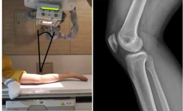
검사방법 A는 Fig. 2에서처럼 정 측면 자세에서 중심 X선이 슬관절 강(knee joint space)을 향해 검 사대의 수평면과 머리 쪽으로 5°의 각도를 유지하 여 입사하였다.
Fig. 2. Imaging method A is adjusts the incidence angle of central X-ray toward the head side to 5~7°
toward knee joint in true lateral position.
3.2 검사방법 B
검사방법 B는 Fig. 3에서처럼 정 측면 자세에서 중심 X선이 슬관절 강을 향해 검사대의 수평면과
"J. Korean Soc. Radiol., Vol. 11, No. 4, August 2017"
수직으로 입사하였다.
Fig. 3. Imaging method B is imaging the central X-ray perpendicular to the horizontal plane of the examination table toward the knee joint in true lateral position.
3.3 검사방법 C
검사방법 C는 Fig. 4에서처럼 경골 원위부의 바 깥쪽 면을 보조기구로 보상하여 경골의 장축이 검 사대의 수평면에 대해 5° 정도의 각도를 유지시킨 후 중심 X선이 슬관절 강을 향해 검사대의 수평면 과 수직으로 입사하였다.
Fig. 4. Imaging method C is central X-ray is
perpendicularly applied to the knee joint in true lateral position while the lateral side of the distal tibia is compensated by radiolucent materials(dotted arrow).
4. 평가
정량적 평가를 위해 검사방법 A, B, C를 각각 적 용한 영상에서 대퇴골과(femoral condyle)와 경골 고 평부(tibial plateau)가 마주보는 가장 좁은 부위의 간격을 관절 강 거리(joint space distance)로 정의하 였고, 대퇴골 내·외측과의 상·하 방향 이격거리를 양측과의 거리(both condyle distance)로 정의하여 정 량적 측정 지표로 비교 하였다.
이때 정확한 평가를 위하여 각각의 검사방법에 서 대퇴골의 내·외측과의 전·후 방향 겹침이 2 ㎜ 이내로 충분한 정 측면(true lateral) 자세를 유지하 였다고 판단되는 검사 영상 각 30 예(case) 씩, 총 9 0 사례의 검사 영상을 선별한 후 비교 평가에 사용 하였다.
모든 정량적 지표의 측정은 Digital imaging viewi ng system(Deja-view)의 측정도구(distance bar)를 사 용하여 2명의 관찰자가 각각 독립적으로 측정한 후 그 평균값을 이용하였다.
측정된 지표 값들은 각 검사 방법 간의 상관관계를 알아보기 위하여 mann whitney U test를 시행하였다.
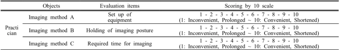
통계적 분석 도구로는 SPSS for windows(Version 14; SPSS Inc, Chicago, Illinois)를 이용하였고, p<0.0 5 일 경우 유의하다고 판정하였다. 또한 각 검사방 법에 따른 상대적인 편의성(convenience)을 평가하 기 위하여 Table 1의 설문조사표를 이용하여 각각 의 검사방법을 모두 시행한 3명의 검사자(practicia n)에게 검사장치의 준비와 배열, 검사 자세의 유지, 검사 소요시간의 3 가지 항목에 대하여 1: 불편하 다(inconvenient), 길다(prolonged) 부터 10: 편하다(co nvenient), 짧다(shortened)의 10점 척도를 이용한 설 문조사를 시행하였다.
Table 1. Questionnaire for evaluating convenience of imaging method A, B, C in knee lateral imaging
Objects Evaluation items Scoring by 10 scale
Practi cian
Imaging method A Set up of equipment
1 - 2 - 3 - 4 - 5 - 6 - 7 - 8 - 9 - 10 (1: Inconvenient, Prolonged ~ 10: Convenient, Shortened) Imaging method B Holding of imaging posture 1 - 2 - 3 - 4 - 5 - 6 - 7 - 8 - 9 - 10
(1: Inconvenient, Prolonged ~ 10: Convenient, Shortened) Imaging method C Required time for imaging 1 - 2 - 3 - 4 - 5 - 6 - 7 - 8 - 9 - 10
(1: Inconvenient, Prolonged ~ 10: Convenient, Shortened) Note. Imaging method A: Adjusts the incidence angle of central X-ray toward the head side to 5~7° toward knee joint in true lateral position, Imaging method B: Imaging the central X-ray perpendicular to the horizontal plane of the examination table toward the knee joint in true lateral position, Imaging method C: Central X-ray is perpendicularly applied to the knee joint in true lateral position while the lateral side of the distal tibia is compensated by support device.
Ⅲ. RESULT
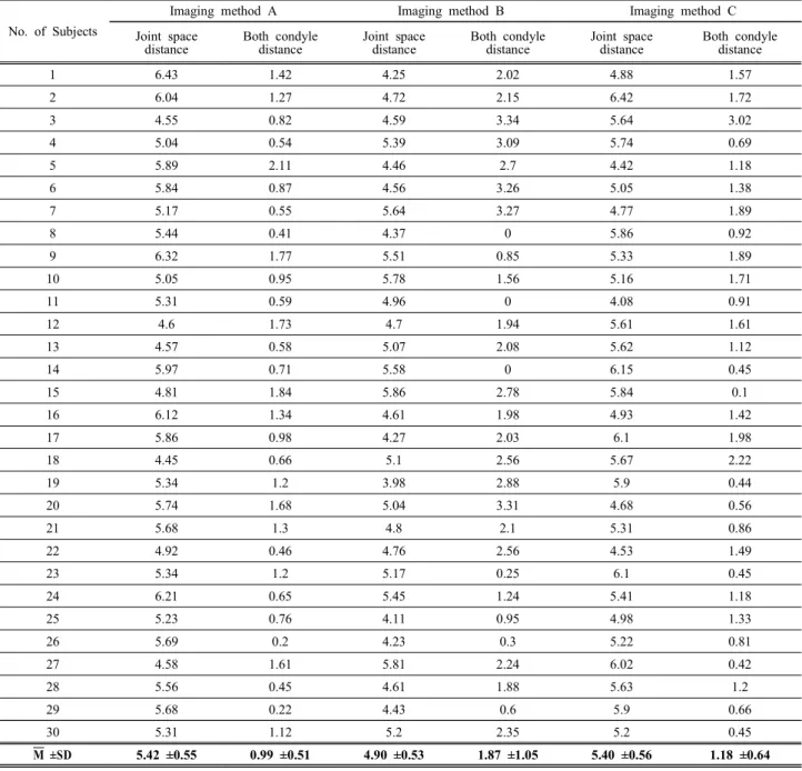
각 검사방법에 대한 정량적 지표의 측정 결과는 다음의 Table 2와 같다.
Table 2. Measurement results of quantitative index by imaging method
No. of Subjects
Imaging method A Imaging method B Imaging method C
Joint space distance
Both condyle distance
Joint space distance
Both condyle distance
Joint space distance
Both condyle distance
1 6.43 1.42 4.25 2.02 4.88 1.57
2 6.04 1.27 4.72 2.15 6.42 1.72
3 4.55 0.82 4.59 3.34 5.64 3.02
4 5.04 0.54 5.39 3.09 5.74 0.69
5 5.89 2.11 4.46 2.7 4.42 1.18
6 5.84 0.87 4.56 3.26 5.05 1.38
7 5.17 0.55 5.64 3.27 4.77 1.89
8 5.44 0.41 4.37 0 5.86 0.92
9 6.32 1.77 5.51 0.85 5.33 1.89
10 5.05 0.95 5.78 1.56 5.16 1.71
11 5.31 0.59 4.96 0 4.08 0.91
12 4.6 1.73 4.7 1.94 5.61 1.61
13 4.57 0.58 5.07 2.08 5.62 1.12
14 5.97 0.71 5.58 0 6.15 0.45
15 4.81 1.84 5.86 2.78 5.84 0.1
16 6.12 1.34 4.61 1.98 4.93 1.42
17 5.86 0.98 4.27 2.03 6.1 1.98
18 4.45 0.66 5.1 2.56 5.67 2.22
19 5.34 1.2 3.98 2.88 5.9 0.44
20 5.74 1.68 5.04 3.31 4.68 0.56
21 5.68 1.3 4.8 2.1 5.31 0.86
22 4.92 0.46 4.76 2.56 4.53 1.49
23 5.34 1.2 5.17 0.25 6.1 0.45
24 6.21 0.65 5.45 1.24 5.41 1.18
25 5.23 0.76 4.11 0.95 4.98 1.33
26 5.69 0.2 4.23 0.3 5.22 0.81
27 4.58 1.61 5.81 2.24 6.02 0.42
28 5.56 0.45 4.61 1.88 5.63 1.2
29 5.68 0.22 4.43 0.6 5.9 0.66
30 5.31 1.12 5.2 2.35 5.2 0.45
M ±SD 5.42 ±0.55 0.99 ±0.51 4.90 ±0.53 1.87 ±1.05 5.40 ±0.56 1.18 ±0.64
Note. Imaging method A: Adjusts the incidence angle of central X-ray toward the head side to 5~7° toward knee joint in true lateral position, Imaging method B: Imaging the central X-ray perpendicular to the horizontal plane of the examination table toward the knee joint in true lateral position, Imaging method C: Central X-ray is perpendicularly applied to the knee joint in true lateral position while the lateral side of the distal tibia is compensated by support device, M: Mean value, SD: Standard deviation, Units: ㎜.
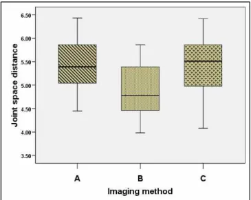
Fig. 5 는 각각의 검사방법에서 측정한 관절 강 거리의 평균과 표준편차 값을 나타낸다. 검사방법 A가 5.42 ±0.55, 검사방법 B가 4.90 ±0.53, 검사방법 C가 5.40 ±0.56 이었다.
Fig. 6 은 양측과의 거리의 평균과 표준편차 값을 나타낸다. 검사방법 A가 0.99 ±0.51, 검사방법 B가 1.87 ±1.05, 검사방법 C가 1.18 ±0.64 이었다.
"J. Korean Soc. Radiol., Vol. 11, No. 4, August 2017"
Fig. 5. A box plot chart comparing the measured values of joint space distance according to the imaging method.
Imaging method A: Adjusts the incidence angle of central X-ray toward the head side to 5~7° toward knee joint in true lateral position, Imaging method B: Imaging the central X-ray perpendicular to the horizontal plane of the examination table toward the knee joint in true lateral position, Imaging method C: Central X-ray is perpendicularly applied to the knee joint in true lateral position while the lateral side of the distal tibia is compensated by support device.
Fig. 6. A box plot chart comparing the measured values of both condyle distance according to the imaging method.
Imaging method A: Adjusts the incidence angle of central X-ray toward the head side to 5~7° toward knee joint in true lateral position, Imaging method B: Imaging the central X-ray perpendicular to the horizontal plane of the examination table toward the knee joint in true lateral position, Imaging method C: Central X-ray is perpendicularly applied to the knee joint in true lateral position while the lateral side of the distal tibia is compensated by support device.
Mann whitney U test를 이용한 검사방법 간의 상 관관계를 분석한 결과는 다음의 Table 3과 같다.
관절 강 거리 측정결과의 통계적 유의성 검증은 검사방법 A와 B가 0.001, A와 C가 0.871, B와 C가
0.001 이었다. 검사방법 A와 C 사이에는 측정 결과 에 특징적인 차이가 없었지만(p>0.05), 검사방법 B 는 A와 C 두 가지에서 모두 차이가 있었다(p<0.05).
양측과의 거리 측정결과는 검사방법 A와 B가 0.00
1, A와 C가 0.34, B와 C가 0.004 이었다. 관절 강 거리의 유의성 검증과 동일하게 검사방법 A와 C 사이에는 측정 결과에 별다른 차이가 없었지만(p>
0.05), 검사방법 B는 A와 C 두 가지에서 모두 차이 가 있었다(p<0.05). 검사방법에 대한 검사자의 편의 성을 평가하기 위한 설문 결과에서 검사자들의 응 답 평균값은 다음의 Table 4와 같다.
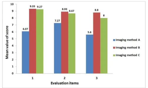
Fig. 7 은 3명의 검사자들을 대상으로 한 검사방 법의 상대적 편의성을 묻는 설문 결과를 나타낸다.
검사장치의 준비와 배열, 검사 자세의 유지, 검사 소요시간의 항목에 대한 평균과 표준편차 값은 검 사방법 A가 각각 6.07 ±0.68, 7.27 ±0.93, 5.60 ±0.80, 검사방법 B가 9.33 ±0.47, 8.93 ±0.57, 8.80 ±0.54, 검 사방법 C가 9.27 ±0.44, 8.67 ±0.60, 8.00 ±0.97 이었 다.
검사방법 A가 모든 항목에서 검사방법 B, C 보 다 상대적으로 점수가 낮게 평가되었고, 검사방법 B와 C는 근소한 차이로 B가 높은 평가를 받았다.
Table 3. The result of correlation analysis between imaging methods using Mann whitney U test statistical
significance
Imaging method A versus B
Imaging method A versus C
Imaging method B versus C p value using by
joint space distance value 0.001 0.871 0.001
p value using by
both condyle distance value 0.001 0.34 0.004
Note. Imaging method A: Adjusts the incidence angle of central X-ray toward the head side to 5~7° toward knee joint in true lateral position, Imaging method B: Imaging the central X-ray perpendicular to the horizontal plane of the examination table toward the knee joint in true lateral position, Imaging method C: Central X-ray is perpendicularly applied to the knee joint in true lateral position while the lateral side of the distal tibia is compensated by support device. (p-value was less than 0.05).
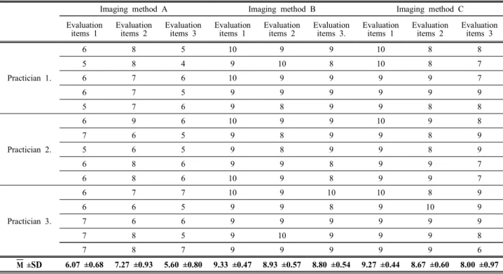
Table 4. The result of a questionnaire for evaluating the convenience of the practician for imaging methods A, B, and C in the knee lateral imaging
Imaging method A Imaging method B Imaging method C
Evaluation items 1
Evaluation items 2
Evaluation items 3
Evaluation items 1
Evaluation items 2
Evaluation items 3.
Evaluation items 1
Evaluation items 2
Evaluation items 3
Practician 1.
6 8 5 10 9 9 10 8 8
5 8 4 9 10 8 10 8 7
6 7 6 10 9 9 9 9 7
6 7 5 9 9 9 9 9 9
5 7 6 9 8 9 9 8 8
Practician 2.
6 9 6 10 9 9 10 9 8
7 6 5 9 8 9 9 8 9
5 6 5 9 8 9 9 8 9
6 8 6 9 9 8 9 9 7
6 8 6 10 9 8 9 9 7
Practician 3.
6 7 7 10 9 10 10 8 9
6 6 5 9 9 8 9 10 9
7 6 6 9 9 9 9 9 9
7 8 5 9 10 9 9 9 8
7 8 7 9 9 9 9 9 6
M ±SD 6.07 ±0.68 7.27 ±0.93 5.60 ±0.80 9.33 ±0.47 8.93 ±0.57 8.80 ±0.54 9.27 ±0.44 8.67 ±0.60 8.00 ±0.97 Note. Imaging method A: Adjusts the incidence angle of central X-ray toward the head side to 5~7° toward knee joint in true lateral position, Imaging method B: Imaging the central X-ray perpendicular to the horizontal plane of the examination table toward the knee joint in true lateral position, Imaging method C: Central X-ray is perpendicularly applied to the knee joint in true lateral position while the lateral side of the distal tibia is compensated by support device. Evaluation items 1: Set up of equipment, Evaluation items 2: Holding of imaging posture, Evaluation items 3: Required time for imaging, M: Mean value, SD: Standard deviation.
"J. Korean Soc. Radiol., Vol. 11, No. 4, August 2017"
Fig. 7. A bar chart comparing of result of a questionnaire for evaluating the convenience of the practician for imaging methods A, B, and C in the knee lateral imaging. Imaging method A: Adjusts the incidence angle of central X-ray toward the head side to 5~7° toward knee joint in true lateral position, Imaging method B: Imaging the central X-ray perpendicular to the horizontal plane of the examination table toward the knee joint in true lateral position, Imaging method C: Central X-ray is perpendicularly applied to the knee joint in true lateral position while the lateral side of the distal tibia is compensated by support device. Evaluation items 1: Set up of equipment, Evaluation items 2: Holding of imaging posture, Evaluation items 3: Required time for imaging.
Ⅳ. DISCUSSION
슬관절은 대퇴골, 경골(tibia), 슬개골(patella)로 구 성되어 있으며, 대퇴-경골 관절과 슬개-대퇴관절(pa tello-femoral joint)로 구분할 수 있다. 인체 내에서 가장 큰 관절이지만, 비교적 편평한 경골 상단 관 절 면에 둥근 모양인 대퇴골 관절융기(femoral cond yle)의 관절 면이 접촉하고 있기에 불안정하며 체중 에 의한 부하가 많은 관절이다. 슬관절의 안정성은 주위의 인대(ligament)나 근육들에 의하여 유지되고 있다. 슬관절은 사용하는 빈도도 높을 뿐만 아니라 체중에 의한 부하나 외력을 받기 쉬운 하지의 중간 에 위치하기 때문에 운동 손상(sports injury), 교통 사고(trauma)나 추락(fall down) 등의 외력에 의하여 인대나 반월상 연골(meniscus) 손상 등이 빈번하며, 각종 면역 질환 및 퇴행성 질환의 이환이 높은 관 절이다.
2016년 국민건강보험공단 건강보험정책연구원에 서다 빈도 수술 질환별 순위를 공개한 결과에서 보 면, 2006년 10위였던 슬관절 질환이 2015년 6위로
대폭 상승하였고, 최근 10년 동안 건강보험 및 의 료급여 청구 자료 중 슬관절 수술 환자 자료를 분 석한 결과, 2006년 25,414건에서 2015년 54,024 건 으로 2.13배(연평균 20.8%)증가하였다.[5] 따라서 슬 관절의 손상에 대한 의학적 소견과 치료과정에서 의 경과 관찰을 위하여 영상의학적 평가는 매우 중 요하게 여겨지고 있으며, 그 이용 빈도 역시 가파 르게 증가하고 있다.
영상의학적 검사는 슬관절의 질환에 대한 역학 조사에 가장 많이 이용되는 중요한 검사 항목 중의 하나이다. 슬관절의 검사방법에는 일반 X선(simple X-ray) 검사[6], 관절강 조영술(arthrography)[7], 관절 경(arthroscopy) 검사[8], 컴퓨터 단층 촬영(CT; comp uted tomography)[9], 자기공명영상(MRI; magnetic res onance imaging)[10] 등 여러 가지 방법이 이용된다.
관절강 조영술은 비교적 간단히 검사를 할 수 있 다. 하지만 검사방법이 침습적이며, 손상 부위만을 정확히 촬영하기 어렵고 오진율이 높아 현재는 이 용률이 극히 미비하다. 관절경 검사는 비교적 정확 하고 치료까지 가능하다는 장점이 있는 반면, 입원
과 마취 등으로 시간적, 경제적인 부담이 동반된다.
CT는 뼈에 이상(bony structure lesion)이 있는 경우 는 진단적으로 많은 도움이 되나 그 외 인대 손상 이나 반월상 연골손상의 평가에는 큰 도움이 되지 않는다. MRI는 비침습적 검사방법으로 상처나 고 통 없이 내부 구조의 정확한 진단이 가능하며, 뼈 에 타박상(contusion)이나 피하출혈(hypodermal blee ding)까지도 진단이 가능하다. 하지만 검사 소요시 간이 길며, 검사 비용도 높기 때문에 환자에게 부 담이 된다는 단점이 있다.[11] 일반 X선 검사는 슬관 절을 구성하는 다양한 연부조직의 직접적 묘사는 어렵지만 골 구조물의 위치나 상태를 바탕으로 기 하학적 측정을 통해 질환의 유추가 가능하다. 또한 앞서 소개한 여러 가지 영상의학적 검사방법에 비 해 짧은 시간 내에 검사가 가능하며, 환자에게 경 제적으로 큰 부담 없이 수술 전․후의 비교나 퇴행 성 변화에 대한 반복적 추적 검사가 가능하다.
일반적으로 슬관절 측면촬영 방법으로 권고되고 있는 중심 X선을 머리 쪽으로 5~7° 로 입사하게 하 는 검사방법은 대퇴-경골 관절 강을 가장 정확히 묘사하는 방법이라고 알려져 있다. 이를 이용하여 슬관절 전 치환술(total knee replacement) 시 굴곡에 대한 관절 운동 범위 평가의 기준이 되는 후경사각 (posterior slope angle)의 측정 및 무릎의 역학기전 장애를 유발하며 퇴행성관절염을 일으킬 수 있는 위험 요인인 반월상 연골 파열을 판단할 수 있는 지표로 이용되고 있다.[12-14] 따라서 이들 지표의 정 확한 평가를 위해서는 촬영 단계에서 정확한 검사 방법의 적용이 필요하다. 하지만 앞서 설명한 국민 건강보험공단 통계와 같이 슬관절 질환 환자의 증 가와 더불어 이들을 대상으로 하는 영상의학적 검 사의 업무량도 비례적으로 증가하는 관계로 매 검 사의 시행마다 정확한 검사방법을 준수하지 못한 채로 시행하는 경우가 종종 발생한다. 이러한 상황 은 슬관절 질환의 상태나 경과를 관찰하거나 평가 하기 위한 목적에 부합하지 못한 결과를 초래하게 된다. 본 연구자들은 이러한 상황을 극복하기 위해 관절강의 정확한 묘사에는 크게 차이가 없으면서 도 검사방법을 단순화하여 편의성을 개선 할 수 있 는 방법을 제안해 보고자 하였다.
연구 결과를 통해 정량적 지표로 정의하였던 관 절강의 거리 및 양측과의 거리는 기존에 권고되고 있는 슬관절 측면 촬영 검사방법과 본 연구에서 제 시한 보조기구를 사용한 검사방법을 비교하였을 때 통계적으로 유의미한 차이가 없다는 결과를 확 인할 수 있었다. 또한 그 방법의 적용에 있어서도 큰 무리가 없어 검사자들로 하여금 검사방법의 편 의성도 충분히 개선할 수 있었다고 평가 할 수 있 다. 다만 본 연구과정에서 정량적 지표의 측정이 실제 환자들을 대상으로 하였기에 동일한 대상에 게 각각의 검사방법을 적용하여 비교 관찰이 이루 어 지지 못한 부분 및 평가 대상자들의 수가 적고 연령대의 분포범위가 넓어 대상자의 퇴행성 과정 에 따른 관절강의 크기 변화를 고려하지 못한 부분 은 이 연구의 제약이 될 수 있다.
Ⅴ. CONCLUSION
본 연구를 통해 제안한 간단한 보조기구를 이용 한 슬관절 측면 촬영 검사방법은 다소 복잡한 준비 과정 없이도 기존의 권고 방법과 큰 차이가 없는 관절강의 묘사가 가능하고, 검사의 진행에 있어서 도 검사자의 편의성을 증가시킬 수 있는 효과를 확 인할 수 있었다. 이를 통해 보다 간편한 방법으로 슬관절 상태에 대한 정확한 평가 정보를 제공할 수 있을 것이다.
Reference
[1] H. J. Mankin, "The response of articular cartilage to mechanical injury," Journal of Bone & Joint Surgery- American Volume, Vol. 64, Issue 3, pp. 460-466, 1 982.
[2] N. H. Choi, J. H. Lee, "Evaluation of patellofemoral joint disorder," Journal of Korean orthopaedic society for sports medicine, Vol. 5, No. 1, pp. 17-21, 2006, in Korean.
[3] T. J. Ahn, J. K. Kim, B. W. Ahn, C. H. Park, "Stan dardization of Preoperative Radiography for Total Kn ee Arthroplasty," Knee surgery & related research, V ol. 6, No. 2, pp. 158-164, 1994.
[4] T. R. McAdams, K. Mithoefer, J. M. Scopp, B. R.
Mandelbaum, "Articular Cartilage Injury in Athletes,"
"J. Korean Soc. Radiol., Vol. 11, No. 4, August 2017"
Cartilage. Vol. 1, Issue 3, pp. 165-179, 2010.
[5] http://stat.kosis.kr/nsieu/view/tree.do?task=branchView&
hOrg=350&id=350_35004*MT_OTITLE&hOrg=350
[6] T. E. McAlindon, S. Snow, C. Cooper, P. A. Dieppe,
"Radiographic patterns of osteoarthritis of the knee jo int in the community: the importance of the patellofe moral joint," Annals of the Rheumatic Diseases, Vol.
51, pp. 844-849, 1992.
[7] C. J. P. Thijn, "Accuracy of double-contrast arthrogra phy and arthroscopy of the knee joint," Skeletal Radi ology, Vol. 8, Issue 3, pp. 187-192, 1982.
[8] F. R. Noyes, C. L. Stabler, "A system for grading ar ticular cartilage lesions at arthroscopy," American Jou rnal of Sports Medicine, Vol. 17, No. 4, pp. 505-51 3, 1989.
[9] M. L. Purnell, A. I. Larson, W. Clancy, "Anterior Cr uciate Ligament Insertions on the Tibia and Femur a nd Their Relationships to Critical Bony Landmarks U sing High-Resolution Volume-Rendering Computed To mography," The American Journal of Sports Medicin e, Vol. 36, Issue 11, pp. 2083-2090, 2008.
[10] R. Kijowski, A. Lu, W. Block, T. Grist, "Evaluation of the articular cartilage of the knee joint with vastl y undersampled isotropic projection reconstruction ste ady-state free precession imaging," Journal of Magne tic Resonance Imaging, Vol. 24, No. 1, pp. 168-175, 2006.
[11] R. F. LaPrade, B. K. Konowalchuk, H. M. Fritts, F.
A. Wentorf, "Articular Cartilage Injury of the Knee,"
The Physician and sportsmedicine, Vol. 29, No. 5, p p. 53-59, 2001.
[12] H. D. Clarke, W. N. Scott, J. N. Insall, Anatomy, I nsall JN, Scott WN editors, Surgery of the knee, 3r d edition, New York, Churchill Livingstone Inc., pp.
13-76, 2001.
[13] C. C. Jiang, K. M. Yip, T. K. Liu, "Posterior slope angle of the medial tibial plateau," Journal of the F ormosan Medical Association, Vol. 93, No. 6, pp. 5 09-512, 1994.
[14] A. A. Hofmann, K. N. Bachus, R. W. Wyatt, "Effec t of the tibial cut on subsidence following total kne e arthroplasty," Clinical Orthopaedics & Related Res earch, No. 269, pp. 63-69, 1991.
슬관절의 측면 방사선 촬영에서 보조기구를 이용한 검사방법의 정확성과 편의성에 대한 연구
엄소영, 조용근, 강성진* 순천향대학교 부속 부천병원 영상의학과
요 약
슬관절의 측면 촬영 검사방법에서 기존에 권고되고 있는 정 측면 자세에서 중심 X선의 입사 각도를 머 리 쪽 5~7°로 조정하는 방법을 검사방법 A, 중심 X선이 슬관절 강을 향해 검사대의 수평면과 수직으로 입 사하는 방법을 검사방법 B, 경골 원위부(distal tibia)의 바깥 면(lateral side)을 방사선 투과성 물질(radiolucent materials)로 보상한(compensated) 상태에서 중심 X선을 관절 강에 수직 입사하는 방법을 검사방법 C로 분류 하였다. 연구 대상자들을 분류하여 3가지 검사방법을 각각 시행한 후, 검사영상에서 관절 강 거리(joint spac e distance)와 양측과의 거리(both condyle distance)를 정량적 지표로 설정하여 이를 측정하고 비교하였다. 또 한 각 검사방법의 편의성을 검사자(Practician)들을 대상으로 설문조사를 통해 확인하였다. 정량적 지표의 측정 결과 검사방법 A와 C는 통계적 분석 결과 특징적인 차이가 없었지만(p>0.05), 검사 방법 B는 A와 C 모두에서 차이를 보였다(p<0.05). 검사방법의 편의성을 평가한 결과, 검사방법 A가 모든 항목에서 검사방법 B, C 보다 상대적으로 점수가 낮게 평가되었고, 검사방법 B와 C는 근소한 차이로 B가 높은 평가를 받았다.
본 연구를 통해 제안한 간단한 보조기구(support device)를 이용한 슬관절 측면 촬영 검사방법은 다소 복잡 한 준비과정 없이도 기존의 권고 방법과 큰 차이가 없는 관절 강의 묘사가 가능하고, 검사의 진행과정에서 검사자의 편의성을 증가시킬 수 있었다.
중심단어: 슬관절, 방사선 촬영, 보조기구