공간지능화에서 다중카메라를 이용한 이동로봇의 인간추적행위
Human-Tracking Behavior of Mobile Robot Using Multi-Camera System in a Networked ISpace
진 태 석
1
, 하시모토 히데키2
TaeSeok Jin1
, Hideki Hashimoto2
Abstract The paper proposes a human-following behavior of mobile robot and an intelligent space (ISpace) is used in order to achieve these goals. An ISpace is a 3-D environment in which many sensors and intelligent devices are distributed. Mobile robots exist in this space as physical agents providing humans with services. A mobile robot is controlled to track a walking human using distributed intelligent sensors as stably and precisely as possible. The moving objects is assumed to be a point- object and projected onto an image plane to form a geometrical constraint equation that provides position data of the object based on the kinematics of the intelligent space. Uncertainties in the position estimation caused by the point-object assumption are compensated using the Kalman filter. To generate the shortest time trajectory to track the walking human, the linear and angular velocities are estimated and utilized. The computer simulation and experimental results of estimating and trackinging of the walking human with the mobile robot are presented.
Keywords : Mobile robot, Distributed sensors, Intelligent space, Estimation, Kalman filter
1. Introduction
In recent years, numerous present and future tasks of technical systems require increasingly the perception and understanding of the real world outside the machine's metal box. Like the human's eyes, camera images are the preferred input to provide the required information, and therefore computer vision is the appropriate tool to approach these tasks. One of the most fundamental abilities in scene understanding is the perception and analysis of people in their natural environment, a research area often titled the “Looking at People” -domain in computer vision. Many applications rely on this ability, 1ike autonomous service robots, video surveillance, person recognition, man-machine interfaces, motion capturing, video retrieval and content-based low- bandwidth video compression [1].
“People Tracking” is the image analysis element that all of these applications have in common. It denotes the task to detect humans in an image sequence and to keep track of their movements through the scene. Often this provides merely the initial information for following analysis, e.g. of the body posture, he position of people in the three- dimensional scene, the behavior, or the identity [2].
There is no general solution at hand that could process the images of any camera in any situation and deliver the positions and actions of the detected persons, because real situations are far too varied and complex to be interpreted without any prior knowledge. Furthermore, people have a wide variety of shape and appearance. A human observer solves the image analysis task by three- dimensional understanding of the situation in its entirety, using a vast background knowledge about every single element in the scene, physical laws and human behavior.
No present computer model is capable to represent and use that amount of world know1edge, so the task has to be specialized to allow for more abstract descriptions of
1 동서대학교 메카트로닉스공학과 전임강사 (Email: [email protected])
2 동경대학 생산기술연구소 교수 (Email: [email protected])
the desired observations, e.g. “Humans are the only objects that move in the scene” or “People in the scene are walking upright and therefore have a typical shape”[3].
This robot is aimed at guiding a wheelchair in a hospital or a station and has the ability to estimate the position and velocity of humans and to avoid obstacles.
However, these studies only addressed the problem of how to follow humans, not how to detect the presence of humans. They developed their studies on the premise that human detection is possible. Some technology which includes the recognition of humans, a position estimation technique for a mobile robot and humans [1], and a control strategy for tracking humans who are walking in a stable way, is required in order to realize robot human- tracking behavior. In order to recognize humans, most human-tracking robots are mounted with many sensors, such as charge-coupled device (CCD) cameras, ultrasonic sensors, etc [5]. These sensors detect the relative position from the mobile robot to the target human. The mobile robot in [6] recognizes a human’s skin color using a CCD camera, and traces the target human by combining pan- tilt control of a CCD camera. In addition to the vision sensor, a voice recognition sensor and LED sensors are mounted in the mobile robot [7], and is able to follow humans in an outdoor environment. Most of the proposed human-tracking robots burden the target human with special equipment. It is very difficult for a mobile robot to continue tracking a human in the shortest path and time while avoiding other obstacles, without missing the target while walking at a natural speed, since the stand- alone robot has limitations in terms of recognition performance.
In this research, an intelligent environment is used in order to solve these problems. A mobile robot cooperates with multiple intelligent sensors, which are distributed in the environment. The distributed sensors recognize the walking human and the mobile robot, and give control commands to the robot in order to follow walking human in the shortest time path. The mobile robot receives the necessary support for human-tracking control from the environmental sensors.
2. Configuration of iSpace
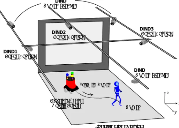
Experiments were performed in the laboratory room, which is about 7 m in both width and depth, is used for the ISpace. The ISpace has a mobile robot as a human- tracking agent, six DINDs which can obtain the situation in the environment, and a projector and a screen which
present suitable information to the human. Each module is connected through the network communication. Three DINDs are used in order to recognize the mobile robot and to generate the control commands. The other three DINDs are used to recognize the position of the human.
DINDs are placed as shown in Fig. 1 [2].
The placement of the three DINDs for human recognition is optimized to expand the viewable area of the cameras [2] so that the head and hands of the human can be recognized over a wide area. On the other hand, the placement of DINDs for the mobile robot has to be decided by trial and error. It is desirable that the DINDs for the mobile robot recognize the whole of the area covered by three DINDs for human recognition in order to achieve the human-tracking system and reliable mobile robot control. Thus, three DINDs are placed so that the area for human recognition is completely covered.
Human walking information is extracted by background subtraction and by detecting the skin color of a face and hands on captured images. In the coordinate system of the ISpace, the axis is parallel to the screen, the axis is perpendicular to it, and the axis follows the right-hand system. Each DIND measures 3-D positions, which are based on this coordinate system using kinematic relationship of consecutive image frames.
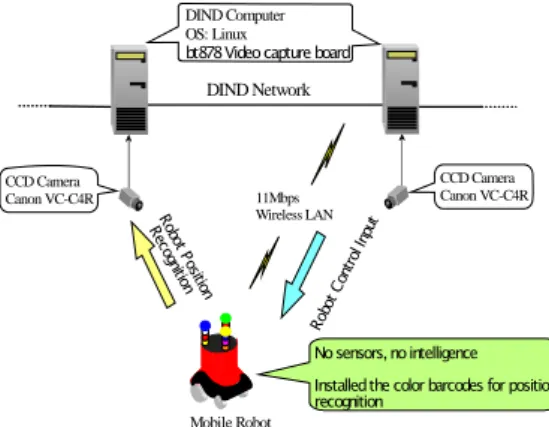
A mobile robot is connected to the DIND network via wireless LAN, as shown in Fig. 2, and shares the resources of the DIND’s. For recognizing the position of the robot, one color panels are installed around the mobile robot. The pattern of the color panel is recognized by the DIND and it estimates the posture and position of the robot by kinematics of robot projected onto an image plane. Since the height of the mobile robot is already known, the position of a mobile robot is reconstructed from one camera image.
DIND
(Human Tracking) (Human Tracking)
DINDHuman Physical Agent
(Mobile Robot)
xy z DIND3
(Robot Control)
Following Human
Intelligent Space
DIND1
(Robot Control)
DIND2
(Robot Control)
Fig. 1. Experimental environment.
Mobile Robot
CCD Camera Canon VC-C4R
DIND Network
11Mbps Wireless LAN
DIND Computer OS: Linux
bt878 Video capture board
CCD Camera Canon VC-C4R
No sensors, no intelligence Installed the color barcodes for position recognition
Robot P osition Recog
nition
Robot Control Input
Fig. 2. Mobile robot and network system in ISpace.
3. Mobile Robot Control for Trajectory Generation
3.1 Tracking control
In order to follow a human, tracking control is performed. Many studies have been performed in the field of the tracking control. However, the trajectory which a mobile robot tracks is limited in most cases to continuous and smooth ones. A human tracking robot should be able to track actual human walking trajectories, including abrupt changes in velocity and direction.
Therefore, stable tracking may not be achieved when conventional tracking control is used. A special control method for the mobile robot to follow humans is required.
In the control of a nonholonomic mobile robot, Brockett’s theorem proved that a smooth state feedback law for an asymptotically stable to one point of the state space does not exist [5]. However, it is necessary to construct a closed-loop control system in which the error between the reference point and the state vector of a mobile robot should become zero for the tracking control of a mobile robot. In recent years, various closed-loop control systems which can overcome the feedback stabilization impossibility of Brockett’s theorem, have been proposed. Reference [5] proposed piecewise- continuous controllers which neglect the ”smoothness”
and [10] proposed tracking control in which a mobile robot follows the trajectory planned as a function of time.
These techniques are very effective in tracking control.
3.2 Kinematics of the camera system and coordinates The camera system in ISpace has the ability of panning and tilting, as shown in Fig. 3. The position and posture of the camera are defined with respect to the base frame.
According to the Denavit-Hartenberg convention, the homogeneous matrix can be obtained after establishing
the coordinate system and representing parameters and an attitude vector of the homogeneous matrix represents Roll( θ
R), Pitch( θ
P) and Yaw( θ
Y) angles by tilting and panning angles of the camera as [10].
To measure the distance from a camera to objects using the camera images, at least two image frames that are captured for the same object at different locations, are necessary. Usually a stereo-camera system has been used to obtain the distance information [6]. However there exist uncertainties in feature point matching and it takes too much time to be implemented in real-time. This approach requires only a frame to measure the distance to the object from the CCD camera. Since the approach becomes possible by assuming that a point-object is located on the floor, there also exist uncertainties in the position estimation. To minimize the uncertainty in the position estimation and to estimate the velocities of the moving object together, a state estimator is designed based on the Kalman filter. The image coordinates for the point object, ( j
, k ), is transformed to the image center coordinates which is orientation invariant in terms of the Roll angle, θ
R, and the size of the image frame, P
xand P
y, ( j′
, k′ ):
⎥ ⎥
⎥ ⎥
⎦
⎤
⎢ ⎢
⎢ ⎢
⎣
⎡
−
−
⎥ ⎦
⎢ ⎤
⎣
⎡ −
⎥ =
⎦
⎢ ⎤
⎣
⎡
2 2 ) cos(
) sin(
) sin(
) cos(
' '
y x
R R
R R
k P j P
k j
θ θ
θ θ
(1)
where P
xand P
yrepresent x and y directional size of the image frame in pixels, respectively.
Network Vision Sensor Vision Sensor
θ
Pθ
ry0 0
(
x y, )
Zccd
ˆ0
r
X Y
θ
rxˆ0
θ
0 0
(
x,
y) r
ˆ0X Y
θ
YImage plane
Fig. 3. Estimation of position information,
r ˆ 0
(upper figure),ˆ 0
θ
(lower one).To estimate the real location, ( x 0 , y 0 ),
θ$ 0 and r$ 0
are estimated using the linear relationship between the real object range within the view angle and the image frame. That is, for a given set of (
θ$ 0 , r$ 0 ), there is one- to-one correspondence between the real object point and the image point. When a point image is captured at ( j ′ , k′ ) on the image center frame, the real object position,
ˆ 0
θ and r ˆ 0 can be estimated as follows, as it is illustrated in Fig. 3:
2 ) cos(
ˆ 0
ry y p ccd
P k r z
θ π − θ + ′
=
(2)
0
'
rx x
j θ
∧= P θ
(3)
where θ
rxand θ
ryrepresent the x and y directional view angles of the CCD camera, respectively. When ( j
, k ) is a image coordinate for the point object, ( j′ , k′ ) is a image coordinate transformed to the image center coordinate. The position of the object with respect to the robot coordinates, (x, y) can be estimated using the θ ˆ 0 and r ˆ 0 [7] as follows:
ˆ ) ˆ cos(
)
ˆ 0 = cos( θ Y + r 0 ⋅ θ Y + θ 0
x (4)
ˆ ) ˆ sin(
)
ˆ 0 = sin( θ Y + r 0 ⋅ θ Y + θ 0
y (5)
where θ
Yrepresents the angle between the mobile robot and the camera of DINDs.
4. Localization and Tracking on the Ground Plane
In the preceding sections, proposed methods have been presented to track and describe people as flat image regions in the 2D image plane. These systems provide the information, where the tracked persons are located in the camera image. However, many applications need to know their location and trajectory in the real 3D scene instead, e.g., to evaluate their behaviour in sensitive areas or to merge the views from multiple camera. Additionally, it has been shown that knowledge about the depth positions
in the scene improves the segmentation of overlapping persons.
A mathematical model of the imaging process is used to transform 3D world coordinates into the image plane and vice versa. To this end, the prior knowledge of extrinsic (camera position, height, tilt angle) and intrinsic camera parameters (focal length, opening angle, potential lense distortions) is necessary. The equations derived in the following use so-called homogeneous coordinates to denote points in the world or image space:
⎟⎟
⎟ ⎟
⎟
⎠
⎞
⎜⎜
⎜ ⎜
⎜
⎝
⎛
= w wz wy wx x
(6) The homogeneous coordinate representation extents the original coordinates ( x , y , z )
by a scaling factor w , resulting in an infinite number of possible descriptions of each 3D point. The concept of homogeneous coordinates is basically a mathematical trick to represent broken- linear transformations by linear matrix operations.
Furthermore, it enables the computer to perform calculations with points lying in infinity ( w = 0 )
. A coordinate transformation with homogenous coordinates had the general form x ~ = Mx
, with M being the transformation matrix:
⎟ ⎟
⎟ ⎟
⎟ ⎟
⎠
⎞
⎜ ⎜
⎜ ⎜
⎜ ⎜
⎝
⎛
= Δ Δ
Δ
s d d d
z r r r
y r r r
x r r r
z y x
1 1 1 1
33 32 31
23 22 21
13 12 11
M
(7)
z α
Z
cc y
y
x
H c 0
D
cX c 0
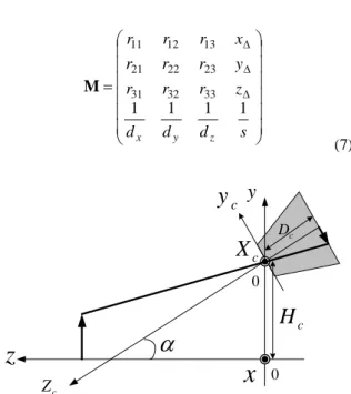
Fig. 4. Elevated and tilted pinhole camera model.
The coefficients r ij
denote the rotation of the coordinate system, ( x Δ , y Δ , z Δ ) the translation,
1 ) 1 , 1 , (
z y
x
d d
d the respective distortion and s the scaling.
Most camera can be approximated by the pinhole model. In case of pincushion or other image distortions caused by the optical system, additional normalization is necessary. The projection of 3D scene coordinates into the image plane of a pinhole camera located in the origin is given by the transformation matrix M H
:
⎟ ⎟
⎟ ⎟
⎟
⎠
⎞
⎜ ⎜
⎜ ⎜
⎜
⎝
⎛
−
=
1 0 0 0
0 1 0 0
0 0 1 0
0 0 0 1
c H
D M
(8)
D c
denotes the focal length of the camera model.
Since the image coordinates are measured in pixel units while other measures are used for the scene positions (e.g.
cm ), measurement conversion is included in the coordinate transformation by expressing D c
in pixel units the width- or height resolution r x
or r y
of the camera image together with the respective opening angles θ x or θ y
:
2 ) tan(
) 2 tan( 2
2 y
y x
x c
r r
D = θ = θ
(9) In a typical set-up, the camera is mounted at a certain height y = H C
above the ground and tilted by an angle α . The according transformation matrices, M R
for the rotation around the x-axis and M T
for the translation in the already rotated coordinate system, are given by:
⎟⎟
⎟ ⎟
⎟
⎠
⎞
⎜⎜
⎜ ⎜
⎜
⎝
⎛
= −
1 0 0 0
0 cos sin 0
0 sin cos 0
0 0 0 1
α α
α α
M
R; ⎟⎟
⎟ ⎟
⎟
⎠
⎞
⎜⎜
⎜ ⎜
⎜
⎝
⎛
= −
1 0 0 0
sin 1 0 0
cos 0 1 0
0 0 0 1
α α
C C
T
H
M H
(10) The total transformation matrix M results from the concatenation of the three transformations:
⎟⎟
⎟⎟
⎟⎟
⎠
⎞
⎜⎜
⎜⎜
⎜⎜
⎝
⎛
−
−
−
= −
=
C C C C
C C R
T H
D H D D
H H
α α αα α
α
α α
α cos sin 0 sin
sin cos
sin 0
cos sin
cos 0
0 0
0 1
M M M M
(11)
the camera coordinates ( x C , y C )
can now by calculated from the world coordinates ( x , y , z )
as follows:
⎟ ⎟
⎟ ⎟
⎟ ⎟
⎠
⎞
⎜ ⎜
⎜ ⎜
⎜ ⎜
⎝
⎛
−
− + +
−
−
=
⎟⎟
⎟ ⎟
⎟
⎠
⎞
⎜⎜
⎜ ⎜
⎜
⎝
⎛
=
⎟⎟
⎟ ⎟
⎟
⎠
⎞
⎜⎜
⎜ ⎜
⎜
⎝
⎛
) sin cos sin 1 (
sin cos
sin
cos cos
1 α α α
α α
α
α α
C C
C C
C C C
C C
C C
H z D y
H z y
H y
x
z M y x
w z w
y w
x w
M
(12)
By dividing the homogenous coordinates by w c , the final equations for the image coordinates are derived:
α
α ( ) sin
cos H y
z D x x
C C
C = − + −
(13) α
α
α α
sin ) ( cos
sin cos ) (
y H z
z y
D H y
C C
C
C + −
−
= −
(14)
The value of z c
is a constant and denotes the image plane, z c = − D c
. The inverse transformation of the image coordinates into the 3D scene requires the prior knowledge of the value in one dimension due to the lower dimensionality of the 2D image. This has to be the height y
above the ground, since the floor position )
, ( x y
is unknown. In the analysis of the camera image, the head and feet coordinates of a person can be detected as the extrema of the silhouette, or, in a more robust way, with the help of body models. Therefore the height is either equal to zero or to the body height H P
of the person. The body height can be calculated, if they- positions of the head y c , H
and of the feet y c , F are detected simultaneously:
) sin cos
)(
cos cos
( , ,
, ,
α α
α
α C C c H
F c
H c F c C
C
P y D D y
y D y
H
H + −
= −
(15)
Besides improved tracking stability especially during
occlusion, tracking on the ground plane also enables the
inclusion of additional real world knowledge into the
system, like the human walking speed limits, minimum distance between two persons or valid ground positions defined by a floor map.
5. Motion Planning for Human Tracking
To follow a walking human, the mobile robot needs to be controlled by considering the relation between the position of the mobile robot and the position of the walking human. Fig. 5 shows the motion planning process of a mobile robot for tracking a walking human.
Each DIND computer system estimates the position of the moving object within m sampling time and selects the shortest distance from its current position to the walking human, assuming the its location is known a priori. The localization scheme of the mobile robot using the information on the walking human, which improves the accuracy in capturing, is developed in [8]. The target point of the mobile robot at k-th sampling time is denoted as $ ( x
Rk + m ) , which is one of the estimated points of the mobile robot after m sampling time.
$ $ $
1~
( ) min ( ) ( )
R opt O R
m M
x k m x k m x k m
+ =
=
+ − +(16)
where $ ( x
Rk + m ) is the position of the mobile robot after m sampling time, and the mobile robot moves along the shortest path towards the target point $ ( x
Ok + m ) .
The position of the moving objects in the cartesian coordinate system is acquired using the relation between image frames. The linear and angular velocities of the moving objects are estimated by the state estimator, Kalman filter. After estimating the trajectory of the moving objects, the optimal trajectory and motion
Human-Following Robot
$ ( )
Rx k
$ ( )
Rx k
$ (
R2)
x k+
$ (
R3) x k +
$ (
R4)
x k+
$ (
R)
x k+
M$ (
O) x k + M
$ (
O4) x k +
$ (
O3) x k + $ ( x k
O+ 2)
$ ( 1)
Ox k +
$ ( )
Ox k
Walking Human
Fig. 5. Estimation of the trajectory for Human-tracking.
Control command Image
DATA
(1) Estimate human position of object from
Image data of DIND
(1)
Estimate human position of object fromImage data of DIND
(2) Optimal State observer (Kalman Filter)
(2) Optimal State observer (Kalman Filter) object (x,y)
k k
y x ,
(3) Estimate function of and Predict
object trajectory (3) Estimate function of and Predict
object trajectory (4)
Decision optimal object target and Control mobile robot
(4) Decision optimal object target and Control mobile robot
ω , v
State of object
Object trajectory
ˆ ˆ
k m k m
x y
+ +
ω ,
Human-Following in ISpace
v t
camera n+1 camera n
t
Fig. 6. Mobile robot control for estimating and tracking.
planning of the mobile robot are decided in order to follow the walking human in the shortest time. The tracking figure shows the overall structure of mobile robot control for human tracking.
6. Experiments
Experiment was performed to show the estimating and tracking a waling human. Fig. 7 shows the experimental results for estimating and tracking a walking human.
Mobile robot is attached with 70x20[cm] red-colored panels. Human walks random velocities in the range of 45-50[cm/sec]. First, mobile robot detects the moving human using cameras in ISpace. When a walking human is detected within view, mobile robot tracks it tracking the proposed method. And Fig. 7 illustrates that the mobile robot tracking a human in the shortest time path as temporary position in experiments. The minimum path was estimated using the trajectories of the mobile robot and the human, while the mobile was tracking the walking human.
(a) (b)
Fig. 7. Experimental results for Human-tracking.7. Conclusion
This paper proposes a method of human-tracking for
mobile robot to track and follow a walking human in
ISpace environment. First, a control algorithm using a
position estimation of moving objects, walking human
and mobile robot, based on the kinematic relationship of
consecutive image frames was proposed for a mobile
robot in order to follow a walking human whose position is estimated incompletely. The proposed model is able to absorb the gap between the motion of the human and the mobile robot. It was shown that movement estimation of the objects using a Kalman filter based DINDs for tracking and motion planning of a mobile robot to follow the walking human, based on its estimated trajectory, within the shortest time.
Acknowledgments