기호설명
R 열저항
Heat sink 바닥면 최대 온도
유입되는 유체의 온도
유체 평균온도
휜의 열저항
유동에 의한 열저항q
발열량PP
펌핑파워Q
유량
압력강하h
열전달계수s
휜과 벽면간 거리H
휜의 높이1. 서 론
최근 전자 및 기계 산업의 발전으로 인하여 전 자장비는 점차 고성능화 소형화되고 있다 그 결, . 과 전자장비의 단위면적당 발열량은 증가하고 있 으며 전자제품 내부를 적정 온도로 유지하기 위 한 냉각 기술이 중요한 문제로 대두되고 있다.
고발열 전자장비를 효과적으로 냉각하기 위한 방법중 하나로 1981년 Tuckerman과 Pease는 를 제안하였다 그 후 많은 microchannel heat sink .
연구자들은 Tuckerman과 Pease가 제시한 모델을 개선하며 각 상황에서 최적화된 heat sink를 제시 하였다.
팁 클리어런스가 스트레이트 휜 히트싱크의 냉각성능에 미치는 영향에 관한 실험적 연구
김진욱
†
․김성진*
․민정임**
․이승규***
Experimental Study on the Effect of Tip Clearance for a Straight Fin Heat Sink
Jin Wook Kim, Sung Jin Kim, Jung Im Min, Seung Gyu Lee
Key Words:
Tip clearance(팁 클리어런스), heat transfer(열전달), straight fin heat sink(스트레이트 휜 히트 싱크), thermal resistance(열저항), cooling performance(냉각성능).Abstract
In this paper, the effect of tip clearance on the cooling performance of the microchannel heat sink is presented under the fixed pumping power condition. For the various types of microchannel heat sink having different size of fin width and channel width, experimental study is conducted. Through the experiment, the tip clearance effect is investigated by increasing tip clearance from zero. As a result, it is shown that cooling performance of heat sink with tip clearance is better than that of heat sink without tip clearance. For the microchannel heat sink with tip clearance, the optimum conditions for cooling performance is also studied.
†LG전자 Digital Display 연구소 E-mail : [email protected]
TEL : (02)526-4191 FAX : (02)572-3086
* KAIST 기계공학과
** KAIST 기계공학과 대학원
*** LG전자 Digital Display 연구소
는 의 윗면이 와 H. Shaukatullah[9] heat sink duct 맞닿지 않은 환경에서 heat sink의 열성능을 평가 하였다 이 때 대부분의 유동은 상대적으로 유동. 저항이 작은 bypass부분으로 흘러가 heat sink중 가장 온도가 높은 바닥면을 효과적으로 냉각할 수 없었다 그러나. heat sink의 윗면이 duct와 맞닿 은 환경에 장착된 heat sink는 모든 유체가 fin사 이로 흘러 fin을 효과적으로 냉각시킬 수 있음을 제시하였다.
Lau[7], El-Sayed et al.[6], O. N. Sara[4, 5]등은
의 끝이 의 내벽과 접한 상태 즉
fin duct , tip
의 변화에 따른 의 열성능을 연
clearance heat sink
구하였다 실험은. tip clearance가 channel의 폭보다 큰 영역에서 이루어졌고 그 결과 tip clearance가 냉각성능에 나쁜 영향을 준다고 발표하였다 또한. 이들의 연구는 tip clearance가 channel 폭보다 큰
의 에 치중하였다 따라서
macro size heat sink .
에서 작은 가 존
microchannel heat sink tip clearance 재할 경우의 열성능에 관한 실험적 연구는 아직 이루어지지 않은 실정이다.
은 제약조건이
Min et al.[3] constant pumping
이며 를 갖는 에 관
power high aspect ratio heat sink 한 수치해석을 수행하였다 이들은 기존의 연구자. 와는 달리 tip clearance가 channel의 폭보다 작을 때 열성능을 평가하였다. Constant pumping power 조건에서 작은 tip clearance가 존재하면 유체의 압 력강하는 감소한다 그러나. heat sink를 통과하는 유량은 증가하기 때문에 heat sink의 냉각성능이 향상됨을 보여주었다.
소형화된 전자제품에서는 heat sink를 장착할 수 있는 공간의 제약이 심해져 heat sink가 장착되었 을 때 tip clearance가 전자제품의 냉각성능에 미치 는 영향을 연구하는 것은 중요하다 따라서 본. , 연구에서는 constant pumping power의 제약조건으 로 실험함으로써 tip clearance가 microchannel heat 의 냉각성능에 미치는 영향을 알아보고 실제 sink
적용가능성을 제시하고자 한다.
Fig.1 Definition of tip clearance
문제정의 및 실험장치 2.
2.1 문제정의
본 연구에서 다루는 microchannel heat sink의 형 상 및 경계조건을 Fig.2에 나타내었다. Heat sink 의 윗면과 측면은 단열되었으며 열은, heat sink의 바닥면으로부터 x축방향으로 heat sink를 통과하는 유체에 의해 외부로 방출된다.
Fig.2 Problem description
본 연구에서는 heat sink의 열성능을 평가하기 위하여 다음과 같이 열저항을 정의하여 사용한다.
(1)의 열성능을 평가하기 위한 제약조건 Heat sink
은 constant pumping power이며 다음과 같이 표현 할 수 있다.
PP=Q☓ΔP (2)
2.2.1 실험장치
본 연구에서는 세 가지의 heat sink를 제작하여 수행하였다 각. heat sink의 크기는 Table.1 과 같 다.
은 실험장치의 개략도 및 사진이다 본 실
Fig.3 .
험의 작동유체는 공기이며 test section으로 유입되 는 유량을 측정하고자 Brooks사의 MFC를 사용하 였다. Heat sink의 앞단과 뒷단에서 발생하는 압력 강하를 측정하기 위하여 Fig.4와 같이 11개의
을 부착하였다 상단에 위치
pressure tap . Heat sink
한 10개의 pressure tap중 원하는 한 지점과 뒷단 에서의 압력차를 측정하기 위하여 solenoid valve
를 사용하였다
switch .
본 연구에서는 열손실을 최소화하고자 Heat
의 네 측면을 모두 로
sink base plate silicone rubber s
H
Side wall (Insulated)
Side wall (Insulated) Cover plate
(Insulated)
Thin film heater (Uniform heat flux)
z
y x
감쌌으며 heat sink의 아래부분에 spacer를 이용하 여 공기층을 만들었다. Test section의 외벽에 단열 재인 urethane foam과 styrofoam을 부착함으로써 로부터 주변으로 유출되는 열손실을 최소 heat sink
화하였다. Heat sink바닥면과 heater사이, heat sink 의 네 측면에 heat flux sensor를 부착함으로써 로부터 외부로 방출되는 열손실을 정확하 heat sink
게 예측하였다.
의 열저항을 구하기 위하여
Heat sink heat sink
로 유입되는 공기온도와 heat sink바닥면의 온도를 측정하였다 그리고. heat sink의 바닥면에 4.5mm 의 간격으로 6개의 구멍을 가공하고 thermocouple 을 부착하였다.
Table.1 Size of heat sinks
Fig. 3 Experimental apparatus
Fig. 4 Pressure tap
Fig.5 Test section
3. 실험결과
온도장 검증 3.1
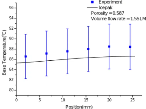
본 연구에서는 실험을 통해 측정된 결과를 을 이용한 수치해석결과와 비교하였다 측
Icepak .
정된 온도와 Icepak을 통해 예측한 값을 비교하여
에 나타내었다 을 이용하여 해석한
Fig. 6 . Icepak
결과 porosity가 0.59인 heat sink에 0.5SLM, 1SLM 의 유량이 흐를 경우 실험 결과와 5%이내의 error 를 보였다.
0 5 10 15 20 25
80 82 84 86 88 90 92 94 96
Experiment Icepak Porosity = 0.587 Volume flow rate = 1.5SLM
B a s e Tem per at ure(
oC)
Position(mm)
Fig. 6 Temperature of heat sink base plate
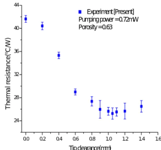
를 변화하며 측정한 열저항을
Tip clearance Fig.
에 나타내었다 실험결과에 따르 7, Fig. 8, Fig. 9 .
면 tip clearance가 증가함에 따라 열저항은 감소하 며 일정한 tip clearance이후 열저항은 다시 증가함 을 확인할 수 있다. Porosity가 0.47, 0.59인 heat
의 경우 가 일 때 가
sink tip clearance 1mm , porosity
인 의 경우 일 때 냉각성능이
0.63 heat sink 1.05mm
Porosity 0.47 0.59 0.63
Fin height(mm) 1.5 1.5 1.5
Base thickness(mm) 2 2 2
Fin thickness( μ m) 541 420 378
Channel width( μ m) 459 580 622
Base length(mm) 25.5 25.5 25.5
Base width(mm) 25.5 25.5 25.5
Flow
Solenoid valve MFC
Air
Pressure transducer
Test section
Heater Thermocouple MFC
Controller
Honeycomb Power supply
PC
Data acquisition /Switch unit
조절장치 Tip clearance
Heat sink
4mm 4mm
6mm 21mm
Flow
45.5mm 20mm 35.5mm 100mm
25.5mm
가장 우수하다 이러한 경향성은. porosity의 변화 에 관계없이 tip clearance가 존재한 heat sink의 냉 각성능이 tip clearance가 없는 heat sink의 냉각성 능보다 우수함을 의미한다. 즉 냉각성능은 tip
가 존재함에 따라 가 존재하
clearance tip clearance
지 않는 heat sink보다 최대 40% 이상 향상된다. 이상의 현상은 다음과 같이 설명할 수 있다.
의 증가에 따른 열저항이 감소하는 Tip clearance
경향은 첫째, Tip clearance가 존재함에 따라 fin의 끝에서 유체로 열이 전달될 수 있기 때문에 열전 달이 촉진된다.
둘째, constant pumping power의 제약 조건에서
가 증가함에 따라 를 통과하
tip clearance heat sink
는 유체의 압력강하는 줄어들고 유량은 증가한다.
이 때 heat sink로 유입되는 유체중 일부는 fin 사 이로 흐르지 않고 fin의 윗부분으로 흐르게 된다. 따라서 fin의 끝 주변에서 열전달 성능은 향상되 는 반면 바닥면 부근의 열전달 성능은 악화된다.
따라서 heat sink바닥면을 식힐 수 있는 최소한의 유체가 유입될 때까지tip clearance가 증가해도
의 냉각성능은 향상된다 하지만
heat sink . tip
가 최적값 이상 커지면 대부분의 유체는 clearance
윗공간으로 흘러 heat sink의 냉각성능은 악화된 다.
에서 볼 수 있듯 가 에
Fig. 10 tip clearance 0mm 서 0.4mm까지
R fin
은 거의 변화가 없다 이 구간. 에서는 tip clearance가 존재함에 따라 fin의 끝이 새로운 열전달 면적으로 확보되어 열전달이 촉진 된다 그리고 유체가. fin 사이영역을 이탈함에 따 라 열전달 성능이 악화되는데 두 경향성이 비슷 하기 때문에R fin
의 변화는 거의 없다 그러나.가 이상이 되면 사이를 흐르
tip clearance 0.4mm fin
는 유량은 점차 감소하여 fin근처에서의 h는 더욱 감소한다 따라서 이 영역에서.
R fin
은 증가하는경향을 볼 수 있다.
R flow
는R fin
과 반대의 경향을 보인다. Tip 가 증가함에 따라 압력강하의 감소분만큼 clearance증가한 유량 때문에 뜨거운 heat sink에서 전달된 열을 방출할 수 있는 유체의 수송능력이 증가한 다 따라서. heat sink를 통과하기 전과 후에서 측 정한 유체의 온도차는 감소하며
R flow
는 감소한다.
Fig. 7 The effect of tip clearance on the cooling performance of heat sink when porosity is 0.47
Fig. 8 The effect of tip clearance on the cooling performance of heat sink when porosity is 0.59
Fig. 9 The effect of tip clearance on the cooling performance of heat sink when porosity is 0.63
0.0 0.2 0.4 0.6 0.8 1.0 1.2 1.4 1.6
25 30 35 40 45 50 55
60 Experiment
Pumping power = 0.92mW
T h e rm a l re si sta n ce (
oC/ W )
Tip clearance(mm)
0.0 0.2 0.4 0.6 0.8 1.0 1.2 1.4 1.6
24 28 32 36 40
Experiment [Present]
Pumping power = 0.92mW Porosity = 0.59
T hermal res is tance(
oC/ W )
Tip clearance(mm)
0.0 0.2 0.4 0.6 0.8 1.0 1.2 1.4 1.6
24 28 32 36 40 44
Experiment [Present]
Pumping power = 0.72mW Porosity = 0.63
T h e rm a l resi stan ce (
oC/ W )
Tip clearance(mm)
Fig. 10 Thermal resistance of heat sink
를 갖는 의 적용
4. Tip clearance heat sink 가능성
4.1 Channel폭의 변화에 따른 heat sink 냉각성 능 비교
Channel폭이 heat sink의 냉각성능에 미치는 영 향을 확인하고자 channel 폭이 다른 세 가지 heat sink의 실험결과를 비교한다. Channel폭의 변화에 따른 실험결과는 Fig 11과 같다. Channel폭이 증 가함에 따라 fin사이를 흐르는 유체의 유동저항은 감소한다. 따라서 동일한 tip clearance가 존재할 때 channel폭이 증가함에 따라 fin사이를 통과하는 유량은 증가한다. 따라서 tip clearance가 더 증가 할 때까지 유체는 바닥면 주변으로 충분히 흐르 기 때문에 channel 폭이 작은 heat sink보다 큰 지 점에서 tip clearance의 최적값이 존재한다
4.2 Pumping power의 변화에 따른 heat sink 냉 각성능 비교
Pumping power의 변화에 따른 heat sink의 냉각 성능을 Fig 12에서 비교하였다. Porosity는 0.63이 며 0.72mW와 0.92mW의 pumping power에서 측정 한 열저항을 나타냈다.
그림에서 알 수 있듯 pumping power가 증가함 에 따라 냉각성능은 향상되지만 tip clearance의 최 적값은 감소한다. 동일한 heat sink에서 pumping power의 증가는 heat sink를 통과하는 유량이 증가 함을 의미한다. 따라서 heat sink에서 전달된 열을 수송할 수 있는 능력이 커져 냉각성능이 향상된
다.
동일한 tip clearance가 존재할 때 pumping power가 증가할수록 fin사이에서의 유동저항도 커 진다. 따라서 fin사이를 흐르는 유량은 감소한다.
그러나 작은 pumping power로 유체가 유입될 경 우 fin사이의 유동저항이 더 증가할 때까지 fin사
이로 유체는 충분히 흐를 수 있다. 따라서
pumping power가 감소함에 따라 tip clearance의 최적값은 증가한다
Fig.11 Cooling performance varying s/Wc
Fig.12 Cooling performance varying pumping power
5. 결론
본 연구에서는 constant pumping power 의 제약 조건에서 microchannel heat sink의 열성능에 중요 한 영향을 주는 인자인 fin의 두께, channel간격, 를 변화시키며 실험을 수행하였다 실
tip clearance .
험을 통하여 tip clearance는 microchannel heat sink 의 냉각성능을 향상시킴을 확인하였다.
제약조건이 constant pumping power일 때 tip
0.0 0.2 0.4 0.6 0.8 1.0 1.2 1.4 1.6
5 10 15 20 25 30 35
40 R
flowR
finPumping power = 1.55mW Porosity = 0.47
T herm al re sistan ce(
oC/W )
Tip clearance(mm)
0.0 0.5 1.0 1.5 2.0 2.5
20 25 30 35 40 45 50 55
60 Porosity = 0.47
Porosity = 0.59 Porosity = 0.63 Pumping power = 0.92mW
T h er m a l r e si sta n c e (
oC/ W )
s/Wc
0.0 0.5 1.0 1.5 2.0 2.5
20 25 30 35 40
45 Pumping power = 0.72mW
Pumping power = 0.92mW Porosity = 0.63
Therm a l resis tance (
oC/W )
s/Wc
가 증가함에 따라 압력강하는 감소하며
clearance ,
를 통과하는 유량은 증가하기 때문에 heat sink
의 냉각성능은 향상된다 그러나
heat sink . tip
가 과도하게 커지면 의 윗 공간으로
clearance fin
많은 유체가 지나가므로 heat sink를 효과적으로 냉각시킬 수 없어 냉각성능은 악화된다 따라서.
가 최적화된 의 냉각성능은
tip clearance heat sink
가 존재하지 않는 에 비하여
tip clearance heat sink 향상됨을 예측할 수 있다.
연구결과 tip clearance가 존재하는 microchannel
는 의 형상과 에 관
heat sink heat sink pumping power 계없이 tip clearance가 존재하지 않는 heat sink보
다 냉각성능이 향상됨을 확인하였다. Tip
의 최적값은 의 형상과 작동환경
clearance heat sink
에 따라 달라진다. Pumping power가 작을수록,
폭이 클수록 의 최적값은 증가
channel tip clearance 한다.
이상의 연구결과를 바탕으로 향후 전자제품 냉 각용 heat sink를 설계할 때 적절한 tip clearance를 제공하면 냉각성능을 향상시킬 수 있을 것으로 예상된다.
참고문헌
(1) Ho Chul Ryu, 2001, "Compact modeling of a pin fin heat sink through experiment investigation", Master thesis, pp. 5-8.
(2) Kim, Duckjong, 2003, "Analysis of heat and fluid flow in microstructures for high power dissipation using a porous medium approach", Doctoral dissertation, pp. 13-19.
(3) Jung Yim Min, Seok Pil Jang, Sung Jin Kim, 2004, "Effect of Tip clearance on the cooling performance of a microchannel heat sink", Int. J.
Heat and Mass Transfer. pp. 1099-1103.
(4) O. N. Sara, 2003, "Performance analysis of rectangular ducts with staggered square pin fins", Energy Conversion and Management, Vol. 44, pp.
1787-1803.
(5) O. N. Sara, S. Yapici, M. Yilmaz, 2001,
"Second law analysis of rectangular channels with square pin-fins", Int. Comm. Heat Mass Transfer, Vol. 28, No.5, pp. 617-630.
(6) Saad A. El-Sayed, Shamloul M. Mohamed,
Ahmed M. Abdel-latif, Abdel-hamid E. Abouda, 2002, "Investigation of turbulent heat transfer and fluid flow in longitudinal rectangular-fin arrays of different geometries and shrouded fin array", Experimental Thermal and Fluid Science, Vol.26, pp. 879-900.
(7) KEI S. Lau and Roop L. Mahajan, 1989,
"Effects of tip clearance and fin density on the performance of heat sinks for VLSI packages", IEEE Transaction on Components, Hybrids, and Manufacturing Technology, Vol. 12, No. 4, pp.
757-765.
(8) E. M. Sparrow, D. S. Kadle, 1986, "Effect of Tip-to-shroud clearance on turbulent heat transfer from a shrouded, longitudinal fin array", Journal of Heat Transfer, Vol. 108, pp. 519-524.
(9) H. Shaukatullah, Wayne R. Storr, Bernt J.
Hansen, Michael A. Gaynes. 1996, 12th IEEE Semi-Therm Symposium, "Design and optimization of pin fin heat sinks for low velocity applications", pp. 151-163.
(10) D. B. tuckerman and R. F. W. Pease, 1981,
"High performance heat sinking for VLSI", IEEE Electron Device Letters, Vol. EDL-2, No.5, pp.
126-129.
(11) S. J. Kim, D. Kim, 1999, "Forced convection in microstructures for electronic equipment cooling", Journal of Heat Transfer, Vol. 121, pp.
639-645.
(12) Incropera, F. P., and DeWitt, D. P., 1996, Fundamentals of Heat and Mass Transfer, 4th ed., John Wiley & Sons, Inc., New York
(13) Blevins, 1992, Applied fluid dynamics handbook, Krieger.
(14) Bejan, 1995, Convective heat transfer, Willey