A STUDY ON HEAT TRANSFER THROUGH THE FIN-WICK STRUCTURE
MOUNTED IN THE EVAPORATOR FOR A PLATE LOOP HEAT PIPE SYSTEM
Xuan Hung Nguyen
*, Byung-ho Sung
*, Jeehoon Choi
*,**, Junghyung Yoo
**,
Minwhan Seo
**and Chulju Kim
†Key Words :
Loop Heat Pipe, fin-wick structure, and electronic cooling device
Abstract
This paper investigates the plate loop heat pipe system with an evaporator mounted with fin-wick structure to dissipate effectively the heat generated by the electronic components. The heat transfer formulation is modeled and predicted through thermal resistance analysis of the fin-wick structure in the evaporator. The experimental approach measures the thermal resistances and the operating characteristics. These results gathered in this investigation have been used to the objective of the information to improve the LHP system design so as to apply as the future cooling devices of the electronic components.
Nomenclature hfg : latent heat of vaporization, [J/kg]
h: heat transfer coefficient [W/m2K] Q : heat load, [W]
R : thermal resistance, [℃/W] T : temperature, [℃, K] A: area [m2]
L : length [m]
Se : evaporator heat transfer area [m2]
Greek Symbols h : overall surface coefficient
Subscripts ∞ : ambient eff: effective j: junction sat : saturation t: total f : fin : subcooling
Introduction
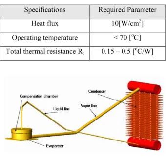
The performance of electronic components has been increasing, resulting in the problem of increased operating power and temperature. The stability and performance of electronic components will decrease given that the operating temperature is going on too higher. Thus, it is necessary to design cooling devices so as to dissipate effectively heat generated by electronic components. And then the specification of the cooling device against CPUs released recently is given in Table 1.
The total thermal resistance, that is used to evaluate the thermal performance of the cooling device, is required to achieve from 0.5 to 0.15oC/W in order to meet the demand of the specification. For the lowest total thermal resistance, there are so many techniques such as a heat sink with a fan, embedded heat pipes and so on.
The loop heat pipe(LHP) system, a two phase capillary pumped heat device, is suggested as a candidate cooling device to manage thermal problems. As opposed to a conventional heat pipe which has wick structure throughout its container, the wick structure in the LHP
†
Corresponding Author,School of Mechanical Engineering Sungkyunkwan University
E-mail : [email protected]
TEL : (031)290-7434 FAX : (031)290-7434
*
School of Mechanical Engineering Sungkyunkwan University**
R&D Center, Zalman Tech Co., Ltd.Table 1 Required parameters for CPUs Specifications Required Parameter
Heat flux 10[W/cm2]
Operating temperature < 70 [oC] Total thermal resistance Rt 0.15 – 0.5 [oC/W]
Fig. 1 Schematic of Loop heat pipe system
system is mounted in only the evaporator section. Besides vapor and liquid flow is in the same direction.
Furthermore, many remarkable features like high heat transfer capability, robust operation, and working in any gravity fields, LHP is evaluated as a promise device applied in electronic cooling techniques.
Typically, the LHP as shown in Fig. 1, consists of an evaporator, a compensation chamber, vapor and liquid lines and a condenser. In order to meet the parameters of the LHP system design for the CPU cooling with needs of high heat dissipation and lowest total thermal resistance, many ideas have been suggested for the wick structure design. Many researches have been performing and reporting with its thermal analysis, and experimental results. The figure 2 shows the flat-plate-type LHP evaporator. The evaporator is a circular configuration with the wick structure, vapor removal channels, a compensation chamber, and an outer casing. Vapor removal channels in the contact zone of the evaporator can be located in wick body directly or in the bottom of the evaporator body. The vapor removal channel shape effects on total pressure drop of the system. The contact
Fig. 2 Flate-plate- type evaporator
zone effects on heat transfer coefficient, and heat transfer capacity as well as the total thermal resistance. Randeep Singh, and et al. have reported the flat-circular-disk LHP evaporator with the vapor removal channels were made in the bottom of the evaporator directly. Copper was selected as the material of the evaporator with sintered nickel wick. Then the thermal resistance of the evaporator achieved as low as 0.06oC/W with the total thermal resistance 1.2oC/W while the maximum value for heat transfer coefficient in the evaporator reaches to 22600W/m2oC. [3] On the other hand, the total thermal resistance of another LHP which has the vapor removal channels made in the plane of the sintered titan wick can reach to 1.45K/W. [5]
Beside the ideas for improving the evaporator, appropriate selection of working fluid is also considered to reduce the total thermal resistance of the LHP system. Generally, the working fluid has been using instance water, acetone, ammonia, and pentane. Water has high latent heat along with the surface tension that is satisfied with high heat flux and gravity height. Oppositely pentane is proper with low heat transfer rate and in small pressure drop because of its low latent heat and surface tension.
In this study, with the desire of reducing the thermal resistance of the evaporator, the fin-wick structure was designed and applied to the LHP system. This structure points out figure 3. The vapor removal channels are
incorporated between fins and a secondary wick. The secondary wick which supplies liquid to primary wicks plays a role in place of the compensation chamber of the normal LHP system. This paper describes not only the thermal analysis of the evaporator but also results from experiments on the LHP with the fin-wick structure.
1. Thermal Analysis of the LHP
It is important to design the LHP based on the characterization and optimization of heat transfer at the contact zone between a heated surface and a porous structure. Unlike previous design, in order to enhance heat transfer coefficient, the fin structure is located in this zone. The objective of the fin structure of the rectangular shape as shown in Fig.3 is to obtain vapor removal channels and to reduce the contact thermal resistance. As shown in Fig.3, heat is applied through the bottom of evaporator to vaporize the working fluid in vapor channels. The porous structure that consisted of primary wick and secondary wick circulates liquid from condenser by means of pumping its capillary pressure.
The primary wick should be required higher thermal conductivity and capillary pressure than the secondary wick. Due to the increase of the contact area between the heated surface and the porous structure, the contact conductance coefficient will be reduced as well as decreasing the evaporator resistance. This mechanism will be discussed in next stages of this paper.
Figure 3 shows the thermal diagram of this evaporator. In this analysis, it is assumed that heat removes from evaporator to surrounding ambient is negligible. Heat applied from the heat source used mainly to vaporize liquid. A little amount of heat is leaked through the secondary wick makes increasing temperature of liquid returning from condenser. The main mechanism in this zone is boiling process of working fluid. Almost of heat conducted through the bottom plate of evaporator is sup-
Fig.3 The evaporator with the fin-wick structure
Fig.4 Thermal diagram of the primary wick
plied to vaporize working fluid. In this case, boiling heat transfer coefficient can be calculated by Mostinski’s equation[6]:
)
(
106
.
0
P
c0.69q
0.7f
P
Rh
=
´
´
¢¢
´
(1)where,
h
the is the pool boiling heat transfer coefficient (W/m2K),q ¢¢
is the heat flux (W/m2), PC isthe critical pressure (bar),
f
(
P
R)
is a function of the reduced pressureP
R=
P
/
P
C, and)
10
4
8
.
1
(
)
(
P
RP
R0.17P
R1.2P
R10f
=
+
+
(2)The heat transfer mechanism in the interface zone includes not only the heat conductance through the
bottom of the evaporator but also the heat convection performed by each fin together with the heat transfer coefficient
h
of the vapor flow. Thus, the evaporator thermal resistance can be calculated as follow:t v j
hA
kA
L
R
0 11
h
+
=
- (3)where, h0 is overall surface coefficient, [8]
ú û ù ê ë é -= 1 (1 ) 0 f t f A A h h (4)
As assumed above, the heat input can be divided into two parts as below equation:
6
0
Q
Q
Q
=
hfg+
(5)hfg
Q
is the latent heatfg
hfg
m
h
Q
=
&
(6)6
Q
is the heat leaked through the secondary wick)
(
66
m
C
plT
T
scQ
= &
-
(7)
The subcooling process is the important factor to undertake the LHP successfully. The temperature of the liquid inlet is affected by the heat transferred through the secondary wick as well as both conduction and convection by liquid flow from subcooler.[7]
The temperature difference between vapor and the liquid inlet can be calculated as under mentioned.
e eff e eff sc sat p sat
S
k
L
Q
S
k
L
T
T
C
m
T
T
4 6 4 62
)
(
+
-=
-
&
(8) In which,÷
÷
ø
ö
ç
ç
è
æ
-+
+
-+
=
)
/
1
(
/
2
)
/
2
(
2
/
2
s l s l s l s l s effk
k
k
k
k
k
k
k
k
k
j
j
(9)where, ks is the thermal conductivity of the secondary
wick, kl is the thermal conductivity of working fluid.
Total thermal resistance of the LHP is determined through temperature difference between junction temperature and ambient air temperature in accordance with the heat input.
0
Q
T
T
R
t j ¥-=
(10)2. Experiments of the LHP
The LHP for this experiment is shown in Fig.5. For the evaporator as mentioned above, the rectangular fin shapes (45x40mm, thickness 20mm) were fabricated from aluminum. The primary wicks were sintered with stainless steel particles while stainless steel fibers were sintered for the secondary wick. For connecting between evaporator and condenser, both vapor and liquid lines were 6.5mm of out diameter and 4.5mm of inner diameter. A louver-fin radiator is set up to condense the vapor transported from evaporator and then the fan is used together. The n-pentane is selected as the working fluid for this LHP. The bottom of the evaporation employs a foil heater connecting with the power supply to simulate CPU power. Then the heater applied the heat load
Q
0 from 10W to 100W to the bottom of the evap-Fig.5 LHP with fin – structure evaporator
orator which insulated but the upper of the evaporator is exposed to the ambient air. Thermocouples(T-type) are attached to each point to measure temperature and the data recorder(DR230) of Yokogawa Co. Ltd was monitored.
3. Results and discussion
One dimension heat transfer assumption was applied to analyze the thermal mechanism for this evaporator. As heat was added in active zone, the interface area temperature was raised up and resulted in vaporization of the working fluid that evaporated between vapor channels and vapor lines. The complicated heat transfer mechanisms occurred within this process, however, the heat conduction and the heat convection mechanism with boiling heat transfer coefficient in the fin structures were analyzed to simulate the thermal diagram as mentioned above. The evaporator is the most important component of the LHP and depends on the overall performance of this device. The efficiency of the heat transfer process in the evaporator zone of the LHP is measured on the basis of the evaporator thermal resistance which is the resistance presented to the heat flow from the evaporator active zone to the vapor inside the evaporator zone and in this case, it is determined on the base of fin effects as well as thermal conductivity with some given parameters. Figure 6 shows the evaporator thermal resistance versus
Fig.6: Evaporator thermal resistance vs. heat input
Fig.7: Evaporator thermal resistance vs. length of fins
heat input that is in range from 10W to 100W. While the evaporator thermal resistance in calculated results are from 0.091[oC/W] to 0.038[oC/W], experimental results are from 0.089[oC/W] to 0.034[oC/W]. As of these results, the error rate is about 5%. Thus the assumptions of thermal analysis are acceptable. Furthermore, the very low values of Rj-v obtained in this LHP evaporator, with
the maximum value of 0.038[oC/W] at 100W, proved significant effect of the fin structures on this evaporator.
Additionally, from the investigation into influence on the evaporator thermal resistance of the fin structures, the calculated evaporator thermal resistance relying on length of fins was suggested. As shown in Fig. 7, these calculated results demonstrated rising evaporator thermal resistance in accordance with increasing length of fins due to decrease of overall surface coefficient.
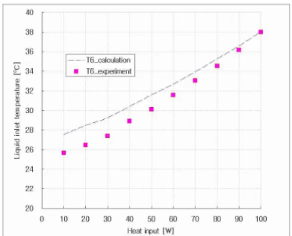
Fig. 8 Liquid inlet temperature versus heat input
Fig.9 The total thermal resistance versus heat input
Fig.10 The total thermal resistance versus length of fin
For instance, when the heat load 100W was applied, Rj-v
given the length 0.002m of fins is 0.019 oC/W as long as Rj-v of 0.008m is 0.034oC/W. These results pointed out
that the length of fins needs to be evaluated prior to the contact zone design of the evaporator.
Fig. 10 Operation temperature of the LHP according to the heat loads
Figure 8 illustrates the liquid inlet temperature at the evaporator. The liquid inlet is adjacent to the secondary wick which plays roles to restrain the thermal resistance by means of the heat leaked from vapor channels. The liquid inlet temperature is proportional to heat loads in experimental results. By the way, the calculated results are smaller than these one. It seems to be this difference because of ignoring the heat not only transferred the housing wall of the evaporator but also dissipated to the ambient air.
In this thermal analysis, the total thermal resistance from heat source to the ambient air was determined to evaluate the fin structure effects regarding to the LHP performance. Figure 9 describes total thermal resistance in calculation and experiments versus heat loads. Because the evaporator is fabricated from aluminum with the low thermal conductivity of sintered stainless steel wicks and n-pentane with low latent heat per liquid specific heat, the total thermal resistance of the LHP is very low. On the other hand, the results shown in Fig. 10 provided another explanation about the total thermal resistance with the influence of the fin geometry. As shown in Fig.9, with 0.57oC/W of the total thermal resistance at 10W and 0.2oC/W at 100W, the total thermal resistance values of the LHP were satisfied with the requirements in electronic cooling devices. In addition, as of the operating temperature of the LHP as shown in Fig. 11, there is no oscillation phenomenon. The maximum junction temperature is blower than 45oC when the heat load 100W was applied.
4. Conclusion
With regard of the thermal analysis of a plate LHP system mounted with the evaporator with fin-wick structures, the error rate between calculated and experimental results is about 10%. This thermal analysis may be able to be used to determining and predicting some parameters and operating characteristics for the evaporator with fin- wick structures
In experimental results, the range of the evaporator thermal resistance was from 0.089 oC/W to 0.034 oC/W. These results proved the clear effects of fin-wick structures to rise the evaporator performance. Thus, the structure can enhance heat transfer capacity in active zone in evaporator comparing with previous designs reported. Especially, the change of this design reduced the total thermal resistance of the LHP system with the range in 0.2[oC/W] to 0.57[oC/W] while the junction temperature is smaller than 45oC. Therefore, this LHP system can meet the requirements of electronic cooling devices.
Acknowledgement
This study was supported by the Ministry of Knowledge Economy, Republic of Korea.
Reference
(1) A. Bar, Cohen, 2000, “Computer-related thermal packaging at the millenial divide,” Electronic cooling Magazine, Vol. 6, No.1.
(2) Y. F. Maydanik, S. Vershinin, V. Kholodov, and J. Dolgirev, May 7, 1985, “Heat Transfer Apparatus,” US Patent No. 4515209.
(3) R. Singh. A. Akbarzadeh, C. Dixon, M. Mochizuki, R. R. Reiehl, 2007, “Miniature Loop Heat Pipe With Flat Evaporator For Cooling Computer CPU”, IEEE Transactions On Components And Packaging Technologies, Vol.30, No.1.
(4) V. G. Pastukhov, Y. F. Maydanik, 2006, "Low-noise cooling system for PC on the base of loop het pipes", Applied thermal engineering, Vol. 27 pp. 894-901 (5) A.A.M. Delil, V. Barurkin, 2002, “Miniature loop
heat pipe with flat evaporator, thermal modeling, experimental results”, NLR-TP-2002-273.
(6) P. B. Whalley, 1987, “Boiling, Condensation and Gas-Liquid Flow”, Claredon Press Oxford, pp. 133-134 (7) Amir Faghri, 1995, “Heat Pipe Science and
Technology”, Taylor & Francis
(8) Frank P. Incropera, David P. DeWitt, 2003, “ Fundamentals of Heat and Mass Transfer”, John Wiley and Sons
(9) J. H. Choi, 2006, “A study on Sintered Metal Wicks Development for the Heat Performance of the Loop Heat Pipe System”, Ms thesis,
(10) B. H. Sung, 2007, “A Study on Evaporator Optimization for Development of Miniature LHP System”, Ph.D Thesis