G
Experimental Study on Tip Clearance Effects for Performance Characteristics of Ducted Fan
G
(Iliyas Raza*, Hyunmin Choi** and Jinsoo Cho***)
G
Key Words : Ducted Fan, Inclined Hotwire, Tip clearance Effects, Velocity flow Field and Thrust Abstract
Currently, a new generation of ducted fan UAVs (Unmanned Aerial Vehicles) is under development for a wide range of inspection, investigation and combat missions as well as for a variety of civil roles like traffic monitoring, meteorological studies, hazard mitigation etc. The current study presents extensive results obtained experimentally in order to investigate the tip clearance effects on performance characteristics of a ducted fan for small UAV systems.
Three ducted fans having different tip clearance gap and with same rotor size were examined under three different yawed conditions of calibrated slanted hot-wire probe. Three dimensional velocity flow fields were measured from hub to tip at outlet of the ducted fan. The analysis of data were done by PLEAT (Phase locked Ensemble Averaging Technique) and three non-linear differential equations were solved simultaneously by using Newton –Rhapson numerical method. Flow field characteristics such as tip vortex and secondary flow were confirmed through axial, radial and tangential velocity contour plots. At the same time, the effects of tip clearance on axial thrust and input power were also investigated by using wind tunnel measurement system. For enhancing the performance of ducted fan, tip clearance level should be as small as possible.
G
1. Introduction
Recently, small ducted fans autonomous vehicles have potential for wide range of military operations as well as for a variety of civil roles like traffic monitoring, meteorological studies, hazard mitigation etc. For these missions, a need for a unique class of vehicles now exists.
Ducted fan vehicles offer several advantages as autonomous uninhabited aerial vehicles (UAVs). They can be very small with a compact layout, less weight and low operation cost. However, these vehicles must be able to accurately maintain position in space, be robust in the event of collisions, relay strategic situation awareness and operate on an organic troop level in a completely autonomous fashion. Ducted rotors are also a standard component of existing turbofans engines and some VSTOL vehicles and are a proposed variant of the advanced turboprop technology, which allows for conventional under wing installation because of the reduced diameter [1-3].
The objective of this research is to analyze the effects of tip clearance on the performance characteristics as
well as three dimensional flow fields at outlet of ducted fan for small UAVs. For achieving these objectives, three ducted fans having different tip clearance ratio and with same rotor size were tested under stationary conditions of calibrated slanted hotwire probe. This article documents the experimental study used to investigate the tip clearance effects and these results will lead better understanding for basics of the flow through the tip clearance region of the ducted fans.
2. Experimental Setup & Methods
G
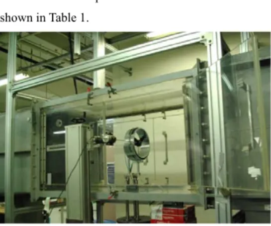
The experimental setup as shown in Fig.1 was prepared for investigation of tip clearance effects on performnace characteristics of ducted fans. Three dimensional flow fields were measured from hub to tip at outlet of ducted fans.The analysis of data acquired by 45° calibrated inclined hotwire anemometer was done by using PLEAT (Phase Locked Averaging Techniques) and three non linear differential equations were solved by using Newton-Rhapson numerical method. The velocity calibration of slanted hotwire is done by adopting method of Grand and Kool where as yaw angle calibration was done on a wide range of probe angle -90
~ +90 at fixed velocity.
Three ducted fans having tip clearance of 1,2,3 mm respectively are tested with the same rotor size of 248
*** Jinsoo Cho
Professor: Hanyang University E-mail: [email protected]
TEL: (02) 2220-1716 FAX: (02)2294-0547
- 395 -
한국추진공학회 2009년도 추계학술대회 논문집 pp.395~398 2009 KSPE Fall Conference
mm dia.Detailed specifications of these ducted fans are shown in Table 1.
Fig 1. Experimental Setup of tested fans Table 1. Detailed Specifications of tested fans
Ducted Fans A B C
Duct Diameter (mm) 250 252 254
Hub Diameter (mm) 58 58 58
Tip Clearance (mm) 1 2 3
Tip Diameter (mm) 248 248 248
No. of blades 3 3 3
Rotational Speed (RPM) 5000 5000 5000
3. Results and Discussions
The most important design specifications for a small UAV ducted fans are hover performance, hover control in case of adverse winds and stall performance in propeller mode. The following results are presented in terms of hover performance, in each case of; the effects of tip gap are illustrated.
Fig.2 represents effects of tip clearance on axial velocity flow field at outlet of ducted fans A, B and C having tip gap of 01, 02, and 03 mm respectively. The contours plots are colored with velocity magnitude. As the tip gap is increased, axial velocity magnitude is decreased. This effect is more dominant near the tip and mid span of the blade as compared to hub section.
Moreover, the scales of axial velocity components are more affected by reducing the tip clearance level.
Fig. 3 shows the variation in magnitude and flow pattern of radial components of velocity with the effects of tip gap. Experimental results show that there is complex interaction between rotor tip and duct boundary layer appeared. The flow near the mid span of blade appears to be separated after passing through the rotor tip path line. Reducing rotor blade height to increase tip clearance had considerable affect on magnitude of
velocity especially in axial flow direction.
G G G G
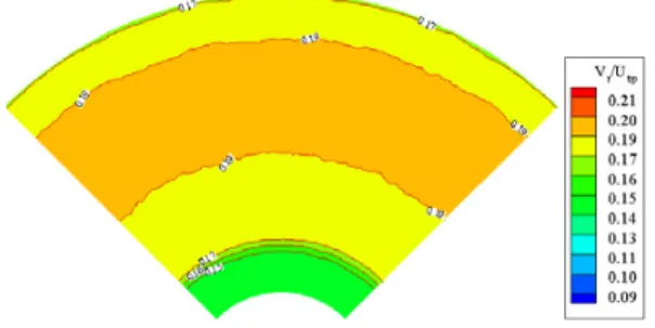
Fig.4 illustrates non dimensional tangential velocity
components of ducted fans A, B, C respectively. When the tip clearance gap is increased from 1mm to 3 mm, the magnitude of all three components of velocity at outlet of the ducted fans is decreased. By studying the detail of the flow pattern there are two different flow regions. One is the flow along the passage between the blades and the other one is cross flow through the tip gap, due to pressure difference between suction and pressure sides.
From the flow field results, it can generally be concluded that total magnitude of velocity produced by these three ducted fans decreases with the increase of tip clearance in the whole range of flow while mass flow area increases. Moreover, the trend of inflow also plays an important role in magnitude and pattern of exist flow.
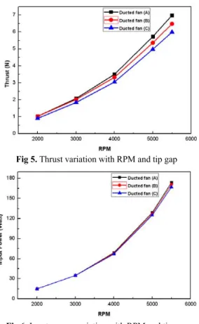
Fig.5 represents variation of thrust with rpm and tip gap level. Air which leaked through the blade tip clearance also decreases the efficiency and resulting thrust. Accordingly, the level of the blade tip clearance is made as small as possible to minimize this leakage flow without affecting the undesirable tip rubs. Furthermore, by enlarging the tip clearance level, the tip leakage flow from the higher pressure side to lower pressure side of the blade increase substantially in such fans, which results considerable thrust losses.
Fig.6 shows variation of input power to the ducted fans with the gradual changing of rotational speed.
For studying effects of tip clearance on fan input power, three types of tip clearance configurations were tested as described in Table 1. At low rotation speed from 2,000 to 3,000 rpm, this affect is not dominant. But as the rotational speed is increased this affect is also becoming more dominant. The ducted fan with smallest tip clearance consumes more input power for the same rotational speed.
Fig.7 shows static thrust generated by these ducted fans as functions of electric power input. The presented data provide estimates of the input power required for hovering flight and can be used for proper battery selection. As it is shown from the figure ducted fan having smallest tip clearance generates more thrust for the same input power.
Fig.8 represents coefficient of thrust as a function of rotational speed. The results are shown for 3 values of tip gap as defined in Table 1.and only one rotor size case is used for better comparison of obtained results.
For the smallest tip gap of 1 mm, the duct thrust developed is considerably higher than larger tip gap ducted fan at same high rpm.
- 396 -
<Axial Velocity component, type A>
<Axial Velocity component, type B>
<Axial Velocity component, type C>
Fig 2. Non dimensional axial velocity Contours
<Radial Velocity component, type A>
<Radial Velocity component, type B>
<Radial Velocity component, type C>
Fig 3. Non dimensional radial velocity Contours
<Tangential Velocity component, type A>
<Tangential Velocity component, type B>
- 397 -
<Tangential Velocity component, type C>
Fig 4. Non dimensional radial velocity Contours
Fig 5. Thrust variation with RPM and tip gap
Fig 6. Input power variation with RPM and tip gap
Fig 7. Thrust as a function of Input power
Fig 8. Thrust coefficient variation with RPM and tip gap
4. Conclusions
1. For the same rotational speed and same rotor size, tip clearance has considerable affects on velocity flow fields. Total magnitude of the velocity scale decreases with the increase of tip clearance in the whole range of the flow. However mass flow area is increased as the tip clearance level is enlarged.
2. Increasing tip cl earance l evel d ecreased the duct thrust dramatically and therefore resulted in decrease of total figure of merits of the vehicle.
3. For the same input power, ducted fans with small tip clearance generates higher value of thrust.
However at high rpm, it consumes high input power for same rotational speed.
4. In rotor and blade designing, tip clearance effects must be considered. However, the severity and magnitude of these effects may be quite different depending upon the geometry and operating conditions of the ducted fans. For getting better performance tip clearance level should be kept as small as possible
UG GAcknowledgement
͑ ͑ ͑ ͑ This study has been supported by the KARI under the KHP dual-use development program funded by the Ministry of Knowledge Economy.G
References
X