67-2 / J. W. Kim
IMID 2009 DIGEST •
Abstract
In this paper, the effect of a flow barrier and bypass on the cooling performance for a straight fin heat sink is presented. Both side directions and upward direction of bypass are controlled using various ducts which have different width and heights. In addition, a flow barrier is used to control flow toward heat sink. Through experiments, the distance from leading edge of a heat sink to a flow barrier is varied for various bypasses under fixed volume flow rate condition. This study shows possibility to improve cooling performance when bypass and a flow barrier exist.
1. Introduction
Nowadays, emitting heat per unit volume of electronic devices drastically increases. Because operating temperature of each component relates to lifetime and reliability, effective cooling is very important to guarantee performance and lifetime of devices. Generally, heat sink and fan are the most conventional devices in electronics cooling. Many researchers have investigated to optimize thermal performance of a heat sink. In addition, they have researched the effect of geometry and flow condition near a heat sink on the cooling performance of a heat sink. In most cases, optimization of heat sink geometry is limited to maximize thermal performance because available space to design a heat sink is restricted. Hence, when you optimize thermal performance of a heat sink, it is important to consider geometry in which heat sink will be fixed. In this study, the effect of a distance from a straight fin heat sink to adjacent side walls and upper wall on the cooling performance is investigated by experiments. In addition, to optimize thermal performance of a
straight fin heat sink, the effect of a flow barrier on the cooling performance for a straight fin heat sink is also investigated. This flow barrier is used to improve thermal performance of a straight fin heat sink and it can be made as a piece uniting it to a duct.
2. Definitions and experimental apparatus
In this study, it is assumed that flow toward heat sink is uniform and uniformity of velocity is checked before experiment. Thin film heater is used to heat bottom of a heat sink and heat loss is neglected.
To verify thermal performance of a heat sink, thermal resistance of a heat sink is used. Total thermal resistance consists of Rfin and Rflow as shown in equation1.
q
T
T
R
=
base,max−
in flow fin in b b baseR
R
q
T
T
q
T
T
+
=
−
+
−
=
,max (1) Fig. 1 Definition Tip clearance, s Channel width, Wc Fin thickness, Wf Fin height, hf Base plate width, WOptimization of a straight fin heat sink in 3D LCos projector
considering bypass flow and a flow barrier
Kim Jin Wook
1, Kim Sang Hoon
2and Lee Seung Gyu
21
LG electronics display laboratory. 16 Woomyeon-Dong, Seocho-Gu,
Seoul, Korea
Tel.:82-2-526-4191, E-mail:[email protected]
Key Words : Bypass, tip clearance, flow barrier, straight fin heat sink, thermal resistance
67-2 / J. W. Kim
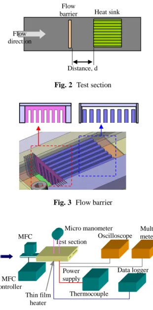
• IMID 2009 DIGEST Fig. 2 Test section
Fig. 3 Flow barrier
Fig. 4 Experimental apparatus
Table 1. Geometry of a heat sink and experimental condition
Inlet Q 10, 15, 20SLM Boundary
condition Input heat 7±0.15 W Width 30 Length 32 Base plate (mm) Thickness 2 Number 8 Thickness 2 mm Channel W 2 mm Fin Height 8 mm Height 8, 9, 10, 11 Duct (mm) Width 31, 32, 34, 36
In this study, thermal performance of a straight fin heat sink is verified for various tip clearance and bypass in ducts. Heat is applied to the base plate of a heat sink by the thin film heater. To check input heat, current and voltage are measured by oscilloscope and multi meter.
Volume flow rate is controlled by MFC(Mass flow controller). To check uniformity of velocity toward a heat sink, pressure drop is measured at 5 points with micro manometer. Bypass is varied at 1, 2, 4, 6mm and tip clearance is also varied at 0, 1, 2, 3mm. Shape of a flow barrier is the same as the area, where fluid flows between fins in a straight fin heat sink. The distance between a straight fin heat sink and a flow barrier is also changed from 1 to 5mm.
To measure temperature of a heat sink, 5holes are made on the bottom of a heat sink and T type thermocouples are inserted into each hole.
3. Results and discussion
Through experiments, pressure drop difference between maximum and minimum value is less than 0.01
mmH
2O
. Hence, flow toward a straight fin heatsink is uniform.
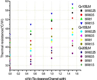
Thermal performance of a straight fin heat sink for various tip clearances is like fig. 5. According to the study by E.A.M. Elshafei[8], optimum tip clearance exists when Reynolds number is higher than 4000 which is turbulence regime. In this study, experiments are performed under the constant flow rate condition. Under the constant volume flow rate condition, as flow area increases, mean velocity decreases. As a result, optimum tip clearance does not exist under the constant volume flow rate condition or the same side bypass.
The effect of a bypass on the cooling performance for a straight fin heat sink is shown in fig. 6. Through experiments, when b/Wc is 0.5, optimum value exists. In this condition, thermal resistance decreases 6.2% compared to the condition when b/Wc is 0.25. Although volume flow rate changes, this tendency seems to be the same.
In general, when tip clearance or bypass exists, additional area that is unavailable when tip clearance does not exist to transfer heat is obtained. Therefore thermal performance improves relative to the condition without tip clearance. However, bypass makes velocity toward a heat sink decrease and volume flow rate into clear fluid region out of inter fin region increases. Hence, thermal performance may
Test section Data logger Power supply Thermocouple Oscilloscope MFC
Micro manometer Multi
meter Thin film heater MFC controller Flow
barrier Heat sink
Distance, d Flow
67-2 / J. W. Kim
IMID 2009 DIGEST • worsen because heat near the base plate, which is the
hottest region, does not transfer effectively. Considering these effects, the former effect conflicts with the latter one. When optimum value exists, effect of improving thermal performance by bypass flow prevails over the effect of worsening thermal performance due to decreased velocity.
0.0 0.2 0.4 0.6 0.8 1.0 1.2 1.4 1.6 3.2 3.6 4.0 4.4 4.8 5.2 5.6 6.0 Q=10SLM bWc0.25 bWc0.5 bWc1 bWc1.5 Q=15SLM bWc0.25 bWc0.5 bWc1 bWc1.5 Q=20SLM bWc0.25 bWc0.5 bWc1 bWc1.5 T h e rm a l r e si st a n ce ( oC/ W )
s/Wc (Tip clearance/Channel width)
Fig. 5 Thermal performance of a straight fin heat sink for various volume flow rates and tip clearances
0.0 0.2 0.4 0.6 0.8 1.0 1.2 1.4 1.6 3.0 3.2 3.4 3.6 3.8 4.0 4.2 4.4 4.6 4.8 5.0 5.2 5.4 5.6 5.8 6.0 Q=10SLM sWc0 sWc0.5 sWc1 sWc1.5 Q=15SLM sWc0 sWc0.5 sWc1 sWc1.5 Q=20SLM sWc0 sWc0.5 sWc1 sWc1.5 T h e rm a l r e si sta n ce ( oC/W ) b/Wc (Bypass/Channel width)
Fig. 6 Thermal performance of a heat sink for various volume flow rates and bypasses
To investigate the effect of a flow barrier on the
cooling performance, CFD is performed to compare volume flow rate that inflows clear fluid region and inter fin region. In this calculation, volume flow rate is 0.35CFM, s/Wc is 0.5 and b/Wc is 0.25. According to results, volume flow rate into inter fin region increases when flow barrier exists.
A flow barrier makes more fluid flow through inter fin region. In addition, if a flow barrier exists, flow area decreases. Hence, mean flow velocity through inter fin region increases and it improves thermal performance of a straight fin heat sink.
Table 2. Volume flow rate that flows in each part (Fluent)
d (Flow barrier) None 4mm
Q CFM Ratio (%) CFM Ratio (%)
Inlet 0.35 100 0.35 100
Clear fluid 0.07 18.3 0.03 9.4 inter fin 0.29 81.7 0.32 90.6
Fig. 7 shows effect of a volume flow rate and the distance from a heat sink to a barrier on the thermal performance of a heat sink when a flow barrier exists. In these experiments, b/Wc is 0.25 and s/Wc is 0. Through experiments, thermal performance of a heat sink improves as volume flow rate increases when a flow barrier exists.
Fig. 7 Relation between thermal performance of a heat sink and position of a flow barrier
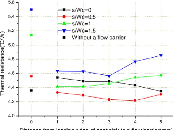
Fig. 8 shows the effect of a tip clearance on the cooling performance of a heat sink when a flow barrier exists. In these experiments, volume flow rate
0 1 2 3 4 5 6 2.8 3.0 3.2 3.4 3.6 3.8 4.0 4.2 4.4 4.6 Q10SLM Q15SLM Q20SLM
Without a flow barrier
T h er ma l r e s ist a n ce ( oC/ W )
67-2 / J. W. Kim
• IMID 2009 DIGEST is 10SLM, b/Wc is 0.25.
At first, if a flow barrier exists, optimum tip clearance exists whether tip clearance exists or not. Secondly, as tip clearance increases, improvement of thermal performance due to a flow barrier increases. Thirdly, when bypass and tip clearance are long, a flow barrier is effective to improve thermal performance of a straight fin heat sink.
Through experiments, when s/Wc is 0.5, thermal performance is optimized. It means that optimum tip clearance exists. As explained in table 2, a flow barrier makes volume flow rate into inter fin region increase. In addition, because heat transfer on fin tips is possible, thermal performance improves when tip clearance exists. This is also the same in the case when bypass exists.
0 1 2 3 4 5 4.0 4.2 4.4 4.6 4.8 5.0 5.2 5.4 5.6 s/Wc=0 s/Wc=0.5 s/Wc=1 s/Wc=1.5
Without a flow barrier
T h e rm a l res is tanc e( o C/ W )
Distance from leading edge of heat sink to a flow barrier(mm)
Fig. 8 Effect of flow barrier position and tip clearance on the cooling performance of a heat sink
As tip clearance increases, volume flow rate out of inter fin region also increases and it makes thermal performance of a heat sink worsen. However, a flow barrier makes volume flow rate into inter fin region increase. Hence, a flow barrier can improve thermal performance of a straight fin heat sink when bypass is long.
When fluid flows toward a heat sink, fluid that passes a flow barrier accelerates and more fluid flows through inter fin region. In this case, recirculation occurs behind the flow barrier and velocity decreases as flow develops. If distance from a flow barrier to a heat sink increases, flow develops again and it can not improve thermal performance of a heat sink. However, if distance from a flow barrier to a heat sink is short, pressure drop increases and thermal performance of a heat sink worsens. As a result, optimum distance from a flow barrier to a heat sink exists.
4. Summary
Through experiments, results are as follows.
1) When the ratio of bypass to channel width is 0.5, thermal resistance is minimized.
2) As volume flow rate increases, a flow barrier is more effective to improve thermal performance of a straight fin heat sink
3) When a flow barrier exists, optimum tip clearance and optimum side bypass exists.
4) When the bypass is longer than 1.5 times the channel width, bypass is effective.
5) Optimum distance from leading edge of a straight fin heat sink to a flow barrier exists.
6) As the ratio of tip clearance to channel width increases, optimum distance from leading edge of a straight fin heat sink to a flow barrier decreases.
Acknowledgement
This study was supported by LG electronics.
5. References
1. H. Shaukatullah, Wayne R. Storr, Bernt J. Hansen, Michael A. Gaynes., 12th IEEE Semi-Therm Symposium, pp. 151-163. (1996)
2. KEI S. Lau and Roop L. Mahajan, IEEE Transaction on Components, Hybrids, and Manufacturing Technology, Vol. 12, No. 4, pp. 757-765. (1989)
3. Saad A. El-Sayed, Shamloul M. Mohamed, Ahmed M. Abdel-latif, Abdel-hamid E. Abouda, Experimental Thermal and Fluid Science, Vol.26, pp. 879-900. (2002)
4. O. N. Sara, Energy Conversion and Management, Vol. 44, pp. 1787-1803. (2003)
5. O. N. Sara, S. Yapici, M. Yilmaz, Int. Comm. Heat Mass Transfer, Vol. 28, No.5, pp. 617-630. (2001) 6. Jung Yim Min, Seok Pil Jang, Sung Jin Kim, Int. J.
Heat and Mass Transfer. pp. 1099-1103. (2004) 7. Jin Wook Kim, Master thesis, pp.23-42 (2004) 8. E.A.M. Elshafei, Applied thermal engineering,
pp.2233-2242. (2007)
9. Octavio Leon, Gilbert De Mey, Erik Dick, Microelectronics reliability, pp1101-1111 (2002)