ISSN 2465-8111 DOI http://dx.doi.org/10.18770/KEPCO.2015.01.01.115
Screening of Spray-Dried K 2 CO 3 -Based Solid Sorbents using Various Support Materials for CO 2 Capture
Tae Hyoung Eom
*, Joong Beom Lee
*†, Jeom In Baek
*, Chong Kul Ryu
b**, Young Woo Rhee
***††
* KEPCO Research institute, Korea Electric Power Corporation,105 Munji-Ro, Yuseong-Gu, Daejeon 34056, Korea
** Korea Carbon Capture and Storage Assocoation, 599 Kwanak-ro, Kwanak-ku, Seoul, 311-414, Korea
*** Department of Chemical Engineering, Chungnam National University, Daejeon, 305-764, Korea
† E-mail: [email protected]; Tel.:+82-42-865-5254; fax: +82-42-865-5202
†† E-mail: [email protected];Tel.:+82-42-821-5688; fax: +82-42-822-8995
Abstract
K
2CO
3-based dry regenerable sorbents were prepared by spray-drying techniques to improve mass produced K
2CO
3-Al
2O
3sorbents (KEP-CO2P, hereafter), and then tested for their CO
2sorption capacity by a 2,000 Nm
3/h (0.5 MWe) CO
2capture pilot plant built for Unit 3 of the Hadong thermal power station in 2010. Each of the sample sorbents contained 35 wt.% K
2CO
3as the active materials with various support materials such as TiO
2, MgO, Zeolite 13X, Al
2O
3, SiO
2and hydrotalcite (HTC). Their physical properties and reactivity were tested to evaluate their applicability to a fluidized-bed or fast transport-bed CO
2capture process. The CO
2sorption capacity and percentage utilization of K
2CO
3-MgO based sorbent, Sorb-KM2, was 8.6 g-CO
2/100 g-sorbents and 90%, respectively, along with good mechanical strength for fluidized-bed application. Sorbs-KM2 and KT were almost completely regenerated at 140°C. No degradation of Sorb-KM by SO
2added as a pollutant in flue gas was observed during a cycle test.
Keywords: CO2capture, Dry regenerable solid sorbent, Flue gas, Fluidized-bed reactor
I. INTRODUCTION
Carbon capture and storage (CCS) from large point sources such as thermal power plants is one option to reduce anthropogenic carbon dioxide emissions. Fossil power plants are the main source of CO
2emissions throughout the world, contributing approximately 40% of total global emissions. Coal- fired power plants alone contribute approximately 70% of the emissions from fossil power plants [1].
The Intergovernmental Panel on Climate Change (IPCC) predicts that anthropogenic CO
2emissions could be reduced by 80~90% for a conventional fossil fuel-fired power plant installed with CCS technologies [2].
CCS technologies applicable to the power generation sector can be categorized as post-combustion capture (mainly CO
2separation from N
2), pre-combustion capture (CO
2/H
2) and oxy combustion including chemical looping combustion (CLC), based on the power system. Considerable attention has been focused on cost-effective and energy-efficient CCS techniques such as wet scrubbing using amine solution, cryogenic and membrane, etc. One of the advanced concepts for CO
2capture is a chemical absorption process with dry regenerable solid sorbents [3]. This technology was proposed to overcome the wet scrubbing process.
The CO
2capture process using alkali metal carbonate based solid sorbents consists of two reactors of carbonation and regeneration. This process can be used to treat large volume of flue gases from fossil power plants. This process has several advantages over other processes: better gas contact with smaller sorbent particles, ease of sorbent make-up and removal, easy control of the exothermic carbonation reaction temperature, and continuously steady operation.
The following reaction proceeds in each reactor [4][5]:
Carbonation: M
2CO
3+ CO
2+ H
2O ↔ 2MHCO
3+ Heat (1)
Regeneration: 2MHCO
3↔ M
2CO
3+ CO
2+ H
2O (2) Here, M denotes Na or K, and the reaction enthalpy of Eq.
(1) for Na and K is -132.60 and -141.17 kJ/mole respectively.
Lee, et. al. [6]-[10] reported alkali metal-based sorbents using Al
2O
3, activated carbon, TiO
2, MgO, ZrO
2and SiO
2, etc.
as supporters with various preparation methods. The supporter has the important role of carbonation and regeneration.
KEPCO Research Institute (KEPRI) is developing regenerable sorbents using K
2CO
3with a spray dryer method applicable to post-combustion CO
2capture, with the process developer, Korea Institute of Energy Research (KIER). In 2006 and 2007, KIER’s 2 Nm
3/h and 100 Nm
3/h (0.6 ton CO
2/d) circulating fluidized process using the developed K-based solid sorbent called KEP-CO2P, supplied from KEPRI, continuously achieved 80% CO
2removal from simulated flue gas and 85%
removal from flue gas, respectively. In 2010, the 2,000 Nm
3/h (0.5 MW) capture process was installed into the slip stream of the flue gas of a coal-fired power plant of Korea Southern Power Co., Ltd. (KOSPO) located in Hadong, Korea, and has been evaluated for various operation conditions and sorbents.
KEPRI has tried to develop a K
2CO
3-based solid sorbent
able to maintain initial performance, chemical durability, and
good physical properties. This work presents the CO
2sorption
capacity and regenerability as well as the physical properties of
seven K
2CO
3-based solid sorbents. The sorbents were prepared
using a spray-dryer, with a focus on their application to a fast
fluidized-bed reactor process and the reactivity was tested by
thermogravimetery analysis (TGA).
116
II. EXPERIMENTAL A. Sorbent Preparation
The sorbent was produced using a spray-drying method which is easily scalable to commercial quantities in batches of approximately 6 kg. The preparation process consists of several steps: 1) mixing the raw materials in water with dispersants, 2) comminution of the raw materials and colloidal slurry preparation with a high-energy bead mill, 3) spray drying to form a spherical-shaped green body, followed by pre-drying and calcinations steps. Among these process the slurry preparation is the most important step for obtaining spherically-shaped sorbent without defects, such as doughnut, hollow, or dimple shapes.
The raw materials used included commercial grade K
2CO
3(Dongyang Chemical Co., Korea) as an active material, and various materials such as Al
2O
3, TiO
2, MgO, Zeolite 13X, hydrotalcite (HTC) and SiO
2used as support materials. Seven formulations contained approximately 35 wt.% of the solid active material. All of the solid materials were mixed in a batch with water as solvent by a mechanical mixer, and then each formulation was comminuted with a ball mill. The solid concentration, viscosity and pH of these colloidal slurries were controlled by the addition of organic additives such as dispersants or water, to maintain them in the form of a homogeneous, dispersed and stable fluid, in this comminution step. The comminuted slurries were spray-dried to form the spherical solid sorbent and then the sorbents were calcined in a muffle furnace at 500~650°C under an air atmosphere. These sorbents were designated the Sorb-K series with each support material.
B. Physical Characterization
The physical properties for each seven sorbents were characterized through standard test methods. A packing volume/tap density device (Single Autotap, Quantachrome), ASTM D 4164-88, and sieve shaker (Meinzer II), ASTM E-11, were used to determine bulk density, size distribution and average particle size, respectively.
The attrition resistance for the circulating fluidized-bed process was evaluated using a modified three-hole air jet attrition tester based on the ASTM D 5757-95. The attrition index (AI) was determined to be 10 slpm (standard l/min) over 5 h periods, as described in the ASTM method. The attrition index is the percentage fines generated over 5 h:
AI (5) = total fines collected for 5 h/amount of the initial sample
(50 g) × 100 (3)
The corrected attrition index (CAI) is the percent of fines generated over 4 h using the following equation:
CAI (5) = (total fines collected for 5 h - fines collected for first 1 h)/(amount of initial sample - fines collected for first 1 h) × 100
(4)
The AI (CAI) of fresh Akzo and Davison FCC catalysts, which were used as references, were 22.5(18.0)% and 18.4 (13.1)%, respectively, under the same conditions. In a circulating fluidized-bed CO
2capture process, materials with an
AI < 20% would be acceptable for a transport reactor or a bubbling fluidized-bed reactor for use with flue gas under atmospheric pressure. A lower AI or CAI indicates a better attrition resistance of the bulk particles [5].
C. Chemical Reactivity
The chemical reactivity of the sorbents was assessed using a simultaneous thermal analyzer (Rheometrics Scientific STA 1500), which has the dual functions of thermogravimetry analysis (TGA) and differential scanning calorimetry (DSC).
Carbonation was performed from 65°C to 85 °C at every 5°C, respectively. The compositions of simulated flue gas were 14.4 vol.% CO
2, 5.4 vol.% O
2, and 10 vol.% H
2O with the remainder being N
2, as in Table 1. The total flow rate was 60 mL/min (standard) and the amount of each sample was about 10 mg.
After CO
2sorption was completed, regeneration was tested at 140°C and 180°C and the heating rate was 5°C/min. The regeneration gas was a neat N
2gas with a flow rate of 60 mL/min (standard). The reaction test was performed to confirm the reproducibility of the results at least three times for each sorbent and it was found that each reactivity was similar in the
Table 1. TGA test conditions and gas compositions Conditions Carbonation Regeneration Gas composition [vol.%] CO
2O
2H
2O N
214.4 5.4 10.0
70.2 100
Temperature [°C] 65-85 120-180
Pressure ambient ambient
Total gas flow rate [mL/min] 60 60
Fig. 1. The Diagram of the TGA gas supply system. TIC:
temperature indicator and controller, EB: electronic balance.
repeated test.
A schematic description of the modified TGA is presented in Fig. 1. Water, quantitatively fed from a syringe pump, is contacted with the reaction gas or carrier N
2gas. At this time, they are heated by TIC 1 to simulate flue gases at 140°C and then the simulated gases flow to a 4-port valve. The simulated gases and regeneration gases are switched through the 4-port valve. The temperature of the simulated flue gases from the 4- port valve to the TGA inlet was controlled by TIC 2 at 100~120°C. Finally, the reaction gases were fed to the modified inlet line of the furnace which was heated with TIC3 without condensation at reaction temperature.
To obtain the net CO
2sorption capacity from the (CO
2+ H
2O) absorption by the solid sorbents, the TGA cycle test was divided into four different sequential steps: Step I is the baseline with the neat N
2gas. Mixture (H
2O + N
2) gas was introduced at the onset of Step II until there was no more TGA weight gain from H
2O adsorption. At the beginning of Step III, a simulated flue gas was introduced to perform the normal TGA experiment, in which the active component mainly reacts with a stoichiometric amount of CO
2and H
2O. Finally, the sorbent was regenerated by dry N
2while releasing CO
2in Step IV.
The CO
2sorption capacity, L
CO2, of a sorbent expressed in weight percentage was defined as:
100
2 2
2 2
0 0
1
O H CO
CO
CO
M M
M m
m
L m (1)
where m
0is the initial mass of a solid sorbent and m
1is the mass measured without weight change by TGA in Step III. M is the molecular weight of CO
2and H
2O, respectively.
III. RESULTS AND DISCUSSION
All the prepared sorbents were tested to screen a candidate applicable to the capture process for physical properties such as
mechanical strength, particle size, and tap density and so on as
well as chemical reactivity. Then, the various experiments for chemical reactivity were carried out.
A. Physical properties
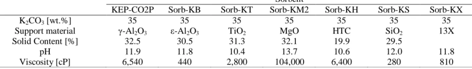
The slurry properties of the seven spray-dried sorbents are summarized in Table 2. Although the viscosity of Sorb-KM2 was approximately 104,000 cP, which was significantly higher than the normal value used in the spray-dryer process, in this work a commercial pump was used and the high viscosity slurry was successfully spray-dried.
The shape of the sorbents was spherical without dimple, doughnut, or hollow shapes, as in Fig. 2. Table 3 shows the physical properties of the seven sorbents. Most of the sorbents showed suitable physical characteristics, average particle size and particle size distribution, and tap density, for the 0.5 MW capture process. Fig. 3 shows the AI (5) and CAI (5) of each sorbent. The attrition resistance as well as the chemical reactivity is two of the critical parameters in the development of a sorbent, because any attrition of the sorbent causes the loss of active material resulting in lower product quality. Attrition can Table 2. Physical Properties of the developed K
2CO
3-based sorbents
Sorbent
KEP-CO2P Sorb-KB Sorb-KT Sorb-KM2 Sorb-KH Sorb-KS Sorb-KX
K
2CO
3[wt.%] 35 35 35 35 35 35 35
Support material γ-Al
2O
3ε-Al
2O
3TiO
2MgO HTC SiO
213X
Solid Content [%] 32.5 30.5 31.3 32.1 19.9 29.5
pH 11.9 11.8 10.4 13.7 10.6 12.0 11.8
Viscosity [cP] 6,540 440 2,800 104,000 6,400 280 810
Table 3. Slurry properties of the developed K
2CO
3-based sorbents Sorbent
KEP-CO2P Sorb-KB Sorb-KT Sorb-KM2 Sorb-KH Sorb-KS Sorb-KX
Tap Density [g/cc] 0.98 0.97 1.11 0.99 1.11 1.05 0.72
Average Particle Size [μm] 103 126 118 113 111 124 148
Particle Size Distribution [μm] 37-303 49-303 42-303 19-300 16-300 19-280 57-355
Fig. 2. SEM images of the solid sorbent calcined at 550°C (Left: KEP-CO2P, Middle: Sorb-KT, Right: Sorb-KM2)
Fig. 3. The attrition index (AI) of the developed K
2CO
3-based sorbents calcined at 550°C.
KEP-CO2P Sorb-KB
Sorb-KT Sorb-KM2
Sorb-KH Sorb-KS
Sorb-KX
Attrition Index [%]
0 10 20 30 40 50 60
AI (5) CAI (5)
118
also result in the need for additional filtration and cause plugging as well as affect the fluidization and solid circulation properties [13]. The AI (5) results of the developed K
2CO
3-
based sorbents, except Sorb-KX, were measured to be less than 11% as shown in Fig. 3. Especially, the AI (5) of sorb-KT was nearly zero like KEP-CO2P used in 0.5 MW test-bed. This means that three of the developed sorbents had suitable mechanical strength for the CO
2capture process.
B. Chemical reactivity
Seven developed sorbents were tested for CO
2sorption capacity. To obtain the net CO
2sorption capacity of the solid sorbents from their absorption of CO
2and H
2O, the TGA cycle
test was divided into four different sequential steps: Step I is the baseline with the dry N
2gas. A mixture of H
2O and N
2gas was
introduced at the onset of Step II until there was no more TGA weight gain by H
2O adsorption. At the beginning of Step III, a simulated flue gas was supplied to perform the normal TGA experiment, in which the active component mainly reacts with a stoichiometric amount of CO
2and H
2O. Finally, the sorbent was regenerated by dry N
2.
To screen the chemical reactivity of the prepared sorbent, sorbents were dried at 180°C and then the 2 cycle carbonation and regeneration test was carried out at 70°C and 180°C based on KEP-CO2P's results, respectively. Fig. 4 shows the sorption capacities of these sorbents. Especially, in the case of Sorb-KT, the sorption capacity maintained its initial value. Based on the results, 6 cycle sorption tests were carried out for Sorb-KT.
There was no degradation of CO
2sorption capacity during 6 cycles, as shown in Fig. 5.
Sorb-KT was not selected as a candidate to apply to the 0.5 MW CO
2capture test bed due to the lower performance than KEP-CO2P, although it showed excellent mechanical strength and no decrease in CO
2sorption capacity. The lower CO
2sorption capacity of Sorb-KT than KEP-CO2P was owing to drastic decreases in the active ingredient, K
2CO
3, in sorbent by new compounds such as K
2Ti
2O
5, K
2Ti
6O
13, and K
2Ti
4O
9, which were produced from K
2CO
3and TiO
2in the calcination process over 300°C [6]. On the other hand, the reason why the sorbent was no degradation of performance was that K
2CO
3in sorbent was only converted to KHCO
3and the new compounds were inactive with CO
2in simulated flue gas.
The CO
2sorption capacity of Sorb-KM2, K
2CO
3-MgO based sorbent, was higher than KEP-CO2P, and its regenerability which means percentage ratio of desorption capacity by CO
2sorption capacity was over 90%. In addition, their utilization expressed as a percentage of net CO
2sorption capacity by TGA and theoretical CO
2capacity, was about 90%.
The reaction rate constant was analyzed to compare the Fig. 4. The CO
2sorption capacity of the developed K
2CO
3-
based sorbents calcined at 550°C.
Fig. 5. The CO
2sorption capacity of Sorb-KT calcined at 550°C during 6 cycle.
KEP-CO2P Sorb-KB
Sorb-KT Sorb-KM2
Sorb-KH Sorb-KS
Sorb-KX CO2 Sorption Capacity [wt%]
0 2 4 6 8 10
1s t Cycle 2nd Cycle
Cycle Number [-]
1 2 3 4 5 6
CO2 Sorption Capacity [wt%]
0 1 2 3 4 5
Fig. 6. The effect of calcination temperatures on sorption capacity of Sorb-KM2.
Calcination Temperature [oC]
500 550 600 650
CO2 Sorption Capacity [wt%]
0 2 4 6 8 10
1s t Cycle 2nd Cycle
developed sorbent, Sorb-KM2, with KEP-CO2P used in 0.5 MW CO
2capture test bed for rate-based phenomenon. The reaction rate constant (k
c) of carbonation for KEP-CO2P and Sorb-KM2 was 0.216 min
-1and 0.356 min
-1, respectively.
To assess the effect of the calcination temperature, 500, 550, 600 and 650°C, on Sorb-KM2 under atmosphere, respectively, the carbonation test was examined at 70°C under the simulated gas conditions, which in general is the amount included in the flue gas from coal fired power plant, and the sorbent was regenerated at 180°C. As shown in Fig. 6, the results indicate the highest capacity when the calcination temperature was 550°C.
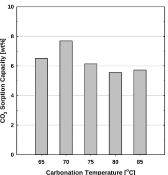
The dependence of the CO
2sorption capacity on the carbonation temperature for Sorb-KM2 calcined at 550°C was tested at every 5°C from 65°C to 85°C, respectively. Simulated flue gases were supplied at 60 ml/min STP. The results are shown in Fig. 7. The maximum sorption capacity shows at 70°C but the capacity abruptly decreased at temperatures over 75°C.
It was thought that the reaction rate of CO
2regeneration of K
2CO
3-MgO based sorbent was faster than the carbonation rate over 75°C.
The regeneration performances for Sorb-KM2 were tested at 120, 140 and 180°C under N
2based on the results of the KEP-CO2P used in the 0.5 MW CO
2capture process. After 70°C carbonation, the samples were heated at 2 °C/min. The results are compared in Fig. 8. The regenerability of Sorb-KM2 increased at the higher temperature. Although the regeneration occurred at 140°C, the K
2CO
3-MgO based sorbent was almost completely regenerated at temperatures near 180°C. This means that the temperature of regenerator have to be maintained higher than 180°C in order to efficiently attain CO
2removal in the capture process. If the regeneration in the process was operated lower than 180°C, the CO
2removal might be decreased because of the degradation of the CO
2sorption capacity.
Deactivation by SO
2in flue gases as well as the mechanical strength, chemical reactivity and the regeneration performance
is the one of the important factor in sorbent screening.
Deactivation by pollutant, SO
2, in flue gas was tested with the simulated flue gas including 40 ppm SO
2. The test was carried out during continuous 4 cycles. First, the simulated flue gases without SO
2as summarized in Table 1 was fed to TGA during 1 and 2 cycles and then the simulated flue gas including SO
2was used to compare the performances in 3 and 4 cycles. The sorbents after each reaction with CO
2were regenerated under N
2at 180°C. In order to distinguish the differences in the performance, the results of the CO
2sorption capacity containing the simulated gas without SO
2and the simulated flue gas including 40 ppm SO
2are presented in Fig. 9. The results showed that the degradation of the sorbents by SO
2was negligible. Therefore, if this sorbent would be selected as the sorbent to operate the 0.5 MW CO
2capture test bed, the SO
2concentration in the flue gas should be controlled below 40 ppm to prevent the contamination by SO
2.
IV. CONCLUSIONS
Seven K
2CO
3-based solid sorbents using various support materials were prepared by spray dryer method in 6 kg/batch, to improve the performance of KEP-CO2P. The physical properties of all sorbents, i.e. their shape, size, size distribution, bulk density, attrition resistance, etc., were characterized. All sorbents showed average particle sizes in the range of 103~148 μm and a size distribution of 16~355 μm which are appropriate for fluidized-bed application. The bulk density of the sorbents
Carbonation Temperature [oC]
65 70 75 80 85
CO2 Sorption Capacity [wt%]
0 2 4 6 8 10
Fig. 7. The carbonation temperature dependence of Sorb-KM2 calcined at 550°C.
Fig. 8. The performances of Sorb-KM2 calcined at 550°C based on regeneration temperature under N
2.
Fig. 9. The effect of SO in flue gas for Sorb-KM2.
Time [min]
0 20 40 60 80 100
Relative Weight Change (w/w0) [%]
88 90 92 94 96 98 100 102
120 oC 140 oC 180 oC
Cycle Number [-]
1 2 3 4
CO2 Sorption Capacity [wt%]
0 2 4 6 8 10
SO2 Free
40 ppm SO2 from 3rd 3 Cycle
120
![Table 1. TGA test conditions and gas compositions Conditions Carbonation Regeneration Gas composition [vol.%] CO 2](https://thumb-ap.123doks.com/thumbv2/123dokinfo/4901858.291653/2.935.476.865.100.697/table-tga-conditions-compositions-conditions-carbonation-regeneration-composition.webp)
![Fig. 6. The effect of calcination temperatures on sorption capacity of Sorb-KM2. Calcination Temperature [ o C]500550600 650CO2 Sorption Capacity [wt%]0246810 1 s t Cycle2nd Cycle](https://thumb-ap.123doks.com/thumbv2/123dokinfo/4901858.291653/4.935.493.837.140.476/calcination-temperatures-sorption-capacity-calcination-temperature-sorption-capacity.webp)