A Study on Optimal Quality Fabrication for the Tactile Sensation of Low Visibility Using 3D Printing
Hyeonsu Hana) and Junghyuk Koa)‡
Abstract
Most of the blind are low vision blinds due to injury or disease. As their vision decreases, they are experiencing inconvenience in their normal life and forgetting their memories with their family. The purpose of this study is to use Lithophane printing technology to help their normal life and to remember their family. Also, the manufactured 3D plates are to study the conditions that can be optimal understood through the tactile sense of low vision blind. When the low vision blind person understood the 3D plates, they chose three parameters that affect their tactile sense. And by comparing their tactile sense, the optimal condition results were found. This paper was concluded with (1) the round form that perceived as 3D objects, (2) the thin thickness similar to Braille, and (3) the high resolution that can be expressed in detail.
Keywords : Lithophane, Low vision blind, Tactile sense, Braille
I. Introduction
The definition of visual impairment, low vision and blindness used in the present study follow those given in the International Statistical Classification of diseases, in- juries and causes of death, 10th revision (ICD-10) : H54
where : (1) visual impairment includes low vision as well as blindness (2) low vision is defined as visual acuity of less than 6/18, but equal to or better than 3/60, or a corre- sponding visual field loss to less than 20 degrees in the better eye with best possible correction, In 2002, the num- ber of visual impairment with diseases and injuries was more than 161 million, of which about 80% (124 million) were classified as low vision blind [1,2].
As vision decreases, normal life for the low vision blind become difficult and sometimes impossible to work with- out any helps. The result can be depression, loss of self-es- teem, decreased motivation, and excessive dependence.
The most painful part of the low vision blind when their losing sight is the loss of their family’s faces or priceless memories. The low vision blind had a more positive impact
Copyright Ⓒ 2016 Korean Institute of Broadcast and Media Engineers. All rights reserved.
“This is an Open-Access article distributed under the terms of the Creative Commons BY-NC-ND (http://creativecommons.org/licenses/by-nc-nd/3.0) which permits unrestricted non-commercial use, distribution, and reproduction in any medium, provided the original work is properly cited and not altered.”
a) Division of Mechanical Engineering, National Korea Maritime and Ocean University
‡Corresponding Author : Junghyuk Ko E-mail: [email protected] Tel: +82-51-410-4292
ORCID: http://orcid.org/0000-0001-5823-2857
※This research was supported by Basic Science Research Program through the National Research Foundation of Korea (NRF) funded by the Ministry of Education and Ministry of Science (2019R1G1A100 9980).
․Manuscript received October 16, 2019; Revised December 16, 2019;
Accepted December 16, 2019.
Special Paper
방송공학회논문지 제24권 제7호, 2019년 12월 (JBE Vol. 24, No. 7, December 2019) https://doi.org/10.5909/JBE.2019.24.7.1237
ISSN 2287-9137 (Online) ISSN 1226-7953 (Print)
on support about family and friends among the various sup- ports for normal life [3-5].
Recently, 3D printing technology has been used in the production of low vision blind aids, braille based tactile boards, tactile picture books, tactile maps and so on [6-8].
3D printing technology is a method of three-dimensional objects by stacking or bonding raw materials, as Additive Manufacturing (AM). It was also used in the aviation/auto- motive industry to prototype for design evaluation prior to mass production of the product. With patents related to the technology expiring, the 3D printing technology has con- verged with IT technology to create a wide range of appli- cations [9]. One of the most representative is the lithophane which is able to convert a 2D image to a 3D object.
Here we show an assisted 3D plate that can help the low vision blind to remember memories of family and friends by using lithophane 3D printing technology to feel appear- ance through their memories’ pictures. We also study to optimize conditions of the 3D plate for the low vision blind’s tactile sensation. Before manufacturing the 3D plate, we consider the contrast of a picture’s image and the resolution with the 3D printer’s performance since it is dif- ficult to predict the highest quality if the number of pixels of picture’s image and resolution of the 3D printer are clearly different [9]. The tactile aid we suggested will help people with low vision and also it is possible to influence on reducing depression and dependence [4,8,9].
In this paper, we edit a picture image that can appear as a distinct 3D surface using the ‘Paint’ and ‘Capture tools’ in the windows assistant program. In order to find the optimization conditions, we adjust the ratio of the reso- lution between the picture image and the 3D printer in the
‘Lithophanemaker’ software, and then convert the image file to STL file. There are a number of parameters that can affect the visually impaired when they sense the 3D surface through sense of touch. Among them, three parameters that are most influential were determined: (1) two forms pro- duced: round or flat, (2) three thicknesses of the displayed
surface: 2mm, 3mm or 4mm, (3) three reduced resolution percentages from the original picture : 30%, 50% or 70%.
The 3D plate of the 18 different conditions manufactured is compared the appearance of the person through the tac- tile sense of the low vision blind, then we show the result of the 3D plate with the optimization condition.
II. Image processing and Converting
Figure 1 (A) is one’s picture of a family or memories of the low vision blind. We remove unnecessary parts of the comparison about the tactile sense, such as the back- ground, using cutting and background removal tools in the Microsoft Word program before converting the Figure 1 (A) to a 3D surface. Also, to show the 3D surface clearly, we change the picture color to zero and increase the con- trast to 40%. If the contrast is too high, 30% to 40% is suitable, because the bright part of the person’s skin over- laps the background. When editing is complete, the image to be used for the lithophane printing technique is generated. This is shown in Figure 1 (B).
Fig. 1. Image processing using Microsoft office (A) Original image, (B) Edited image
1. Conversion of edited image
In order to fabricate a lithophane printing as shown in
Figure 1 (B), converting the file extension from the picture image to the 3D form (from JPG to STL) is necessary.
When converting a 3D plate, we consider the three of most influential parameters among the various factors that the low vision blind understand through tactile sense; (1) two forms produced: round or flat, (2) three thicknesses of the displayed surface: 2mm, 3mm or 4mm, (3) three reduced resolution percentages from the original picture : 30%, 50% or 70%. A total of 18 STL files were converted and a ‘Lithophanemaker’ program was used as the STL files conversion program.
To observe how the surface thickness and resolution change, we implemented to do experiments with round and flat shapes at 60 degrees as shown in Figure 2. The printing mark is an interface that occurs when 3D printing is further stacked. For flat shapes, printing mark that aren’t in the picture will degrade the resolution. However, in the case of round shape, the experiment confirmed that the printing mark does not significantly reduce the resolution due to the bending. In addition, if the curvature is more than 60 de- grees, even if the round shape is raised, the deformation of the photo becomes large and does not match the purpose of Lithophane.
Fig. 2. Curvature of 3D plate (A) flat_0 degree, (B) round_60 degree
As shown in Figure 3, the thickness of the plate is com- pared to the thickness from 2 mm to 4 mm at 1 mm spac- ing in which a person’s appearance is all expressed. When
the 3D plate is manufactured, if a thickness of 4mm or more is output without setting a support for surface repre- sentation, a partial flow of the raw material (filament) occurs. In addition, according to the braille specification, the interval between braille is 2.5 ~ 4.5 mm, and therefore three thickness are considered (2mm, 3mm, 4mm).
Fig. 3. Thickness of the displayed surface of flat plate (A) 2 mm, (B) 3 mm, (C) 4 mm
As shown in Figure 4, resolution is the number of pixels per inch (ppi). At present, the front resolution of the mobile phone (based on ‘Galaxy S8’) with the lowest resolution among the resolutions of the front and back pictures of the camera and mobile phone is about 576 ppi. However, the 3D printer’s x/y resolution is about 450 ppi, making it im- possible to manufacture images of conventional resolution.
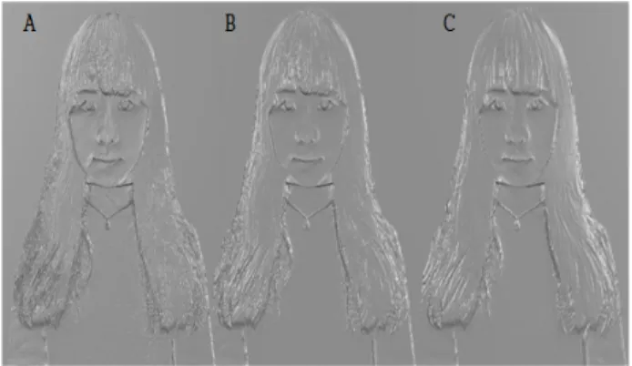
Fig. 4. Reduced resolution percentages from the original picture (A) 30%, (B) 50%, (C) 70%
III. 3D lithophane plate fabricating
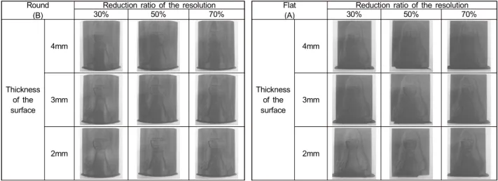
Using a 3D printer (Makerbot Z18), we produced the 18 plates shown in Table 1. In order to make precise compar- isons of visually impaired people at the same high pre- cision as the photographs, 3D surface of human shape to be used in this paper needs to be set up software of 3D printer before production. For the smoothness and rigidity of the 3D surface, we considered the internal temperature of the printer, the speed of the extruder when it is extruded and moved, the amount of internal infill of the product, and the number of shells. Table 1 shows 3D plates manufac- tured with 18 different conditions.
1. Temperature in the printer chamber
If the temperature of the printer chamber is equal to or lower than room temperature, the plastic may contract ir- regularly due to the difference in temperature between day and night, and the edges of the printed object may swell.
We set the temperature to 40 degrees Celsius, higher than the room temperature.
2. Speed of the extruder
If the speed of the extruder when it is extruded and
moved is equal to or faster than the speed of the extrusion speed of the filament, the filament cannot build up the layer and the output may be disturbed because filament can move before it is attached to the layer. So, the filament can be output as a partial support of the surface. Because the surface of these is difficult to make accurate compar- isons, we set speed to 70 mm/s which is half the original setting (150 mm/s).
3. Amount of infill
The thinnest thickness of the 3D surface is 3 mm. If the amount of filament infill filled in this internal space is small, the output may be broken by the hand. However, if the amount of infill becomes unnecessarily large, the in- fill pattern may slightly protrude on the surface of the print and may affect the surface shape. We set the amount of infill to 50%.
4. Number of shells
If the number of shells in the output is made to be one line, the surface of the output can be easily broken as if the amount of infill is small. However, when the number of shells becomes unnecessarily large, printing takes a long
Table 1. Output for 18 parameters (A) Flat, (B) Round Round
(B)
Reduction ratio of the resolution
30% 50% 70%
Thickness of the surface
4mm
3mm
2mm
Flat (A)
Reduction ratio of the resolution
30% 50% 70%
Thickness of the surface
4mm
3mm
2mm
time, so we made it with 2 lines.
Ⅳ. Analysis of manufacturing plates
As shown in Table 1, 18 plates were compared with 20 persons of those in their 40s to 70s who have obtained low vision, or 80% of those with visual impairments. We se- lected an image of a person who could be a family member or a friend of a low visually impaired person and did not mention the image of the person. This is to make sure that people with visual impairments can feel images through tactile sense. By classifying bending conditions, three dif- ferent resolutions (30%, 50% and 70%) were distinguished by thickness, and three different thicknesses (2mm, 3mm, 4mm) were compared according to resolution. This com-parison selection is shown in Figure 5.
Fig. 5. Tactile comparison option of the low vision blind
The reason for distinguishing the choices by resolution and thickness is to ensure that each best option is the same.
If the choice of two bests is the same, then the features of the images compared through the tactile sense are cor- rectly recognized, and if the choice of the best is greatly different, it means that the characteristics of the compared images are not correctly recognized.
1. Comparison results of Flat Plates
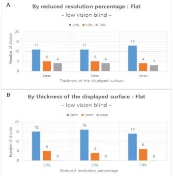
The statistics shown in Figure 6 (A) compares the thick- ness of the surface (2 mm, 3 mm, and 4 mm) with the standard of the reduced resolution ratio of the 3D plate in 9 flat samples. Of the reduced resolution ratios of each, low-vision blind people preferred 2mm most since the thickness of Braille is 0.6 ~ 0.8mm in Braille size specifi- cation, and the spacing between Braille characters express- ing one word is 2.5mm, 2mm and 3mm thickness are familiar. However, when the overall surface is felt, the
Fig. 6. Comparison with flat plates (A) reduced resolution percentage standard, (B) based on the thickness of the displayed surface thickness of 4 mm is considerably far from the floor layer,
so it takes a long time to recognize the shape, which makes it difficult to feel the overall shape. The statistics shown in Figure 6 (B) compares the reduced ratio of resolutions (30%, 50%, and 70%) with the standard of the thickness of the surface, to 3D plates in 9 flat samples. Of the thick- ness of each surface, 30% of the low-vision blind people preferred it most. 30% is a high resolution representation of a geometric image that is perceived as a more detailed and rugged surface, which is shorter than 70%, making it easier to recognize a partial contour.
2. Comparison results of Round Plates
The statistics shown in Figure 7 (A) compares the thick- ness of the surface (2 mm, 3 mm, and 4 mm) at the reference of the reduced resolution ratio. This result likewise favored 2mm in most cases. Figure 7 (B) compares the reduced ratio of resolution (30%, 50%, and 70%) with the standard of sur- face thickness. As a result, 30% was mostly preferred.
Fig. 7. Comparison with round plates (A) reduced resolution percentage standard, (B) based on the thickness of the displayed surface
3. Comparison results of 3D plate forms
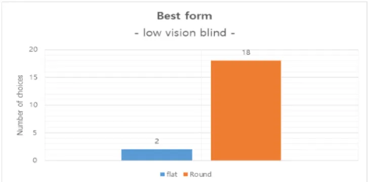
The most recognizable 2mm and 30% objects were com- pared to flat and round plates. When making the 3D plate, the flat plate is the same as the flatness of the picture, but it cannot withstand a slight vibration inside the printer, and the wave pattern appears as the output becomes higher.
This affects the tactile feel, so if you set a slight bend in the 3D plate, you can get a smooth surface with fewer wa- vy patterns, so you have to take a curved round of 60 degrees. The result of this comparison is Figure 8. The preference for round plates prevailed. When people with low vision recognized the shape of a round plate, they felt a circular three dimensional sense similar to that of a per- son rather than a flat plate. This makes the appearances of family and friends feel like a real figure.
Fig. 8. Comparison of 3D plate forms for optimal conditions
Ⅴ. Tactile comparison of non-blind
To compare the sensitivity of the tactile sense of the non-blind people with the sensitivity of the tactile sense of the blind, the same comparison was made based on the op- tions that blind people compared. The 3D-plate with the 18 parameter conditions, which compared with 20 non-blind persons, shown in Figure 6 was tested in the same conditions as those of the low-vision blind without regard to the age of the non-blind person. I did not mention
the image of the person. In addition, the parameters for bending were classified and three different resolutions (30%, 50% and 70%) were distinguished for each frame, and the same comparison option was used as in Figure 6, in which three thicknesses (2 mm, 3 mm and 4 mm) did.
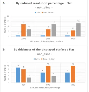
1. Comparison results of Flat Plates
The statistics shown in Figure 9 (A) compares the thick- ness of the surface (2 mm, 3 mm, and 4 mm) with the standard of the reduced resolution ratio of nine flat 3D plates. Of the reduced resolution ratios of each, non-blind people liked the thickness of 3 mm to 4 mm in a similar manner. When it is 2mm, it is too low to feel the shape itself. When it is 4mm, it is difficult to feel the other part because the eyes and mouth are big. The statistics shown in Figure 9 (B) compares the ratio of resolutions (30%, 50%, 70%), which are reduced from the standard of the thickness of the surface, to the flattened 9 3D plates. Of the thickness of each surface, the percentage of declining
Fig. 9. Comparison with flat plates (A) reduced resolution percentage standard, (B) based on the thickness of the displayed surface
resolution selected by the non-blind was slightly more than 50%. The non-blind people did not recognize the shape of the human image, and the difference in the ratio of reso- lution did not distinguish between 30% and 70%. Though 30% felt tougher, it did not affect the shape recognition.
2. Comparison results of Round Plates
The statistics shown in Figure 10 (A) compares the thickness of the surface (2 mm, 3 mm, and 4 mm) at the reference of the reduced resolution ratio. This result like- wise favored 3 ~ 4mm. The statistics shown in Figure 10 (B) compares the reduced ratio of resolution (30%, 50%, 70%), with the standard of the thickness of the surface. As a result, the ratio of the reduction resolution selected by the non-blind person among the thicknesses of the re- spective surfaces is slightly more than 50%.
Fig. 10. Comparison with round plates (A) reduced resolution percent- age standard, (B) based on the thickness of the displayed surface
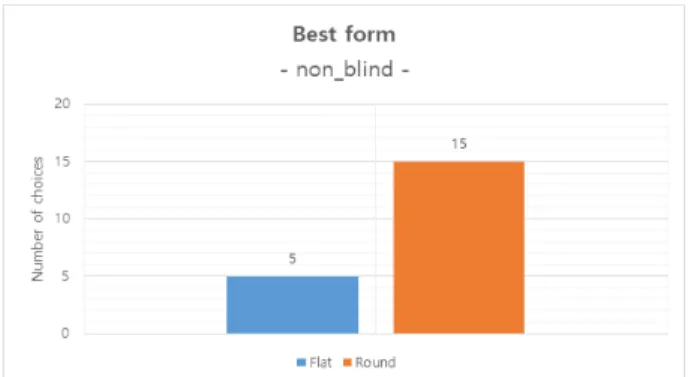
3. Comparison results of 3D plate forms
It compared flat and round plates to 3-4mm and 50% of
them that were most recognizable. Non-visual-impaired people also judged that the figures give them a more three-dimensional feel when they are round plates.
Fig. 11. Comparison of 3D plate forms for optimal conditions
Ⅵ. Comparison of the quality of non-blind and the low vision blind
First, the blind who judged the optimal quality of 2mm as compared with the thickness, recognizes the shape of the three plate correctly as a human figure, and the sensation of the hand has the sensitivity of the thickness of the braille (0.6 ~ 0.8mm) were not able to make accurate judgments about the shape of the 3D plate and the sensitivity of the hand was lower than that of the low visibility blind. Next, when compared with the reduced resolution ratio, the low vision judged 30% as the optimal quality. But the non-blind person selected 50% as the better quality. The non-blind person preferred a relatively 3 mm of relatively moderate thickness rather than 2 mm which is difficult to distinguish of the surface and rather than 4 mm which is too thick to judge thin parts. Finally, in comparison be- tween flat and round plates, both blind and non-blind peo- ple chose a round shape with a three-dimensional feel.
Ⅶ. Conclusions
Inspired by Braille for the visually impaired, we success-
fully created 3D Lithophane for the low vision blind. In order to optimize the results, the same portraits were made differently according to the parameters which are shape, thickness, and resolution. The most influential parameter was shape. The round shape was confirmed that the print- ing mark, which is inevitably generated when printing the portrait as it is, does not greatly affect the low vision blind.
In addition, the questionnaire of the visually impaired was confirmed that the printing mark not only damages the hu- man figure it self but also helps the low vision blind recog- nize the shape more clearly when the low vision blind touches the surface.
References
[1] S. Resnikoff, D. Pascolini, D. Etya'Ale, I. Kocur, R. Pararajasegaram, G. P. Pokharel, and S. P. Mariotti, “Global data on visual impairment in the year 2002“, Bulletin of the world health organization, Vol. 82, pp.
844-51, 2002.
[2] B. Thylefors, A. D. Négrel, R. Pararajasegaram and K. Y. Dadzie,
“Global data on blindness“, Bulletin of the world health organization, Vol.73, No.1, pp. 115, 2018.
[3] J. P. Reinhardt, “Effects of positive and negative support received and provided on adaptation to chronic visual impairment“, Applied Developmental Science, Vol.5, No.2, pp. 76-85, 2010.
[4] J. E. Moore, “Impact of family attitudes toward blindness/visual im- pairment on the rehabilitation process“, Journal of Visual Impairment and Blindness, Vol.78, No.3, pp. 100-6, 1984.
[5] J. P. Reinhardt, “The importance of friendship and family support in adaptation to chronic vision impairment“, The Journals of Gerontology Series B: Psychological Sciences and Social Sciences, Vol.51, No.5, pp. 268-78, 1996.
[6] L. A. D. Arbes, J. M. J. Baybay, J. E. E. Turingan and M. J. C. Samonte,
“Tagalog text-to-braille translator tactile story board with 3D printing“, The International Conference on Information Technology and Digital Applications, Vol.482, No.1, doi:10.1088/1757-899X/482/1/012023, 2019.
[7] J. Gual, M. Puyuelo, J. Lloverás and L. Merino, “Visual impairment and urban orientation. Pilot study with tactile maps produced through 3D printing”, Psyecology, Vol.3, No.2, pp. 239-250, 2014.
[8] T. Cavanaugh and N. Eastham, “The 3D printer as assistive technol- ogy“, Association for the Advancement of Computing in Education (AACE), DAAAM International Scientific Book, pp. 95-102, 2017.
[9] H. Brooks, M Lupeanu and T Abram, “Production of personalized lith- ophane lighting products using AM“, doi:10.2507/daaam.sci book.
2012.xx, 2012.
저 자 소 개
Hyeonsu Han
- Researcher
- LAMM(Laboratory of Advanced Multi-scale Manufacturing) in National Korea Maritime & Ocean University - ORCID : https://orcid.org/0000-0002-0223-044X
- Research interest : AM(Additive Manufacturing), Electrospinning, Tissue engineering, Biomedical engineering, Rehabilitation
Junghyuk Ko
- Assistant Professor
- LAMM(Laboratory of Advanced Multi-scale Manufacturing) in National Korea Maritime & Ocean University - ORCID : https://orcid.org/0000-0001-5823-2857
- Research interest : AM(Additive Manufacturing), Electrospinning, Tissue engineering, Biomedical engineering, Rehabilitation