* Corresponding Author: [email protected]
+ 이 논문은 2019~2020년도 창원대학교 연구비에 의하여 연구 되었음.
Manuscript received December 03, 2019 / revised January 20 ,2020 / accepted January 28, 2020
1) 창원대학교 전기공학과, 제1저자 2) 창원대학교 전기공학과, 제2저자 3) 창원대학교 전기공학과, 교신저자
1. Introduction
Recently, the structure and characteristics of three-phase multi-layer high-temperature superconducting coaxial (TPMHTSC) cables
PSCAD/EMTDC를 이용한 3 상 다층 고온 초전도 케이블의 모델링 및 과도 해석
+
(Modelling and Transient Analysis of a 3-Phase Multi-Layer HTS Coaxial Cable using PSCAD/EMTDC)
이 준 엽
1), 이 석 주
2), 박 민 원
3)*(Jun-Yeop Lee, Seok-Ju Lee, and Minwon Park)
요 약 3상 다층 고온 초전도 동축 케이블은 초전도 선재 사용량의 감소 및 케이블의 소형화와 같 은 이점 때문에 활발히 연구되고 있다. 3상 다층 고온 초전도 동축 케이블의 전기적 특성은 기존 초 전도 케이블과 차이를 가지므로 실제 시스템에 적용하기 위해 충분한 분석이 필요하다. 본 논문에서 는 PSCAD/EMTDC 기반 시뮬레이션을 통하여 22.9 kV, 60 MVA급 3상 다층 고온 초전도 동축 케이 블을 모델링하고 과도 특성을 분석하였다. 결과적으로 3상 다층 고온 초전도 동축 케이블에서 고장전 류가 발생하면 대부분의 고장전류가 구리 포머층을 통해 우회한다. 이때, 케이블 전체 온도는 약 5 K 증가하였다. 본 논문을 통해 3상 다층 고온 초전도 동축 케이블의 과도 상태에 대한 신뢰성을 확인할 수 있으며 향후 케이블의 실 계통 적용에 도움이 될 수 있다.
핵심주제어: 전력 케이블, 고온 초전도, 초전도 전력 케이블
Abstract Three-phase multi-layer high temperature superconducting coaxial (TPMHTSC) cable is being actively studied due to advantages such as the reduction of the amount of superconducting wire usage and the miniaturization of the cable. The electrical characteristics of TPMHTSC cables differ from those of conventional superconducting cables, so sufficient analysis is required to apply them to the actual system. In this paper, the authors modeled 22.9 kV, 60 MVA TPMHTSC cable and analyzed the transient characteristics using a PSCAD/EMTDC-based simulation. As a result, when a fault current flows in TPMHTSC cable, most of the fault current is bypassed through the copper former layers. At this time, the total cable temperature increased by about 5 K. Through this study, we can verify the reliability of the TPMHTSC cable against the transient state, and it can be helpful for the practical application of the cable in the future
Keywords: Power cable, High-temperature superconductor, Superconducting power cable
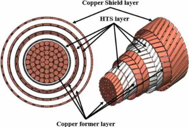
have been actively researched to maximize the advantages such as reduction of superconducting wires and miniaturization compared to other types of HTS cable. The TPMHTSC cable has a multi-layer coaxial structure, and the formers made of copper located at the cable center and at each conducting layer serve as a pathway to bypass the fault current (Lee, 2019).
The analysis of the transient state of the TPMHTSC cable itself basically requires before installation according to the impedance level of the cable which is dramatically changed in the case of quench at fault conditons, and the level of fault current will consequently be saturated on a certain value.
The saturated current value is decided by the condition of power system and the characteristics of the HTS tape wound as a HTS cable core. This requires a computer simulation, but currently there are no appropriate tools available to simulate the TPMHTSC cable, so as an alternative, the TPMHTSC cable can be modelled and transient characteristics can be analyzed using PSCAD/EMTDC (Hamajima et al., 2005; Bang et al., 2007; Kim et al., 2009; Ha et al., 2012).
In this paper, we modelled the TPMHTSC cable using PSCAD/EMTDC and analyzed the transient characteristics. The specifications of the TPMHTSC cable are 22.9 kV, 60 MVA, which is equivalent to the actual distribution cable specification for the Korean system.
The transient state of the TPMHTSC cable is modelled by creating components in PSCAD/EMTDC based on electrical and thermal characteristics. As a result, when a fault occurred in the TPMHTSC cable, most of the fault current was bypassed through the former layers and the overall temperature of the cable rose up to about 8 K. After the fault is cleared, the cable returns to its
normal state. The results of this study confirm the reliability of the fault current bypass of the TPMHTSC cable and can be used effectively in a real system application in the future.
2. Modeling of a TPMHTSC Cable in PSCAD/EMTDC
2.1 TPMHTSC Configuration
The TPMHTSC cable has a multi-layer structure consisting of HTS wires twisted clockwise and counter-clockwise along the same axis. Between the layers of the cable is filled with insulator material and there is a shield layer outside the conducting layer. The structure of the TPMHTSC cable is shown in Fig. 1.
Fig. 1 Structure of the TPMHTSC Cable
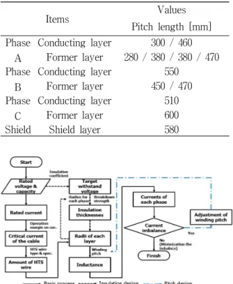
Table 1 and 2 show the obtained parameters through the process in Fig. 2.
2.2 Simulation Model of the TPMHTSC Cable in PSCAD/EMTDC
The components of PSCAD/EMTDC consist of a graphic tap, a parameter tap, and a script tap. The graphic tap is where the inputs and
the outputs of the circuit are assigned. The parameters tap allows the datasheet to receive input parameters from the user. The script tap calculates and performs orders, and uses FORTRAN language. The component of the TPMHTSC cable receives the operating current and temperature. It also receives the parameters such as the critical current, length, radii, and pitches of the cable from the user. Next the resistance, inductance and capacitance of the HTS wire determined by the shape of cable are calculated using the characteristic equation (Kiss et al., 1999; Kelley et al., 2001; Park et al.,
2004). Fig. 3 depicts the simulation model applied to a 1 km TPMHTSC cable of 22.9 kV/60 MVA class.
Fig. 3 Configuration of the TPMHTSC Cable in PSCAD/EMTDC
Fig. 4 The Physical Structure of the Homogeneous Substitute of the YBCO Tape
Fig. 4 shows the two-dimensional structure of the thermal model. The equivalent homogeneous thermal and electrical parameters of the top and bottom layers of YBCO wire are calculated as follows:
⋯
⋯
⋯
⋯
⋯
⋯
⋯
⋯
(1) (2) (3) (4)
Items Values
Voltage/capacity 22.9 kV/ 60 MVA Rated current 2200 A
Cable length 1 km
Table 1 Specifications of the TPMHTSC Cable
Items Values
Pitch length [mm]
Phase A
Conducting layer 300 / 460 Former layer 280 / 380 / 380 / 470 Phase
B
Conducting layer 550 Former layer 450 / 470 Phase
C
Conducting layer 510 Former layer 600 Shield Shield layer 580
Table 2 Pitch Length of the TPMHTSC Cable
Fig. 2 Design Process for the TPMHTSC Cable
where , and denote the heat capacity, thermal conductivity, mass density, electrical conductivity, and thickness of each layer, respectively; are the equivalent heat capacity, thermal conductivity, mass density, and electrical conductivity of the top or bottom homogenization layer.
The thermal model equation of a TPMHTSC cable can be expressed as follows:
where, , , , and are mass density, heat capacity, heat generated in the conductor, cryogenic cooling power.
(Zhang et al., 2018)
3. Simulation and the results
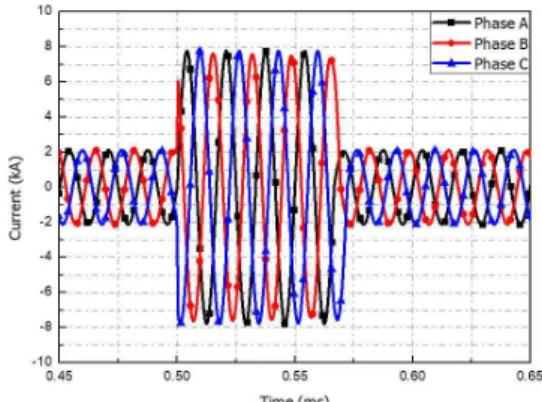
A 3-phase fault initiated at 0.5 sec and lasted for 0.05 sec. Fig. 5 and 6 show the current and temperature graphs characteristics of the TPMHTSC cable under the 3-phase fault In Fig. 5, all the phase currents are balanced.
When the fault occurs at 0.5 sec, the fault current of the TPMHTSC cable is unbalanced, even though the 3-phase fault is a balanced fault. Since the resistance of each layer of the TPMHTSC cable has different values for reasons of material and number of wires, each phase under the fault condition is affected by the different critical currents of each phase and the inherent imbalance status.
The TPMHTSC cable temperature distribution is also closely related to resistance. As shown in Fig. 6, when a fault occurs and an overcurrent flows through the HTS conducting layers of the TPMHTSC cable, the resistance of
the conducting layers are increased due to the superconducting characteristic. When this resistance is higher than the resistance of each former layer, the fault current on each TPMHTSC cable is bypassed through the former layers. The total temperature of the cable rose up to about 8 K and the highest temperature rise occurred in the former layer of phase B, the main passage of the fault current bypass. The results obtained here in the simulation can be changed by the variables such as the number of wires, materials of conducting layers and formers, pitch length, etc.
of the TPMHTSC cable.
(5)
Fig. 5 Simulation Results under Fault Condition of TPMHTSC Cable (current)
Fig. 6 Simulation Results under Fault Condition of TPMHTSC Cable (temperature)
4. Conclusion
In this paper, a 22.9 kV/60 MVA class TPMHTSC cable was modeled using the components of PSCAD/EMTDC and the transient states for a 3-phase short circuit fault were analyzed. If a fault occurs, the fault current is bypassed through the copper formers on each side of the TPMHTSC cable and the cable returned to the normal state after the fault clearing. From the simulation results, the current and temperature characteristics of each phase of the TPMHTSC cable can be identified and the fault current limiting capability and the current imbalance pattern can be estimated due to the resistance variations. These results can be effectively used for future power system applications of TPMHTSC cables.
References
Bang, J. H., Je, H. H., Kim, J. H., Sim, K. D., Cho, J., Yoon, J. Y., Park, M., and Yu, I. K..
(2007). Critical Current, Critical Temperature and Magnetic Field based EMTDC Model Component for HTS Power Cable, IEEE Transactions on Applied Superconductivity, 17(2), 1726-1729,
https://doi.org/10.1109/TASC.2007.898034.
Ha, S. K., Kim, S. K., Kim, J. G., Park, M., Yu, I.
K., Lee, S., Sim, K. D., and Kim, A. R.
(2012). Fault Current Characteristic Analysis of a Tri-axial HTS Power Cable using PSCAD/EMTDC, IEEE Transactions on Applied Superconductivity, 23(3), 5400104-5400104.
https://doi.org/10.1109/TASC.
2012.2233261
Hamajima, T., Yagai, T., Tsuda, M., and Harada, N., (2005). Current Distribution Analysis in Tri-Axial HTS Cable
Considering 3 Phases, IEEE Transactions on Applied Superconductivity, 15(2), 1775-1778.
https://doi.org/10.1109/TASC.2005.849286.
Kelley, N., Mathan, M., and Masur, L.. (2001).
Application of HTS Wire and Cables to Power Transmission: State of the Art and Opportunities, IEEE Power Engineering Society Winter Meeting. Conference Proceedings (Cat. No.01CH37194), 448–454.
Kim, J. G., Lee, J., Kim, J. H., Kim, A. R., Cho, J., Sim, K. D., Kim, S, Lee, J. K., Park, M., and Yu, I. K.. (2009). HTS Power Cable Model Component Development for PSCAD/EMTDC considering Conducting and Shield Layers, IEEE Transactions on Applied Superconductivity, 19(3), 1785-1788.
http://doi.org/101109/TASC.2009.2019434.
Kiss, T., Inoue, M., Hasegawa, K., Vysotsky, V. S., llyin Y., and Irie, E. (1999). Quench Characteristics in HTSC Devices, IEEE Transactions on Applied Superconductivity, 9(2), 1073–1076. https://doi.org/10.1109/77.783483 Lee, S. J. (2019). AC Loss Characteristic Analysis
of Superconducting Power Cable for High Capacity Power Transmission, Korea Society of Industrial Information Systems Research, 24(2), 57–63, https://doi.org/10.9723/jksiis.2019.24.2.057.
Park, M., and Yu, I. K.. (2004). A Novel Real-time Simulation Technique of Photovoltaic Generation System using RTDS, IEEE Transactions on Energy Conversion, 19(1), 164-169.
http://doi.org/10.1109/TEC.2003.821837.
Zhang, J. W., Hu, D., Zhang, L., Song, M., Luo, Y.
S., Li, L., and Jin, Z. (2018). Numerical Study of the Thermal Stability of YBa2Cu3O7 − δ Tapes Suffering Lightning Current,IEEE Transactions on Applied Superconductivity, 28(5), 1-7.
http://doi.org/10.1109/TASC.2018.2803023
이 준 엽 (Jun-Yeop Lee)
∙학생회원
∙창원대학교 전기공학과 학사
∙창원대학교 전기공학과 석사 과정
∙관심분야 : 초전도 전력 응용 기기, 에너지 산업, 신재생 대체에너지
이 석 주 (Seok-Ju Lee)
∙정회원
∙창원대학교 전기공학과 학사
∙창원대학교 전기공학과 석사
∙창원대학교 전기공학과 공학 박사
∙관심분야 : 에너지 산업, 전력 시스템, 초전도전력 응용기기, 신 재생 대체에너지
박 민 원 (Minwon Park)
∙정회원
∙창원대학교 전기공학과 학사
∙일본오사카대학교 전기공학과 석사
∙일본오사카대학교 전기공학과 박사
∙현재: 창원대학교 전기공학과 교수
∙관심분야 : 초전도 전력 응용기기, 신재생 전 력변화 시스템, 전력전자 시스템, RTDS/RSCAD