논문 2008-2-10
무선 유비쿼터스 통신을 위한 재구성 MMIC VCO 설계
Reconfigurable MMIC VCO Design for Wireless Ubiquitous Communications
강정진
*
, 김완식**
, 이동준***
, Edward J Rothwell****
Jeong-Jin Kang * , Wan-sik Kim ** , Dong-Joon Lee *** and Edward J Rothwell ****
Abstract
Reconfigurable radio technology is needed to reconstruct frequency and modem functionality, which can be different within various regions. In addition, it makes it possible for a single mobile handset to support various standards of wireless communication, and thus plays a key role inmobile convergence. A MMIC VCO(Monolithic Microwave Integrated Circuit Voltage Controlled Oscillator) has been developed to produce high power and wide bandwidth that adapts the Clapp-Gouriet type oscillator for series feedback. We were fabricated based on the 0.15um pHEMT from TRW. The MMIC VCO was connected to an alumina substrate on the carrier for testing. This MMIC VCO module shows good performance when compared with existing VCOs. Futhermore, it has potential as a reconfigurable MMIC VCO for ubiquitous communications such as LMDS (Local Multipoint Distribution Service), VSAT, Point to Point Radio and SATCOM.
Key Words
: Clapp-Gouriet Oscillator, Reconfigurable MMIC VCO, Ubiquitous Communication*
종신회원, 동서울대학 정보통신과
**
정회원, 넥스원퓨처(주)
***
정회원, Uniersity of Michigan ECE
****
정회원, Michigan State University ECE 접수일자: 2008.2.23, 수정완료일자: 2008.4.3
Ⅰ. Introduction
Reconfigurable radio technology has recently attracted the interest of researchers, because it provides a mobile terminal to support various communication requirements such as differing frequencyand modem type, which is needed for ubiquitous communication environments.
High frequency, stabe and tunable low noise
oscillators are key components in achieving high performance, low cost, millimeter-wave (MMW) systems such as wireless communications and automotive radar systems
[1]-[3]
. Several oscillators operating at millimeter -wave frequencies using high electron mobility transistor (HEMT) technology have been reported [4]-[6].
The design goal of the MMIC VCO (Monolithic Microwave Integrated Circuit Voltage Controlled Oscillator) reported here is to increase the output power and bandwidth.
For the purpose of this goal, the Clapp-Gouriet type oscillation is adapted as the series
feedback oscillator[7][8]. The design specifications of a VCO that is fabricated using the 0.15um pHEMT foundry at TRW is showed in Table 1.
The developed MMIC VCO can be used for target sensing in bad environmentssuch as wireless communication systems, radar and anti-collision radar for cars. It can also be applid to wireless ubiquitous systems such as satellite communications systems and LMDS (Local Multipoint Distribution Service) [9][10][11].
Table 1. The Specifications of MMIC VCO Specifications Design Goals Oscillation freq. [GHz] 35 Tuning Bandwidth [GHz] >1.5
Output Power [dBm] >10 Phase Noise [dBc/Hz]@1MHz -100 Harmonics [dBc] <-30
Bias Voltage [V] 3
Tuning Voltage [V] 3~9
2. Design and Fabrications
2.1 Design of MMIC VCO based on Clapp-Gouriet Oscillator
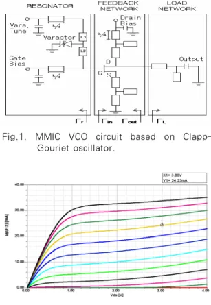
The basic schematic of a Clapp type oscillator is shown in fig.1. Most RF oscillators can be explained as feedback circuits. The magnitude of loop gain to maintain the continuous oscillator condition should be unity, and the phase difference of the loop should be zero. That is,
ΓIN(jw) ΓL(jw)=1 (1) An LC tank is also included to keep a stable frequency. A basic Clapp-Gouriet oscillator consists of aparallel inductance and capacitance,
the LC tank impedance is real, and phase difference is zero when starting oscillation.
Fig.1. MMIC VCO circuit based on Clapp- Gouriet oscillator.
Fig. 2. Reflection coefficient of VCO
The bias condition is chosen asVdd=
3V(Id=24.25mA), Vgg=-0.1V for the oscillator.
The output load impedance is selected for the maximum output power in fig.2.
Oscillation occurs when s11 is greater than 1.
If it is less than 1, a feedback inductance of 0.5nH is added to the open stub as series feedback at the FET Source for the purpose of achieving |Γin|>1. Fig. 3 shows simulation results of reflection coefficient that show on a Smith chart that the magnitude of S11(-1.813+j0.937) is larger than 1[12][13].
The inductance value in the resonant circuit is chosen to set the oscillation frequency of the VCO circuit. The resonance condition for
oscillation is XL(o) = - XIN(o) and the inductance(L1) at 35GHz is chosen as 0.367nH and the inductance(L2) as 0.308nH by the same method in fig. 4.
Fig. 3. Reflection coefficient of VCO
Fig. 4. Circuit of VCO
Fig. 5. Impedance of optimized oscillator
The simulated characteristic impedance is shown in fig. 5. As a result, the oscillation
condition is satisfied so that the real part of impedance is –439 at 35GHz and the imaginary part is almost zero.
To achieve a good output power of the oscillator, the negative resistance looking into the collector of the PHEMT devices is designed to be about three times that of the resistance looking into the output load. That is,
-RL(w)+jXL(w) = -RIN(w)/3-jXIN(w) (2) The results of simulation are shown in fig. 6.
The oscillation frequency is 34.73GHz and the output power is 10.76dBm when the DC bias condition is Vdd=3V (Id=24.25mA), Vgg=-0.1V.
And the harmonic suppression is excellent at more than -30dBc.
Fig. 6. Oscillation frequency characteristics of VCO
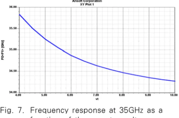
Fig. 7. Frequency response at 35GHz as a function of the varactor voltage
The tunable range of frequency with varactor voltage varying from 4V to 8V is shown in fig.
7. The frequency is tuned from 34.5GHz to 36.5GHz with an approximate bandwidth of 2GHz, and the output power is shown from 8.5GHz to 11.5GHz.
Simulation result with phase noise of -100dBc/Hz at 1MHz offset is shown in fig. 8.
Fig. 8. Simulation result of phase noise
The schematic of the designed circuit is shown infig. 9. The manufacturing uses the 0.15um pHEMT foundry of TRW.
Fig. 9. Schematic of designed MMIC chip
3. Measured Results
3.1 Assembling of MMIC VCO
Kovar is widely used for the carrier in VCO modules with an impedance of 50 ohms. Also, an alumina substrate is applied to the output port of the VCO MMIC. An isolator that has
20dB isolation characteristics is used to minimize the reflection of the VCO output power, and it is assembled with 0.7mm diameter thickness wire bonding for minimizing the transmitting power loss for each of the components in fig. 10.
Fig. 10. Assembled VCO module (Size=12(L)*15(W)*5(H)mm)
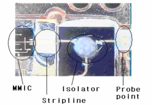
A detailed figure of the VCO moduleis shown in fig. 11 which is assembled with the MMIC, alumina substrate, isolator and probe point.
Fig. 11. Assembling of MMIC and components
3.2 Test Results
VCO test results are shown in fig. 12. The results are very similar to the simulation results, such as a frequency of 34.73GHz and a power of 11.06dBm.
The non-linearity is less than 13% when the voltage range of the varactor varies from 3V to 8V. Thisis shown in fig. 13.
Fig. 12.Characteristics of oscillation frequency
Fig. 13.Frequency and power level by tuning voltage
Test results of the phase noise of – 90.27dBc/Hz at 1MHz offset are shown in fig.
14. These reached the design goal of -100dBc/Hz at 1MHz offset at thebias condition.
Fig. 14. Phase noise photograph of MMIC VCO
The VCO is assembled on the carrier that is fabricated with eutectic and epoxy bonding with no carrier for biasing. Also, 0.7mil wire bonding
and 10mil ribbon bonding are used for assembling the VCO. These assembling techniques require delicate fabrication skills because tolerance error has a significant influence on the system characterization [14].
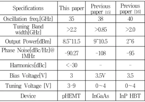
The test results such as output power and bandwidth show a good performance compared with previous results. These test results can be shown in Table 2 [15][16].
Table 2. The tested results compared with previous paper
Specifications This paper Previous paper [15]
Previous paper [16]
Oscillation freq.[GHz] 35 38 40 Tuning Band
width[GHz] >2.2 >0.85 >2.0 Output Power[dBm] 8.5~11.5 9~10.5 2~6 Phase Noise[dBc/Hz]@
1MHz -90.27 -108 -95
Harmonics[dBc] <-30 - -
Bias Voltage[V] 3 3.5V 3.5
Tuning Voltage [V] 3-9 0~4 0~4 Device pHEMT InGaAs InP HBT
4. Conclusion
In this paper, a MMIC VCO for Ka-Band is designed and assembled. It is fabricated by the 0.15um pHEMT foundry of TRW. A Clapp-Gouriet type oscillator is used to provide series feedback in the MMIC VCO for the purpose of high power output and wide tunable bandwidth. The VCO Module is manufactured in a small and integrated size,which is assembled on the carrier using wire & ribbon bonding that hasonly 0.2dB insertion loss. The designed MMIC VCO was assembled as a module for testing and the test results showed a frequency of 35GHz, the tuning bandwidth about 2.2GHz and the output power of 11.5dBm.
Although it was designed for -100dBc/Hz at 1MHz offset, the phase noise was testedat -90dBc/Hz at 1MHz offset. The test results have good performance compared with previous results.
The developed reconfigurable MMIC VCO can be used for target sensing such as wireless communication systems, radar and anti-collision radar for cars. Also, it can be applied to wireless ubiquitous systems.
References
[1] S.A. Hovanessian, "Radar System Design and Analysis," 1984.
[2] Merrill I. Skolinik, "Radar HandbookEd),"
McGraw-Hill Book Co.,1990.
[3] T.Takehana, H.Iwamoto, T.Skamoto, and T.
Nogami, "Millimeter-Wave radars forAutomotive
Use, SAE technical PaperConvergence, " 1988.
[4] Y. Kwon. et al., "Large signal analysis and experimental characteristics of monolithic InP-Based W-band HEMT Oscillator," in 21th European Microwave Conf. Tech Dig., Stuttgart, Germany, Sept. 1991.
[5] H.Wang et al., "Monolothic W-band VCO’s using pseudomorphic AlGaAs/InGaAs/GaAs HEMT’s," in 14th Ann. IEEE GaAs IC Symp.
Dig., Miami, FL. Oct. 1992, pp.47-50.
[6] M. Funabashi et al., "A V-band AlgaAs/InGaAs hetrojunction FET MMIC dielectric oscillator,"
In 16th Annual IEEE GaAs IC Symp. Dig., Philadelphia, PA. Oct. 1994, pp. 30-33.
[7] E Sonmez. et al., "16GHz Integrated Oscillator Design with Active Elements in a Production Ready SiGe HBT MMIC Technology," EUMC, Paris, France, 2-6. Oct. 2000.
[8] Ulrich L Rohde david P. Newkirk,
"RF/Microwave Circuit Design for Wireless Applications," 2000.
[9] John. S. Seybold, "Introduction to RF Propagation," 2005.
[10] Terry Edwords, "Gigahertz and Terahertz technologies for broadband communications"
[11] Andrew Hunter MNZIS, MSc Candidate, "The Road to ubiquitous geographic information systems roam anywhere," Dec. 10-13th, 2000.
[12] Gonzales, "Microwave Transistor amplifiers Analysis and Design," 2nd Edition, 1997.
[13] Minoru Maeda, katsuhiro Kimura,Hiroshi Kodera, "Design and Performance of X-Band Oscillator withSchottky-Gate Field-Effect," IEEE Trans. MicrowaveTech., vol. MTT-23, no. 8, pp.
661-667, Aug. 1975.
[14] Thomas A. Midfod, "The Evolution ofPackage for Monolithic Microwave andMillimeter-Wave Circuits," pp 983-991, Sept. 1995.
[15] A. Kurdoghlian. et al., "38GHz Low Phase Noise CPW Monolithic VCO’s Implemented in Manufacturable AlInAs/InGaAs HBT IC technology," IEEE Trans. Microwavery Tech., pp99-102, 2000.
[16] A. Kurdoghlian.et al., "40GHz Fully Integrated and Differential VCO with Wide Tuning Range in ALLNAS/INGAAS HBT," IEEE Trans.
MicrowaveTech., pp129-132, 2001.
저 자 소 개