FPGA 기반의 갈릴레오 E1 및 E5 신호 처리 구현 및 성능에 관한 연구
** *
정회원 신 천 식 , 이상욱 , 윤동원**, 김재훈*
A Study on the Implementation and Performance Analysis of FPGA Based Galileo E1 and E5 Signal Processing
Cheon Sig Sin*, Sanguk Lee**, Dongweon Yoon* and Jaehoon Kim** Regular Members
요 약
본 논문에서는 위성항법신호감시국에 대한 핵심기술인 FPGA 기반의 위성항법수신기를 구현하여 갈릴레오 E1 및 E5 신호처리 동작검증 및 처리결과를 제시하였다. 성능 검증을 위해 시제품 형태의 위성항법안테나, 112MHz 샘플링 주파수 및 8비트 양자화 레벨을 제공하는 RF/IF 유니트를 이용하여 갈릴레오 시험위성인 지 오베-B(GIOVE-B)로부터 E1 및 E5를 수신하여 이용하였고, 수신된 데이터에 대한 신호처리 수행을 통해, FPGA 기반의 항법수신기 모듈에서 갈릴레오 E1 및 E5 신호가 정상적으로 동작됨을 입증하였다.
Key Words : Global Navigation Satellite System(GNSS)(전역위성항법시스템), Navigation Receiver Unit(위성항 법수신기), GNSS Sensor Station(위성항법신호감시국), GPS and Galileo Combined Receiver(지피 에스/갈릴레오 복합수신기).
ABSTRACT
The key technologies of GNSS receiver for GNSS sensor station are under development as a part of a GNSS ground station in ETRI. This paper presents the GNSS receiver implementation and signal processing result which is implemented based on FPGA to process the Galileo E1 and E5 signal. To verify the working and performance for GNSS receiver which is implemented based on FPGA, live signal received from GIOVE-B which is second test satellite is used. We gather GIOVE-B signal by using prototyping antenna and RF/IF units including IF-component.
To verify Galileo E1 and E5 signal processing function from GIOVE-B, FPGA based signal processing module is implemented as a prototyping hardware board.
I. Introduction
Recently, satellite navigation system becomes the most optimal, widely-used means for providing navigation and positioning services with high precision for all users at any place all the time.
Up to present, the U.S. Global Positioning System(GPS) and the Russian Global Navigation Satellite System(GLONASS) have been built.
Around 2013, the Galileo System which was
planned to build the Galileo System in 1999 would be put into operation. In addition, other countries such as China(COMASS system), India(IRNSS system) and Japan(QZSS system) are also planning to build their own satellite navigation systems which are covered the regional or global.
The positioning, velocity and timing service provided by the satellite navigation systems have been used in many fields. It has great influences on the corresponding industries, technology and people living styles. The satellite navigation has
* 한양대학교 공과대학 전자통신컴퓨터공학부
** 한국전자통신연구원 위성관제·항법연구팀
Eamil ([email protected], [email protected], [email protected], [email protected]
논문번호:논0901-13, 접수일자:2009년 6월 22일, 최종게재논문통보일자 : 2009년 6월 24일
※본 연구는 본 연구는 지식경제부 및 정보통신연구진흥원의 IT신성장동력 핵심기술개발사업의 일환으로 수행하였음. [2007-
become an important infrastructure just like highways, water providing system and electric system. ETRI involved in developing technologies of related with GNSS ground sensor station from 2007 up to 2010. The system configuration which will be researched and developed by ETRI is shown in figure 1. The main purpose of the GNSS ground sensor station is to develop the key technologies such as high precision receiving function of GPS/Galileo combined receiver unit for a global navigation satellite system. The S/W receiver includes the function of baseband technology in the GNSS sensor station.
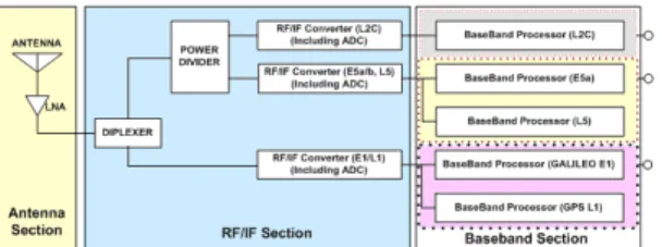
2.1. RF Front End Configuration
For the wide-bandwidth, Galileo E1 and E5 signal processing receiver front end, a low –IF architecture has been chosen. Figure 2 shows the functional block diagram of RF front end.
Automic Clock GPS L1, L2C, L5 signals
GPS Satellites GALILEO Satellites
Galileo E1,and E5a signals
Meteorological Data Measurement Wide Band
Antenna
GPS/Galileo Combined Receiver
Power Supply
Receiver RF/IF Module
Receiver Signal Processing
Module
Fig. 2 Functional Block Diagram of RF Front End
Antenna unit consists of GNSS antenna and low noise amplifier. RF/IF converter unit is composed of diplexer, power divider, and RF/IF converter including AD converter. The antenna and low noise amplifier are operated in the frequency range of 1.16 to 1.61 GHz. For instance, the antenna unit can receive the minimum signal of -130 dBm from GPS navigation satellites. The antenna has been designed to be operated in the hemispherical coverage. The structure of antenna is a kind of conical spiral antenna as shown in figure 3
Fig.1 Block Diagram of GNSS Ground Sensor Station
Fig. 3 Antenna Hardware Configuration
The GNSS receiver can be process wide bandwidth Galileo E1 and E5 signal. All of them are capable of acquiring and tracking four or more satellite signal simultaneously, thus allowing real time positioning with a high performance PC, a prototyping Front End and an analog to digital conversion(ADC) card. The implemented receiver is realized in C code and VHDL code to increase performance for an standard PC running under Windows and FPGA module. Real signals are digitized by a National Instruments(NI) equipment and prototyping ADC card which is connected to a wide bandwidth.
The RF/IF block consists of Diplexer module, power divider module, RF/IF converter module and AD converter module. Each RF/IF converter module for every navigation signal band has been designed with the same configuration. The differences as navigation signal band in the configuration are the image filter, SAW filter, and PLL(Phase Lock Loop).
Ⅱ. GNSS Receiver Configuration
(a) RF/IF Functional Block Diagram
(b)RF/IF Hardware Prototyping Configuration Fig. 4 Block Diagram of Single Band RF/IF Converter
Block
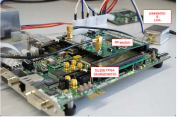
The receiver is based on commercial parts and consists of E5 front-end and ADC Board, FPGA board ML 506, and PC workstation (Fig. 5). The receiver provides raw code, phase measurements and raw navigation messages. The DSP signal acquisition and receiver control is programmed to the PC workstation which also serves as a terminal for displaying of the receiver status. The wide throughput communication between PC workstation and FPGA board is ensured by the Ethernet interface.
RF part
E5 Front-end & ADC
Xilinx kit PCB ML506 8 x E5 correlator 1 x SSB acquisition unit Tracking computer
PC workstation FFT signal acquisition Terminal
PVT (not provided by CTU)
Fig.5 Functional Test configuration for RF/IF Block
2.2. Baseband Configuration
Fig. 6 Block diagram of signal acquisition
The baseband consists of the signal acquisition part and signal tracking part. The mission of signal acquisition is to determine the visible satellite and coarse values of carrier frequency and code phase of the satellite signals. Code phase of first output is the time alignment of the PRN code in order to generate a local PRN code that is perfectly aligned with the incoming signal. Second output parameter is the carrier frequency, which corresponds to the IF. To consider the Doppler effects, the frequency can deviate up to 5kHz in case of the stationary receiver. It is important to
know the carrier frequency of the signal to be able to generate a local carrier signal. The acquisition block consists of the three blocks such as carrier removal, acquisition by FFT and PRN code generator as shown in figure 6 [1].
Tracking mode consists of the carrier tracking and code tracking. The code tracking procedure is required to maintain the very high level of synchronization necessary to determine position accurately. To do this, one must generate an error signal to estimate the phase difference between the PRN code in the received signal and locally generate PRN code. The general signal tracking processing flow is shown in figure 7.
Fig. 7 Block diagram of signal tracking
The tracking is running continuously to follow the changes in frequency as a function of time. If the receiver loses track of a satellite, a new acquisition must be performed for that particular satellite. The sate machine for signal acquisition of receiver is based on the figure 8.
The signal tracking consists in having fixed parameters of loops to use the figure 9. By using the results of code and carrier loop, the bit synchronization is fitted and data are demodulated.
Fig. 8 State machine of signal acquisition
1. Signal Acquisition
The function of signal acquisition is to find a roughly estimate value of the PRN code phase offset and carrier frequency. Signal acquisition is essentially a two-dimensional search process in which replica code and replica carriers are aligned with the received signal. In the method of the signal acquisition, it can largely be divided into three methods with the serial search, parallel frequency space search, and the parallel code space search. It is advantageous to use the parallel code space search algorithm in order to be suitable for the S/W receiver, improve the TTFF, and reduce the computational complexity [2]. The parallel code search algorithm obtains the correlation function value about all combinations between the replica signal samples and the digitized IF signal samples by using DFT. Instead of multiplying the input signal with a PRN code with 4092 for E1 signal and 10230 for E5 signal of different code phases as done in the serial search acquisition method, it is more convenient to make a circular cross correlation between the IF digitized input and local PRN code. The circular cross correlation function between IF signal and local PN code can be written as
Fig. 9 Simple flow diagram of tracking
To extract the navigation data, the C/A code and the carrier wave can be removed from the signal, only leaving the navigation data bits after properly tracking the signal. The value of a data bit is found by taking integration over a navigation bit period of 20 msec. After reading about 30 sec of data, the beginning of a subframe must be found in order to find the time when the data was transmitted from the satellite.
The signal processing board which is based on FPGA(Field Programmable Gate Array) is shown in figure 10.
( * ) ( * )
( ) l( ) IF( ) l( ) IF( ) z k =IDFT R f R⋅ f =IDFT R f R⋅ f ………..(1)
where Rl is discrete Fourier transform of local PN code and is discrete Fourier transform of the IF digitized signal. Fine frequency acquisition block is used to obtain frequency resolution within a few hertz. The carrier value can be found through DFT or FFT and unit of about 10Hz. Since navigation data is 20 ms or 20 C/A code, maximum data length should be 10 ms. In this paper, it will use that a data length of 4 ms for E1 and 1 msec for E5 signal for the acquisition algorithms is applied each other. 4ms corresponds exactly to the length of one complete C/A code, so it simplifies the algorithm. Fig. 11 shows the results of signal acquisition for Galileo E1 signal which described in the code phase and carrier frequency. In this figure, x axis represents the code phase which use the chip as a unit, y axis represents the Doppler frequency which uses the MHz as a unit and z axis represents magnitude which means the peak power of correlation.
Fig. 10 Signal Processing Board Configuration
Ⅲ. Simulation and Test Results
E1 and E5 Signal processing module are responsible for acquiring and tracking GIOVE-B satellites. First, the algorithm performs a search for satellites in view, or, if valid almanac information and approximate receiver position and time are available, estimates which satellites are visible and attempts to acquire them. After acquisition, the code phase and Doppler of each acquired satellite are used to initialize the tracking loops. These loops (carrier and code loops) are updated continuously so that satellite and receiver dynamics can be tracked.
Fig.11 Signal Acquisition Results for Galileo E1
The signal acquisition of the Galileo E5 signal is a key problem in the receiver design. The classical sequential search algorithms widely used on GPS L1 frequency are highly time demanding tasks. The acquisition time of the E5 signal by sequential algorithm is in range of tens minutes, which is fully impractical. The alternative solution of the acquisition problem is a DSP acquisition which is based on parallel computation of the cross correlation function between received signal and replica and its maximum search in a computer or DSP. The DSP acquisition of E5 signal is very computation cost demanding task because of relatively high PRN chip rate, long E5 PRN codes, and required high processing gain.
The proposed acquisition method utilizes only one E5a or E5b signal component because of significant reduction of the sampling frequency of such signal and less memory requirement and lower computation cost.
The algorithm of the signal parameters estimation runs in a PC workstation because of required computation power and memory space.
The first step of the acquisition algorithm is a replica generation and its transform to the frequency domain. As a example, primary code generation algorithms is shown in figure 12.
The order of the codes is reversed to allow usage of convolution instead of correlation. The code length is 10230 bits, therefore it must be resampled to length=18667 according to considered sampling frequency. The code is split to 19 segments. Each of them has length 1024 samples (the last segment is zero-padded to obtain required length).
Each of the segments is zero-padded to double length (2048 samples) and is converted to the frequency domain. The preparation of the replica
read. We can show here the results of the tests of Initial acquisition block which are fully completed.
Fig.12 Algorithm for the generation of the primary code
Fig.13 Functional Block Diagram for Signal Acquisition
The Snapshot acquisition block serves for capture of the received signal snapshots for FFT acquisition purpose. The acquisition is executed on only one signal component (E5a or E5b) of the E5 signal for the sake of reduction of the computation cost and snapshot memory size. The received signalsI_ 8 _ 7+j sQ. _ 8 _ 7 is frequency shifted in order to achieve the fall of appropriate carrier frequency of the selected signal component to the zero frequency. The sampling rate of the signal is reduced by six. The block
The block saves signal sample to the external 32 bit memory of size 216 (64 k) words. The snapshot capture is controlled by the Start_Bool signal and is synchronized to the TIC signal.
When we processed signals received on July, 2008 we obtained correlation function shown on Fig. 14. As shown in figure 14, time offset shown in x axis means the difference value between input signal and replica code and the difference value is located in around 1.8*10^4 samples.
Also on the y axis the correlation peak between input signal and replica signal is shown and the value has an about 8 dB.
Fig.14 Correlation function of the GIOVE-B signal
2. Signal Tracking
Signal tracking is the process that a receiver synchronizes the Galileo and GPS signal.
Tracking module can configure the loop bandwidth, integration time, early-late chip spacing and correlator’s number to use for tracking[4]. Applied parameters such as integration time, discriminator type to get the simulation result are shown in table 1.
Table 1. Simulation Conditions for Signal Tracking Parameter Galileo E1 Galileo E5 Coherent
Integration Time 4 msec 1 msec Loop Type DLL/PLL DLL and PLL DLL Discriminator
Type
Nomalized early minus envelope
Nomalized early minus envelope PLL Discriminator
Type Atan Atan
DLL/PLL Order 2nd/2nd 2nd /2nd DLL/PLL BW 5Hz/15Hz 5Hz/10 Hz
The tracking loops consist of a delay lock loop (DLL) for tracking the code and a phase lock loop (PLL) to track the carrier. The code tracking block of the S/W receiver is implemented using the method of Early-Late code tracking, that involves correlation with three different generated codes known as the early (E), the prompt (P), and the
late (L) codes [5]. To provide an input to the code generator, the outputs of correlators should be combined. To do that, the code phase of the generated PRN code will be properly adjusted.
The input of code generator is computed through normalized early minus late envelope discriminator. The carrier tracking block of the S/W receiver is implemented as a Costas PLL. A PLL measures the carrier phase error and adjusts the frequency of the local oscillator based on that error. The input of local oscillator is computed through arctangent discriminator because of its high accuracy and insensitivity towards navigation bit transitions.
The tracking results for Galileo E1 signal are shown in figure 15. Although in case of Galileo E1 there are existed data channel and pilot channel, only the tracking result of data channel is described.
Fig. 15 Tracking Results of Galileo E1 Signal
3. Testing Result on FPGA Board
The algorithm of signal acquisition and tracking should be porting on FPGA. The porting results of Galileo E5 signal are shown in figure 16.
Fig.16 FPGA porting results of Galileo E5 signal
In figure 16, each paragraph is the decoding data results and means the information as followings;
OUT: TIC { CH No, PRN #, Flag, Pseudorange [msec], Carrier Phase..}
Where, TIC is the reference local time. The sequence inserted into brackets { ... } contain output of n-th receiver channel (see 오류! 참조 원본을 찾을 수 없습니다.). The total number of the channels is given by FPGA configuration.
•TIC: receiver time-base counter. Incrementing rate is 1 250 per a second, period 800 microseconds.
•Stat : status of the channel
Fig.17 Code and Carrier Phase deviation for Galileo E5 signal
In figure 17, blue color means the Giove-A, samples number which is 7,169 and red color means the Giove-B with 7,798 as a samples number.
•satID: satellite identifiers such as Giove-A=51, Giove-B=52
•flags: a hexadecimal number, reserved for
future extension Based on the porting results, we can confirm that the results implemented on the FPGA are the same as those on the c-programming.
•PRG:pseudorange in milliseconds (it increases as the satellite pseudorange is
increased) In case of Galileo E1 signal, the porting results based on signal processing board with FPGA and DSP is shown in figure 18. At that time, we verify the carrier to noise between simulation result with c programming and test result with porting on the FPGA.
•PHASE:carrier phase in cycles (it decreases as the satellite pseudorange is increased)
•DPRG :carrier frequency shift in Hz (positive as the satellite pseudorange is increased)
•POW: signal power or signal to noise ratio (SNR)
•data_E5a-I : sequence of received E5a data bits closed to the quotation marks
•data_E5b-I : sequence of received E5b data bits closed to the quotation marks To get the upper value, the commercial board is used and at that time signal strength for Galileo GIOVE-B is -127 dBm.
At -127 dBm signal strength, Code and carrier phase for Galileo E5 signal are shown in figure 17.
In figure 17, x axis means the sample number of code in upper and lower figure. Also In case of y axis, upper figure means the pseudorange deviation for Giove-A and B satellites and lower figure means code phase deviation for Giove-A and B satellites.
Fig.18 Comparison between C programming result and FPGA processing result
As shown in figure 18, we find the almost same result between c programming result and FGPA processing result. At that time we use the four(4) channel to compare the carrier to noise ration each other. The level of carrier to noise got from simulation and testing is around 37 dB-Hz.
저 자 IV. Conclusions
신 천 식(Cheon Sig Sin) 정회원 In this paper, the wide-band antenna and RF/IF
components and SW signal processing unit to cover the GPS/Galileo signals of GNSS receiver for GNSS sensor station was presented. GNSS receiver architecture and implementation results for the FPGA based signal processing of Galileo E1 channel and E5 channel are presented. By using the FFT algorithm, the signal acquisition algorithm could do the fast and exact signal acquisition with a few data. Moreover, DLL and PLL could be finely tracked by using the fine acquisition. To get the IF sample data, we have to use the RF-IF hardware prototype and receive directly the RF signal from GIOVE-B which is Galileo Test Satellite. The signal processing results by using live GIOVE-B signal were performed successfully by using prototyped antenna, RF/IF, and baseband.
1990년 2월: 한양대학교 전자 공학과 졸업
2000년 2월: 충남대학교 전자 공학과 석사
2005년 3월∼현재: 한양대학 교 전자통신 컴퓨터공학 과박사과정
1990년 2월~현재: 한국전자 통신연구원 책임연구원
<관심분야> 위성항법, 위성항법수신기, 위성통신 위성궤도주파수
이 상 욱(Sanguk Lee) 정회원 1988년 2월: 연세대학교 As a future work, we will make the detailed
design document of GNSS ground sensor station and implement the FPGA based hardware GNSS receiver. It can be used for GNSS sensor station in the future.
천문기상학과 졸업 1991년 3월: Auburn대학교
항공우주공학과 석사 1994년 3월: Auburn대학교 항공우주공학과 박사 1993년 3월∼현재: 한국전자 References
통신연구원책임연구원 [1] Kaplan, Elliot D., “Understanding GPS:
Principles and Applications,” Artech House, 2006
<관심분야> 인공위성시스템, 위성항법
[2] Van Nee, J.R. & Coenen, J.R.M., “New Fast GPS Code-Acquisition Technique Using FFT,”
Electronics Letters, Vol.27.2, Jan., 1991
윤 동 원(Dongweon Yoon) 정회원 1989년 2월: 한양대학교 [3] Cheon Sig SIN, "A Software Receiver
Implemenation for GPS L1 and Galileo E1 Signal", pp. 46-58, Vol 1, ASMS 2008.
전자통신공학과 졸업 1992년 2월: 한양대학교
전자통신공학과 석사 [4] Manandhar, D., Y. Suh, R. Shibasaki, “GPS
Signal Acquisition and Tracking – An Approach towards Development of Software- based GPS Receiver,” Technical Report of IEICE, ITS2004, July 16, 2004
1995년 8월: 한양대학교 전자통신공학과 박사 1995. 3-1997.8 동서대학교
전임강사 [5] K. Borre, D. M. Akos, N. Bertelsen, P. Rinder,
S. H. Jensen, “A Software-Defined GPS and Galileo Receiver,” Birkhauser Boston, 2007
1997.9 -2004.2 대전대학교 부교수
2004. 3 – 현재, 한양대학교 전자통신컴퓨터공학부 교수
<관심분야> 무선통신,이동통신,위성 및우주통신
김 재 훈(Jaehoon Kim) 정회원 2001년 2월: 충북대학교
컴퓨터 공학과 박사 1992년∼1994년:영국 Marta
-Marconi Space OJT 1983년 3월∼현재:한국전자 통신연구원 위성관제 항법연구팀장
<관심분야> 위성관제, 위성항법, 탐색구조시스템