• 검색 결과가 없습니다.

Experimental and Finite Element Analysis of Free Vibration Behaviour of Graphene Oxide Incorporated Carbon Fiber/Epoxy Composite

N/A
N/A
Protected

Academic year: 2021

Share "Experimental and Finite Element Analysis of Free Vibration Behaviour of Graphene Oxide Incorporated Carbon Fiber/Epoxy Composite"

Copied!
6
0
0

로드 중.... (전체 텍스트 보기)

전체 글

(1)

Paper

Experimental and Finite Element Analysis of Free Vibration Behaviour of Graphene Oxide Incorporated Carbon Fiber/Epoxy Composite

Nitai Chandra Adak*, Kamalkishor Janardhanji Uke**, Tapas Kuila* , *** , Pranab Samanta* , *** , Joong Hee Lee****

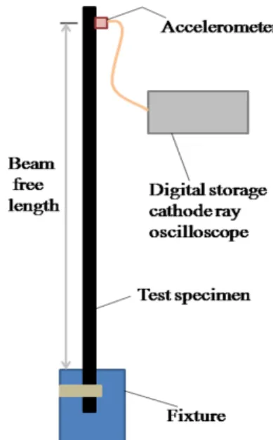
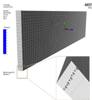
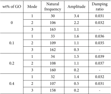
ABSTRACT: In the present study, the effect of GO in damping capacity of CF/epoxy laminates was studied via free vibration analysis. The composite laminates were manufactured by using vacuum assisted resin transfer molding technique. The damping properties of the prepared hybrid composites were determined in terms of natural frequency and damping ratio in free vibration test. The foremost aspire of this investigation was to compare the vibration properties i.e. natural frequency and modal damping of the prepared composites with the numerical results. The numerical study was carried out via FEA using ANSYS

TM

workbench software. The parametric study of the numerical models was also studied considering the beam free length and the beam thickness. It was found that the incorporation of GO enhanced the damping capacity of the composite and the variation of natural frequencies in mode1varied by 2- 5% compared to the experimental study.

Key Words: Graphene, Composite, Vibration study, Numerical analysis

1. INTRODUCTION

The use of carbon fiber (CF)/epoxy composites are grad- ually increasing day by day in different high strength struc- tural applications, especially in automotive and aerospace due to their high specific strength and stiffness [1]. The structure made from CF/epoxy composites like automobiles, space- crafts, military equipment and wind turbine blades frequently suffer from the mechanical vibrations during their regular operations [2]. The structures show premature failure due to fatigue and enhancement of crack propagation speed of micro-cracks present in these structures under vibration. The CF/epoxy composites are brittle in nature and have low damp- ing capacity which sometimes restricts the widespread appli- cations in new areas [3]. A number of techniques have been

applied to progress the damping properties of the fiber rein- forced polymer composites, i.e. introduction of high damping polymer films in prepreg lay-up [4] and addition of hybrid rubber particle in the composites [5]. However, the improve- ment in damping capacity of the composites arising from these techniques is liable for the detritions of mechanical properties.

In the last two decades, with the development of carbonaceous nanofillers i.e. carbon nanotubes (CNTs), multiwall carbon nanotubes (MWCNTs), graphene nanoplatelents (GNPs), graphene oxide (GO) etc and their composites have attracted significant interest to improve the damping characteristics of polymers, particularly epoxy resin, in terms of damping ratio [6] and loss modulus [7]. Among the carbonaceous nanofill- ers, GO has high mechanical strength, large interfacial surface area and different functional groups which helps to interlock

Received 17 October 2018, received in revised form 2 December 2018, accepted 11 December 2018

** *

***

****

Academy of Scientific and Innovative Research (AcSIR), CSIR-CMERI, Campus, Durgapur 713209, India

Condition Monitoring and Structural Analysis Division, Council of Scientific and Industrial Research-Central Mechanical Engineering Research Institute, Durgapur-713209, India

Surface Engineering & Tribology Division, Council of Scientific and Industrial Research-Central Mechanical Engineering Research Institute, Durgapur-713209, India

Advanced Materials Research Institute for BIN Fusion Technology (BK Plus Global, Program), Department of BIN Convergence Technology, Chonbuk National University, Jeonju 54896, Korea

Corresponding authors, Dr. Pranab Samanta (E-mail: [email protected]), Dr. Tapas Kuila (E-mail: [email protected]) and

Prof. Joong Hee Lee (E-mail: [email protected])

(2)

with the polymer segment and helps to improve the mechan- ical properties of the composites [8,9]. With the enhancement of the mechanical properties of the composites, the GO implies a frictional sliding with the epoxy matrix during oscil- lation and cause dissipation of a large amount of energy with a high damping capacity [10]. The ‘‘stick-slip’’ mechanism is also may be responsible for the enhancement of energy dissipation potential of GO based polymer composites [11]. Though a number of research works are available in existing literature depending on the improvement of the mechanical and dynamic mechanical properties of the GO incorporated epoxy nanocomposites or fiber reinforced laminated composites, the works based on the effect of GO on the free vibration of the CF reinforced epoxy laminted composites are rare. Therefore, it is an obvious gap to investigate the effect of GO on the free vibration analysis of the CF/epoxy composites experimentally as well as numerically. The numerical analysis of the free vibration test of GO incorporated CF/epoxy composites will help to avoid the costly experimental study and will improve the design of composite structures by applying some design parameters which is obtained from the parametric numerical study.

Herein, GO incorporated CF/epoxy laminates were man- ufactured by using vacuum assisted resin transfer molding (VARTM) technique. The damping properties of the prepared hybrid composites were determined in terms of natural fre- quency and damping ratio in free vibration test. The foremost aspire of this investigation is to compare the vibration prop- erties i.e. natural frequency and modal damping of the pre- pared composites with the numerical results.

2. MATERIALS AND EXPERIMENTAL

2.1 Materials

Natural graphite flakes are used to produce GO. A plain weave carbon fabric with an areal density of 200 g/m

2

was pur- chased from Flips India Engineering (Mumbai) for reinforce- ment. The low viscosity, liquid modified Bisphenol-A epoxy resin (LAPOX*C-51) and low viscosity modified cycloal- iphatic amine hardener (Lapox AH-428) were procured from Atul Limited (Gujarat, India) to make the matrix system in this study. Natural graphite flakes are bought from Sigma- Aldrich., hydrochloric acid, sulphuric acid, potassium per- manganate and hydrogen peroxide, tetrahydrofuran (THF) are purchased from E-Mark, Mumbai; India. All the chemicals are of analytical grade and used as received without further puri- fication.

2.2 Preparation of composite materials

The GO was prepared from natural graphite flakes accord- ing to the modified Hummers method as reported in our ear- lier works [12]. In order to modify the epoxy resin by introducing the GO nanofiller, the desired amount of nano-

filler first dispersed in THF via sonication for 1 h in a bath sonicator. The dispersal was added with epoxy resin to get concentrations of 0.05, 0.1, 0.2 and 0.4 wt% as compared to the weight of the resin and hardener. The surplus THF was removed from the GO-epoxy blend through evaporation at 80

o

C under reduced pressure for an hour. The suitable amount of hardener poured into the GO-epoxy blend and stirred at 700 rpm for 15 min for homogenization. Finally, the GO- implanted epoxy matrix was obtained to manufacture the hybrid composite after degassing the blend in a vacuum cham- ber for 4 min at room temperature. The composites were pre- pared using the VARTM process. At first, the fabrics were cut into dimension of 14 cm × 25 cm and then placed on a mold- ing tool that was previously coated with the mold release agent to easily remove the prepared composites. The stacking sequence of the lamina was [(0/90)

5

] for the free vibration test.

The thickness of each lamina was 0.4 mm. A peel ply was placed on to the top of the fabric to prevent a complex sep- aration of the bagging film from the prepared composites. A nylon mesh was positioned on the top of the peel ply to make sure the continuous resin transfer in the lateral direction and the inlet of the resin supply is fixed around the fabrics. The vacuum pressure was 0.3 Pa and the resin was cured with the shape of the recital fabrics. The prepared composite plates were post-cured at 85

o

C for 2 h and 120

o

C for 2 h after curing at room temperature for 20 h. Finally, the samples were cut from the panels to conduct mechanical tests.

2.3 Measurements of vibration damping properties The dynamic responses of the composite materials were obtained as a combination of its modes, knowledge of the mode shapes, modal frequencies and damping ratios. Rect- angular specimens of 60 mm wide 4 mm thick and 220 mm

Fig. 1. Schematics of the experimental set-up for free vibration

(3)

long were cut from the CF/epoxy laminate plates for vibration tests according to the ASTM standard E756. The specimens were tested in the free vibration mode and the corresponding configurations are given in Fig. 1. The free beam length is defined as the distance between the clamp and the specimen tip. In the free vibration test, cantilever beam specimens were used with one end clamped and the other end deflected to a desired displacement before release. The resulting vibration response was continuously monitored using the accelerometer (Model: Vib 6.142R, Pruftechnik) attached to the tip of the specimen, which was stored in a digital storage cathode ray oscilloscope (CRO).

The accelerometer was attached over the beam using wax and connected to the Dual Channel Vibration Analyser (Model: VibXpert, Pruftechnik). The accelerometer converted the physical motion given by the exciter to the laminate into an electrical signal. A signal conditioning amplifier used to trans- fer the accelerometer characteristics compatible with the input electronics of the DAQ. The data received was channeled on to the Omnitrend Condition Monitoring Software (VIB 8.981) in the PC via a power adaptor. Two adapters were used, one to receive signal from accelerometer and the other to measure the magnitude of response by the exciter from the laminates. Each vibration or input given with the help of a hammer is picked up by the accelerometer and converted into frequency values in Omnitrend Condition Monitoring Software and displayed in the computer screen.

2.4 Theory

The existence of damping is supportive in many cases.

Damping limits the amplitude of vibration. In any structural application, damping can be introduced to avoid resonance.

One of the methods is selecting structural materials having high internal damping. Laminated composites usually exhibit very high material damping. The damping ratio can be deter- mined from the frequency response curve shown in Fig. 2. In

this method the frequency response graph is portioned into several frequency ranges. Each partitioned frequency range is then considered as the frequency response function of a single degree of freedom. This implies that the frequency response function in each frequency range is dominated by that specific single mode. The peak denotes the resonance point. Thus, the resonance frequencies can be identified as the peaks in Fig. 2.

The damping ratio corresponding to peak i, with resonant fre- quency ω

i

, the model damping ratio can be determined using ξ = (ω

2

− ω

1

)/2ω

n

, where, ω

2

, ω

1

are known as half power points lie either side of the resonant frequency ω

n

[13].

3. FINITE ELEMENT ANALYSIS (FEA)

The free vibration analysis of the prepared composite lam- inates was analyzed numerically via FEA using ANSYS

TM

workbench (Version 16.2) software. To carry out the FEA, the laminate models were considered as orthotropic in nature. The FEA models for the free vibration test are identical to the experimental specimens, and the material properties are given from the experimental tensile test results of the developed GO/

CF/epoxy composites as reported in our previous work [8].

The vales of E

11

, E

22

, G

12

, v

12

are 7.5 GPa, 7.5 GPa, 1.2 GPa and 0.04, respectively. The laminate models are created according to the stacking sequences of the lamina of the prepared com- posite, and the thickness of the each lamina is 0.4 mm. ANSYS Composite Prepost (ACP) is deployed for generating the numerical models. The models are imported into the modal analysis to determine the natural frequency and vibration modes of the numerical models. The parametric study of the composite models was also carried out depending on the length and thickness of the composite laminates. The bound-

Fig. 2. Definition of ω

1

, ω

2

and ω

n

according to the half-band width method

Fig. 3. Numerical model with meshed elements for free vibra-

tion test

(4)

ary conditions were applied to the numerical models accord- ing to the actual free vibration analysis of the composite specimens during the testing. One end of the cantilever spec- imen model is fixed, and the beam free length or the beam thickness was varied as boundary conditions for the free vibra- tion analysis of the numerical models. Fig. 3 shows the mesh- ing models of the free vibration test specimens. The number of elements was 6700 and the number of nodes was 8564. The stacking sequence of the laminas is shown in the rectangular box of Fig. 3.

4. RESULTS AND DISCUSSION

4.1 Modal analysis

The vibration analysis of the prepared CF/epoxy laminated composites were carried out and modal analysis was inves- tigated in detail. In the present analysis, fixed-free end con- ditions were considered. The first three natural frequencies and three mode shapes were determined for all the materials.

The results are shown in Table 1. The excitation was given by using a small hammer and the magnitude of the impact of the hammer was measured piezoelectric force transducer through the adopter connected to the hammer. The force caused by the hammer, was nearly proportional to the mass of the hammer and the impact velocity. The shape of the frequency response was dependent on the mass of the hammer and the stiffness of the material structure. The displacement signal of the lami- nates was received by a light weight accelerometer which was fixed at the free end of the cantilever and at the midpoint in the simply supported beam and the fixed beam. The signal from the transducer was sent to the analyzer via DAQ for sig- nal processing. Fast Fourier Transform (FFT) analyzer was used which received analog voltage signals from a signal con-

ditioning amplifier for computation. The signal analyzed by the analyzer was used to find the natural frequency, damping ratio and mode shapes. OMNITREND Condition Monitoring Software (VIB 8.981) was used to get the frequency response.

This software is generally designed for vibration control and monitoring. The natural frequency and the amplitude were measured directly from the software. The model triggered excitation and the frequency response curve is shown in Fig. 4.

From Table 1 it is understood that the fundamental natural frequencies varies with material. The natural frequency is the function of stiffness of the material and the mass. From the Fig. 4, it is clear that the amplitude of the oscillation decreases with the incorporation of GO in the CF/epoxy composites and enhances the damping capacity of the laminates.

In order to examine the accuracy of the experimental results, FEA was carried out of the composite samples. From the experimental analysis, it was difficult to show the mode shapes of the composite samples. Fig. 5 shows the modal shape of the composite samples. The natural frequencies of the com- posite models were determined from the FEA and it was Table 1. Calculated values of free vibration results of GO incorpo-

rated CF/epoxy composites

wt% of GO Mode Natural

frequency Amplitude Damping ratio

0

1 30 3.4 0.031

2 106 2.2 0.032

3 163 1.1 -

0.1

1 33 1.6 0.036

2 109 1.1 0.035

3 162 0.3 -

0.2

1 34 1.5 0.039

2 108 1.1 0.037

3 160 0.2 -

0.4

1 32 1.4 0.032

2 107 0.5 0.031

3 158 0.2 -

Fig. 4. Exciting frequency response of (a) pure CF/epoxy and (b) 0.1 wt%, (c) 0.2 wt%, (d) 0.4 wt% GO incorporated CF/

epoxy composite

Fig. 5. Mode shapes for (a) mode 1 (b) mode 2 (c) mode 3 of

0.2 wt% GO incorporated CF/epoxy composite

(5)

observed that the differences in mode 1 natural frequency was within 2-5%, but in mode 2 and mode 3 the difference was more than 20%. The shadow rectangular shape signifies the unreformed shape of the models and color areas are the deformed shapes in three different modes.

4.2 Parametric study

The aim of this study is to investigate the changes of natural frequency with the change of the laminate thickness and free beam length of the samples. The change of natural frequency with the beam free length of the prepared samples is shown in Fig. 6(a). From the Fig. 6(a), it is clearly observed that the nat- ural frequency decreases with the increase of the beam length.

The thickness of the composite samples varied from 110- 200 mm and the frequency changes of the composite samples with the length for three different modes were studied com- prehensively. The frequency change for mode 1 is less com- pared to the other modes and with the increase of the mode no, the value of natural frequencies are also increased. The change of the natural frequency of the composite samples is shown in Fig. 6(b) depending on the laminates thickness.

From the Fig. 6(b), it is evident that with the increase the thickness of the composite materials, the value of natural fre-

quencies also increases. The thickness of the composite sam- ples varied from 2-4 mm. For mode 1, the changes of natural frequencies are less compared to the mode 2 and mode 3. The details of the changes of the frequency for each mode of the composite samples considering the beam free length and the composite thickness are summarized in Table 2.

5. CONCLUSIONS

In this study, the free vibration analysis of the prepared GO reinforced CF/epoxy laminated composite was analyzed. The free vibration test indicated that the damping ratio of the GO hybridized CF/epoxy composites increased with increasing the GO loading in the composites. The natural frequency of the prepared composites varied between 30-34 Hz and the damp- ing ratio also varies between 0.03-0.04. From the modal anal- ysis of the composites, it is evident that the mode 1 and mode 2 are prominent and mode 3 is diminishing with the incor- poration of the GO content in the CF/epoxy composites. The oscillation amplitudes of the hybrid composites also decreased with the loading of GO in the CF/epoxy composites.

ACKNOWLEDGEMENT

The authors are thankful to the Director of CSIR-CMERI.

The authors are also thankful to the Council of Scientific and Industrial Research, New Delhi, India, for funding the Fast Track Translational Project (MLP218112).

Fig. 6. Variation of frequencies depending on (a) beam free length and (b) beam thickness of 0.2 wt% GO incorpo- rated CF/epoxy composite

Table 2. Calculated values of frequencies of 0.2 wt% GO incorpo- rated CF/epoxy numerical model

Beam free length

(mm)

Mode No

Natural frequency

(Hz)

Beam thickness

(mm)

Mode No

Natural frequency

(Hz)

110

1 109

2

1 16

2 445 2 104

3 684 3 116

130

1 78

2.8

1 23

2 368 2 145

3 491 3 162

150

1 59

3.2

1 26

2 314 2 166

3 369 3 184

170

1 46

3.6

1 29

2 273 2 187

3 287 3 208

200

1 33

4

1 33

2 208 2 208

3 229 3 229

(6)

REFERENCES

1. Adak, N.C., Chhetri, S., Kuila, T., Murmu, N.C., Samanta, P., and Lee, J.H., “Effects of Hydrazine Reduced Graphene Oxide on the Inter-laminar Fracture Toughness of Woven Carbon Fiber/epoxy Composite”, Composites Part B: Engineering, Vol.

149, 2018, pp. 22-30.

2. Khan, S.U., Li, C.Y., Siddiqui, N.A., and Kim, J.K., “Vibration Damping Characteristics of Carbon Fiber-reinforced Compos- ites Containing Multi-walled Carbon Nanotubes,” Composites Science and Technology, Vol. 171, 2011, pp. 1486-301494.

3. Chandra, R., Singh, S.P., and Gupta, K., “Damping Studies in Fiber-reinforced Composites –a Review”, Composite Structures, Vol. 46, 1999, pp. 41–51.

4. Liao, F.S., Su, A.C., and Hsu, T.C., “Vibration Damping of Inter- leaved Carbon Fiber-epoxy Composite Beams”, Journal of Com- posite Materials, Vol. 28, No. 18, 1994, pp. 1840-1854.

5. Moser, K., and Lumassegger, M., “Increasing the Damping of Flexural Vibration of Laminated FPC Structures by Incorpora- tion of Soft Intermediate Plies with Minimum Reduction of Stiffness”, Composite Structures, Vol. 10, 1988, pp. 321-333.

6. Koratkar, N.A., Wei, B.Q., and Ajayan, P.M., “Carbon Nanotube Films for Damping Applications”, Advanced Materials, Vol. 14, No. 13-14, 2002, pp. 997-1000.

7. Chhetri, S., Adak, N.C., Samanta, P., Mallisetty, P.K., Murmu, N.C., and Kuila, T., “Interface Engineering for the Improve- ment of Mechanical and Thermal Properties of Covalent Func-

tionalized Graphene/epoxy Composites”, Journal of Applied Polymer Science, Vol. 135, No. 15, 2018, pp. 1-10.

8. Adak, N.C., Chhetri, S., Kim, N.H., Murmu, N.C., Samanta, P., and Kuila, T., “Static and Dynamic Mechanical Properties of Graphene Oxide-Incorporated Woven Carbon Fiber/Epoxy Composite”, Journal of Materials Engineering and Performance, Vol. 27, 2018, pp. 1138-1147.

9. Chhetri, S., Samanta, P., Murmu, N.C., Kuila, T., and Lee, J.H.,

“Enhanced Mechanical Properties of Functionalized Graphene Oxide/linear Low Density Polyethylene Composites Prepared by Melt Mixing”, Composite Research, Vol. 29, 2016, pp. 173- 178.

10. Zhou, X., Shin, E., Wang, K.W., and Bakis, C.E., “Interfacial Damping Characteristics of Carbon Nanotube Composites”, Composites Science and Technology, Vol. 64, 2004, pp. 2425- 2437.

11. Rajoria, H., and Jalili, N., “Passive Vibration Damping Enhancement Using Carbon Nanotube-epoxy Reinforced Composites”, Composites Science and Technology, Vol. 65, 2005, pp. 2079-2093.

12. Kuila, T., Bose, S., Khanra, P., Mishra, A.K., Kim, N.H., and Lee, J.H., “A Green Approach for the Reduction of Graphene Oxide by Wild Carrot Root”, Carbon, Vol. 50, No. 3, 2012, pp.

914-921.

13. Bachmann, H., Vibration Problems in Structures, Bulletin

D’Information, Wien, No 209, 1991.

수치

Fig. 1. Schematics of the experimental set-up for free vibration
Fig. 2. Definition of ω 1 , ω 2  and ω n  according to the half-band width method
Fig. 5. Mode shapes for (a) mode 1 (b) mode 2 (c) mode 3 of 0.2 wt% GO incorporated CF/epoxy composite
Table 2. Calculated values of frequencies of 0.2 wt% GO incorpo- incorpo-rated CF/epoxy numerical model

참조

관련 문서

The proposal of the cell theory as the birth of contemporary cell biology Microscopic studies of plant tissues by Schleiden and of animal tissues by Microscopic studies of

웹 표준을 지원하는 플랫폼에서 큰 수정없이 실행 가능함 패키징을 통해 다양한 기기를 위한 앱을 작성할 수 있음 네이티브 앱과

_____ culture appears to be attractive (도시의) to the

It considers the energy use of the different components that are involved in the distribution and viewing of video content: data centres and content delivery networks

After first field tests, we expect electric passenger drones or eVTOL aircraft (short for electric vertical take-off and landing) to start providing commercial mobility

1 John Owen, Justification by Faith Alone, in The Works of John Owen, ed. John Bolt, trans. Scott Clark, "Do This and Live: Christ's Active Obedience as the

In this study, the finite element analysis was used to predict and obtain the material properties of the carbon fibers and the resin even if the carbon fiber laminate and the

the Smart City Platform The City Integrated Operation Center.