Influence of Pad-Pivot Friction on the Performance of Tilting-Pad Journal Bearing Sung-Gi Kim, Kyung-Woong Kim and Hyun-Cheon Ha
패드와 피봇 사이의 마찰이 틸팅패드 저널베어링에 미치는 영향
김성기† · 김경웅* · 하현천**
Key Words : Pad-pivot Friction(패드-피봇 마찰), Tiling-pad Journal Bearing(틸팅패드 저널베어링) Abstract
The need for developing a mathematical model for pad-pivot friction in tilting pad journal bearings has been well-recognized, since previous experimental work about the performances of the bearings hypothesized that the friction in the bearings is closely related to their performances. Especially, the sliding friction between pad and pivot in the ball and socket type of the bearings can influence the performance of the bearing. We propose a mathematical model for pad-pivot friction in the ball and socket type, which considers the geometrics of the pad and pivot of the bearings, by assuming the sliding friction in the ball and socket bearing as Coulomb friction. By utilizing the proposed model for pad-pivot friction, we show the analysis of Reynolds equation and energy equation, which explain the thermo-hydrodynamic characteristics of tilting pad journal bearings, by taking into account the turbulence and inlet pressure building as well. The results of the study show that the performance of titling-pad journal bearings can be greatly influenced by the pad-pivot friction.
In particular, we have shown that the analysis of the pad-pivot friction is useful to explain the static journal loci and the dynamic characteristics of the ball and socket type of the bearings. Furthermore, for a given operating condition, we can obtain various equilibrium states which satisfy the static equilibrium conditions, by considering the pad-pivot friction.
V 저널 표면의 속도 [m/sec]
기호설명 w 하중 [N]
X, Y 좌표 [m]
γ 패드각 [rad]
h 유막 두께 [m]
η 절대점도 [Pa•sec]
p 유막 압력 [Pa]
ω 각속도 [rad/sec] t 시간 [sec]
Ip 패드의 관성모멘트 [kg•m2]
x, z 좌표 [m]
L 베어링 폭 [m]
Mf 패드-피봇 마찰에 의한 패드모멘트[N•m] 1. Introduction
Mp 유막에 의한 패드모멘트 [N•m]
R 베어링 반경 [mm]
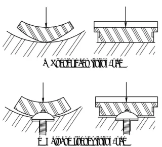
There are several types of tilting pad journal bearings, including the rocker back type and the ball and socket type, where the two types of tilting pads and their corresponding bearings are depicted in Fig. 1 and in Fig.
2 respectively. The friction in the rocker back type has the rolling contact between the pad and the pivot, where severe wear can occur due to the load concentrated on
Tm 유막 온도 [°C]
Ts 윤활유의 공급온도 [°C]
† KAIST
E-mail : [email protected]
TEL : (042)869-3286 FAX : (042)869-3210 * KAIST
** (주) Turbo Link
wp wp
(a) Rocker back tilting-pad
wp
wp
(b) Ball and socket tilting-pad
Fig. 1 Two types of tilting-pad
the contact, thereby enlarging bearing clearance and reducing the working life of the bearing. Contrarily, the friction of the ball and socket type has the sliding contact between the two. In practice, the ball and socket type of tilting-pad journal bearing is utilized in precision machines because of its longer working life than that of the rocker back type, although it is more expensive and requires larger space than the rocker back type.
Wygant et al. [1,2] performed experiments on the performances of tilting pad journal bearings, such as journal loci and dynamic coefficients of the bearings.
They observed that the journal equilibrium locations and the dynamic coefficients of the two types were different from those of each other, while Pettinato and Choudhury [3,4] reported more detailed differences between the two types. Based on the observation, they hypothesized that pad-pivot friction makes the difference, since the coefficient of friction for sliding in the ball and socket type is two orders of magnitude larger than that for rolling in the rocker back type.
These experimental approaches, however, did not prove the hypothesis theoretically nor explain side-effects of the friction.
As a theoretical approach, we propose a mathematical model for the friction in the ball and socket type of tilting pad journal bearings, which considers the geometrics of the pad and pivot of the bearings, by assuming the sliding friction in the ball and socket bearing as Coulomb friction. By utilizing the proposed model for pad-pivot friction, we show the analysis of Reynolds equation and energy equation, which explain the thermo-hydrodynamic characteristics of tilting pad journal bearings, by taking into account the turbulence and inlet pressure building as well.
(a) w/o pad-pivot friction (b) w/ pad-pivot friction
Fig. 2 Schematic diagrams of tilting-pad journal bearings
2. Method
2.1 Object
Tilting pad journal bearings are depicted in Fig. 2, where Fig. 2 (a) shows a schematic figure of the tilting- pad journal bearing without pad-pivot friction and where Fig. 2 (b) shows a schematic figure of the tilting- pad journal bearing with pad-pivot friction. The specifications of the bearings and oil which are analyzed in this paper are listed in Table 1.
2.2 Pad-pivot friction model
The model of the pad-pivot friction which is occurred at ball and socket tilting-pad is depicted in Fig. 3. The friction force (Ff) is the product of the normal force (wp) by the coefficient of friction (µ) between pad and pivot.
The normal force (wp) indicates the force that is exerted
Table 1 The specifications of the bearing and oil
Bearing diameter D 300.92 mm
Bearing length L 149.5 mm
Bearing clearance Cp 0.458 mm
Pad arc β 52o, 75o
Pivot position βp/β 0.5
*Pivot radius rf 50 mm
*Pad-pivot friction coeff. µ 0.1, 0.5
Pad thickness tp 24 mm
Preload d 0.05 mm
Oil density(40℃) ρs 845 kg/m3 Oil viscosity(40℃) ηs 0.027 Pa·sec
T-ηcoefficient α 0.00332/℃
Oil specific heat c 1966 J/kg℃
* means parameters used in only the case of Fig. 2 (b).
2.3 Static analysis on the pad by the lubricant film. The friction force
generates a friction moment (Mf) which exerts influences on a tilting angle of the pad. The friction moment can be modeled with two cases. If the pad is tilting, we assume that the magnitude of the friction moment keeps a constant value (µrfwp) and that the direction is opposite to tilting direction. Otherwise, it is assumed that the friction moment is calculated as a function of pivot moment by the lubricant film (Mp), as shown in Fig. 3 (b). In this model, it is assumed that the centre of action for the friction moment (Mf) is the centre of ball pivot. Numerical formulas for the friction moment are equations (1) and (2) below.
The Reynolds equation for turbulent flow with the variation of oil viscosity is derived into the equation (3) by employing the thin film assumption of classic lubrication theory and Constantinescue’s model [5]. The equation is solved in order to obtain distribution of film pressure.
x h V z p G h z x p G h
x x z ∂
= ∂
∂
∂
∂ + ∂
∂
∂
∂
∂
2
3 3
η
η (3)
The pressure on the boundary of pad except pad inlet is ambient pressure, while the inlet pressure occurring at leading edge is calculated by the model of Kim and Kim [6]. If there is a negative pressure, the Reynolds’
boundary condition is used for solving the equation.
Furthermore, turbulent coefficients Gx, Gz and τc are adopted from Constantinescue’s model [5] and the transition range used in this paper is adopted from Bouard et al. [7]. A pad angle is determined when total moment exerted on the pad is zero as the following equation (4):
p f p p
f rw
M
M =−M µ at γ&≠0 (1)
≥
−
<
−
=
p f p p
f p p
p f p p
f r w at M r w
M M
w r M at M
M µ µ
µ ,
, at γ&=0 (2)
This model is very simple but can explain main effect of friction moment on the performances of tilting-pad journal bearings. It can also achieve the purposes of this study which are to verify the friction hypothesis and to explain additional effects of pad-pivot friction with a numerical method. We will discuss about its achievements in the following sections, while leaving the study on more complicate and precise friction model as future work.
=0 +
= p f
t M M
M (4)
Equation (4) means that the pad angle is determined when |Mp| is lower than |µrfwp| because Mf is expressed by equation (2) in static analysis. Thus, possible solutions for the pad angle are innumerable.
Energy equation for the turbulent flow can be simplified as in the equation (5), which is used to obtain distribution of film temperature.
∂ + ∂
∂ + ∂
−
=
∂
∂
∂
− ∂
∂
∂
∂
− ∂
2 2
3 2
1 2
z G p x G p c ch
V
z T z G p x T x G p h V
z x
c
m z m x
ρ ρ ητ η
(5)
It is assumed that the inlet temperature at the leading edge of each pad is equal to the mixing temperature [8], while the other interfaces are insulated.
(a) Pad-pivot friction
2.4 Transient analysis
In order to obtain trajectories of journal and pads, motion equations for journal and pads are solved. The motion equation of a pad is defined as follows:
(b) Friction moment
( p f)
p
M I M +
= 1
γ&& (6) Fig. 3 Pad-pivot friction model
Angular acceleration of pad (γ&&) is calculated not from Mp alone but from total moment (Mp+Mf) exerted on the pad. Mf is expressed in equations (1) and (2).
1.0 0.8 0.6 0.4 0.2 0.0 -0.2 -0.4 -0.6 -0.8 -1.0
-1.0 -0.8 -0.6 -0.4 -0.2 0.0 0.2 0.4 0.6 0.8 1.0
Tilting-Pad w/ Friction Tilting-Pad w/o Friction Fixed-Pad
Y/Cp
X/Cp For a tilting-pad journal bearing working in the
transient state, pressure and temperature distribution in the lubricant film are determined by the transient Reynolds equation (7) and transient energy equation (8).
t h x h V z p G h z x p G h
x x z ∂
+∂
∂
= ∂
∂
∂
∂ + ∂
∂
∂
∂
∂
2
3 3
η
η (7)
∂ + ∂
∂ + ∂
−
=
∂
∂
∂
− ∂
∂
∂
∂
− ∂
∂ +
∂
2 2
3 2 2
1 2
z G p x G p c ch
V
z T z G p x T x G p h
V t T h
z x
c
m z m x m
ρ ρ ητ
η η
(8)
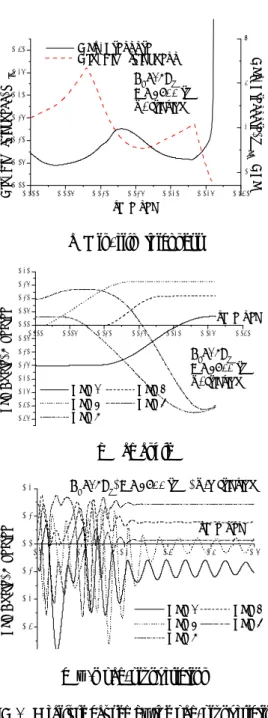
(a) Journal loci
180 200 220 240 260
0.0 0.2 0.4 0.6 0.8 1.0
4-Pad Tilting-pad Bearing (center pivot, same size 4-pads) No.3 Pad Data
θ , degree
Tilting-Pad w/ Friction Tilting-Pad w/o Friction Fixed-Pad
Pressure, p (MPa)
The boundary conditions of equations (7) and (8) are the same as that of static analysis. In order to determine the initial conditions, it is assumed that the bearing has been working in a steady state.
In order to simulate a transient motion, it is assumed that the bearing undergoes a pulse shock. The pulse shock is defined with amplitude (Ad), direction (φd) and interval (td), as shown in equations (9) and (10).
d d
d d d d
d d
d d d
t t t at
t t A Y A
t t t A X A
>
− +
=
− +
=
, sin 4 ) sin(2
2 2
cos 4 ) sin(2
2 2
π φ π φ
(9) (b) Pressure distribution (w=10kN)
180 200 220 240 260
0.00 0.04 0.08 0.12 0.16 0.20 0.24 0.28 0.32 0.36 0.40
θ , degree
4-Pad Tilting-pad Bearing (center pivot, same size 4-pads) No.3 Pad Data
Tilting-Pad w/ Friction Tilting-Pad w/o Friction Fixed-Pad
Film thickness, h (mm)
td
t at Y
X= =0, ≤ (10)
3. Results and discussion
3.1 Static results and verification of the friction hypothesis
(c) Film thickness distribution (w=10kN)
The proposed method gives a clue to the suggestion that the pad-pivot friction exerts significant influences on the performance of tilting-pad journal bearing. Figure 4 (a) shows journal loci of the bearings which are working in steady state. In the case of tilting-pad journal bearings without pad-pivot friction, the journal loci of a bearing form into a straight line path. This is the well-known behavior of a tilting-pad journal bearing. In the case of tilting-pad journal bearings with pad-pivot friction, however, the journal loci of a bearing form into a curved path as in the case of the fixed pad. This result is similar to the experimental result of Wygant et al, which verifies the friction hypothesis. The result also implies that cross couple coefficients of stiffness and damping are non-zero in the case of tilting-pad journal bearings with pad-pivot
Fig. 4 Journal loci, pressure and film thickness distribution (ω=2250 rpm)
friction. The curve of journal loci for a tilting-pad journal bearing with pad-pivot friction is not smooth because each point indicates a case among innumerous solutions.
Figures 4 (b) and (c) indicate the distributions of film pressure and film thickness for a pad, respectively. These figures show that the pad-pivot friction exerts significant influences on the distributions of film pressure and film thickness. These differences among the curves in Fig. 4 (b) and (c) are inferable from the differences among the curves in Fig. 4 (a).
3.3 The influences of static friction
1.0 0.8 0.6 0.4 0.2 0.0 -0.2 -0.4 -0.6 -0.8 -1.0
-1.0 -0.8 -0.6 -0.4 -0.2 0.0 0.2 0.4 0.6 0.8 1.0 Ad=15Cp ω = 3000 rpm w/o friction Y/Cp
X/Cp
Figure 6 shows various journal trajectories after pulse shocks. In this figure, the differences among trajectories are caused by various pulse directions. The black rectangles in the figures indicate initial equilibrium positions before the shocks and the black circles indicate equilibrium positions after pulse shocks. As the figure shows, final equilibrium positions are various. The reason is that static friction can have various magnitudes.
The static friction varies the equilibrium positions of pads and journal. The equilibrium positions are dependent on journal paths.
(a) w/o pad-pivot friction
1.0 0.8 0.6 0.4 0.2 0.0 -0.2 -0.4 -0.6 -0.8 -1.0
-1.0 -0.8 -0.6 -0.4 -0.2 0.0 0.2 0.4 0.6 0.8 1.0 Ad=15Cp
ω = 3000 rpm w/ friction
Y/Cp
X/Cp
Occasionally, pad-pivot friction can cause a bearing failure. Figure 7 (a) shows that a bearing failure occurs at t=0.026. At the moment of bearing failure, the minimum thickness of film is 0.000568 mm, which is small enough to judge that the bearing failure occurs, because the minimum thickness is lower than 10-5 × bearing diameter, that is, the order of surface roughness. The direct cause of this failure is that the pad-pivot friction greatly enlarges the angle of the fourth pad in Fig. 7 (b). In the same working condition, however, the tilting-pad journal bearing without pad-pivot friction works without a failure as shown in Fig. 7 (c). This means that pad-pivot friction causes an inappropriate tilting of pad, thereby inducing a failure. Figure 7 (c) also shows that the first and the fifth pads are steadily vibrating during the simulation, which are self-excited vibrations under statically unloaded conditions.
(b) w/ pad-pivot friction
1.0 0.8 0.6 0.4 0.2 0.0 -0.2 -0.4 -0.6 -0.8 -1.0
-1.0 -0.8 -0.6 -0.4 -0.2 0.0 0.2 0.4 0.6 0.8 1.0 Ad=15Cp ω = 3000 rpm Fixed Pad
Y/Cp
X/Cp
3.4 Friction force as a cause of failure
(c) fixed pad
1.0 0.8 0.6 0.4 0.2 0.0 -0.2 -0.4 -0.6 -0.8 -1.0
-1.0 -0.8 -0.6 -0.4 -0.2 0.0 0.2 0.4 0.6 0.8 1.0
φd= 0o Y/Cp
X/Cp
1.0 0.8 0.6 0.4 0.2 0.0 -0.2 -0.4 -0.6 -0.8 -1.0
-1.0 -0.8 -0.6 -0.4 -0.2 0.0 0.2 0.4 0.6 0.8 1.0
φd= 135o Y/Cp
X/Cp
Fig. 5 Journal trajectories (ω=3000 rpm, w=10kN)
3.2 Trajectories of journal and transient performances
Figure 5 compares journal trajectories for three kinds of bearings each of which undergoes a pulse shock (Amplitude=15Cp, Direction=225°, Interval=0.1s). The moving direction of journal for tilting-pad journal bearing without pad-pivot friction almost coincides with the pulse direction. On the other hand, the journal trajectory for the tilting-pad journal bearings with the pad-pivot friction displays a circular motion as in the case of the fixed pad. This means that the pad-pivot friction raises a circular motion of journal and that an instability phenomenon may occur in the case of tilting- pad journal bearing with pad-pivot friction.
1.0 0.8 0.6 0.4 0.2 0.0 -0.2 -0.4 -0.6 -0.8 -1.0
-1.0 -0.8 -0.6 -0.4 -0.2 0.0 0.2 0.4 0.6 0.8 1.0
φd= 180o Y/Cp
X/Cp
1.0 0.8 0.6 0.4 0.2 0.0 -0.2 -0.4 -0.6 -0.8 -1.0
-1.0 -0.8 -0.6 -0.4 -0.2 0.0 0.2 0.4 0.6 0.8 1.0
φd= 225o Y/Cp
X/Cp
Fig. 6 Various equilibrium locations (ω=2250 rpm, w=10kN)
0.000 0.005 0.010 0.015 0.020 0.025 0.030 0.00
0.05 0.10 0.15 0.20 0.25
0.30 maxMax. Pressure, p (MPa)
Min. Film thickness Ad=15Cp ω = 3900 rpm w/ friction
Min. Film thickness, hmin (mm)
time(sec)
0 2 4 6
Max. Pressure
3. The pad-pivot friction causes a circular transient motion of journal, which means that the oil whirl instability may occur for the tilting-pad journal bearing with the pad-pivot friction.
4. The static friction varies the equilibrium position of journal and the equilibrium position is dependent on the journal path.
5. The pad-pivot friction exerts meaningful influences on tilting of pad and, thus, it can induce a bearing failure.
References
(a) Min. film thickness
(1) Wygant, K. D., Flack, R. D. and Barrett, L. E., 1999,
“Influence of pad pivot friction on tilting-pad journal bearing measurements – Part I: Static operating conditions,” STLE Tribol. Trans., Vol. 42, No. 1, pp.
210~215.
0.000 0.005 0.010 0.015 0.020 0.025 0.030
-0.35 -0.30 -0.25 -0.20 -0.15 -0.10 -0.05 0.00 0.05 0.10 0.15 0.20
Ad=15Cp ω = 3900 rpm w/ friction
Pad Angle, γ (degree)
time(sec)
Pad 1 Pad 2 Pad 3 Pad 4 Pad 5
(2) Wygant, K. D., Flack, R. D. and Barrett, L. E., 1999,
“Influence of pad pivot friction on tilting-pad journal bearing measurements – Part II: Dynamic coefficients,” STLE Tribol. Trans., Vol. 42, No. 1, pp.
250~256.
(3) Pettinato, B. C. and De Choudhury, P., 1999, “Test Results of key and spherical pivot five-shoe tilt pad journal bearings-Part I: Performance measurement,”
STLE Tribol. Trans., Vol. 42, No. 3, pp. 541~547.
(b) Pad angle
0.0 0.1 0.2 0.3 0.4 0.5
-0.3 -0.2 -0.1 0.0 0.1
0.2 Ad=15Cp, ω = 3900 rpm, w/o friction
Pad Angle,γ (degree) time(sec) Pad 1 Pad 2 Pad 3 Pad 4 Pad 5
(4) Pettinato, B. C. and De Choudhury, P., 1999, “Test Results of key and spherical pivot five-shoe tilt pad journal bearings-Part II: Dynamic measurements,”
STLE Tribol. Trans., Vol. 42, No. 3, pp. 675~680.
(5) Constantinescu, V. N., 1973, “Basic Relationships in Turbulent Lubrication and Their Extension to Include Thermal Effects,” ASME J. Lub. Technol., Vol. 95, No.
2, pp. 147~154.
(6) Kim, J. S. and Kim, K. W., 2002, “A Study on the Inlet Pressure Build-Up at Bearing Entrance,” ASME J.
Tribol., Vol. 124, No. 3, pp. 506~514.
(c) w/o pad-pivot friction
(7) Bouard, L., Fillon, M. and Frene, J., 1996,
“Comparison between three turbulent models application to thermohydrodynamic performances of tilting-pad journal bearings,” Tribol. Int., Vol. 29, No.
1, pp. 11~18.
Fig. 7 A failure caused by the pad-pivot friction (ω=3900 rpm, w=10kN)
(8) Ha, H. C., 2001, “Preload effects of a guide bearing on the metal temperature and the shaft vibration,”
ASME J. Tribol., Vol. 123, No. 1, pp. 144~150.
4. Conclusion
This study suggests an analysis model for the pad- pivot friction and analyzes the static and transient bearing performance by using this model. The main findings obtained from the analysis are as follows:
1. The journal loci form into a curved path for the tilting-pad journal bearing with the pad-pivot friction.
This directly supports the friction hypothesis.
2. The pad-pivot friction exerts significant influences on the pressure distribution and film thickness distribution.