Experimental Study of Solid-Liquid Two-Phase Flow in Hydraulic Pumping System of 30m High
Dong-Kil Lee
1), Chi-Ho Yoon
2)*and Won-Mo Sung
3)30m 급 육상 수력펌핑 양광시스템에서의 고-액 2상 유동실험 연구
이동길․윤치호*․성원모
요 약 : 양광시스템은 심해저 광물자원 개발의 성패를 좌우하는 중요한 요소이다.한국지질자원연구원(KIGAM) 에서는 지금까지 양광시스템 개발연구를 수행해오고 있으며 최근에는 30 m 급 육상 양광시험시스템을 구축하였 다.본 연구는 양광관내에서 고-액 유동특성을 규명하고 향후 실해역 채광시스템의 설계자료를 획득하기 위해 수력펌핑양광실험을 수행하였다. 기수행된 소규모 수력펌핑양광실험 결과에 기초하여 30 m 급 육상 수력펌핑 양광시스템이 설계되었다.본 연구에서 수행된 고-액 2상 유동실험은 실제 망간단괴와 동일한 밀도를 가진 직경 20 mm의 모조단괴가 직경 100 mm의 양광관내를 물과 함께 유동할 때 최대 유속은 5 m/sec, 최대 고체체적점유율 은 20%의 조건에서 수행되었다.본 실험으로부터 양광관 내에서의 고체체적점유율과 유동특성 간의 관계를 해석 하였다.본 연구결과는 향후 수행될 근해역 채광실험과 실해역 채광시스템의 설계자료로 이용될 것이다.
주요어 : 수력펌핑양광, 망간단괴, 2상 유동
Abstract : The lifting technology plays a key role in the success of deep-sea mineral development. KIGAM (Korea Institute of Geoscience and Mineral Resources) has striven to develop it, and recently performed 30meter scale on-land lifting experiments. In the study, the hydraulic pumping test has been conducted to understand the flow characteristics of solid-liquid mixture in a lifting pipe and to acquire the design data for real offshore test that will be performed in the future. Firstly, an on-land hydraulic pumping test system of 30 meters in height was designed on the basis of the results in the small scale hydraulic pumping test previously performed. In the experiment of this study, we performed solid-liquid two phase flow tests on the condition that the maximum flow velocity was 5 m/sec and maximum solid volume fraction was 20 %,where lifting pipes were 100 mm in diameter together with 20 mm synthetic manganese nodules of the same density asthe real ones. From the tests we could analyze the relationship between solid volume fraction and flow characteristics in pipes. The results of this study will be used as a basis for the off-shore mining field experiments in the near future and for the design of the deep-sea mining system.
Key words : Hydraulic pumping, Manganese nodule, Two phase flow Vol. 43, No. 2 (2006) pp. 128-133
INTRODUCTION
Hydraulic pumping system is based on two-phase lifting technology, by which manganese nodules can be transportedfrom the seafloor to the mining ship. Most
of the system is located under the sea level, which demands its stability and durability more than anything else because of the difficulty in repair. Also, economic recovery of the manganese nodules requires stable operating conditions and optimum power prediction of the lifting pump.
There have been considerable studies on the hydr- aulic transportation of a two-phase mixture. Kitahara et al.(1985) made synthetic nodules and performed flow tests using various kinds of solid materials up to 42 mm in diameter. Sumardi and Chung(1996) and Chung 2006년 1월 19일 접수, 2006년 4월 3일 채택
1) 한양대학교 공과대학 지구시스템공학 박사과정 2) 한국지질자원연구원 지반안전연구부
3) 한양대학교 공과대학 지구시스템공학 교수
*Corresponding Author(윤치호) E-mail; [email protected]
Address; Gajeong-dong, Yuseong-gu, Daejeon, 305-350, Korea
연구논문
et al.(1998)performed vertical flow experiments to understand flow characteristics using PVC pipes of 2.54 cm in diameter. Xia et al.(1997) performed solid-liquid flow tests to predict and optimize the hydraulic pumping parameters for the development of commercial mining system.
KIGAM developed a simulation model to design a hydraulic pump lifting system for its development and application to deep sea environments of 5,000 meter deep(Yoon et al., 1998 Yoon et al., 1999) and acq- uired basic data from 4.3 meter-scale hydraulic pumping experiments(Yoon et al., 1999). For the application to a sea site, however, it is needed to verify the system in the expanded scale. Therefore, we desi- gned a pilot system on land and installed 30-meter high hydraulic pumping system, which enabled us to analyze the two-phase flow in detail.
KIGAM had performed the preliminary experiments below 10% of discharged solid volume fraction(Yoon et al., 2003). In this study, the hydraulic pumping test has been conducted up to 20% of discharged solid volume fraction and comparedthe results with that of the simulation model.
HYDRAULIC GRADIENT OF TWO-PHASE FLOW
The total hydraulic gradient of the mixture, HT, can be defined as the total hydraulic head per unit length of the pipe as in Eq. (1)(Chung et al., 1998).
L
T Lg
H P
ρ
∆
= ∆
(1)
where, ∆P is the pressure drop measured from pressure gauges attached to upper and lower part of the vertical pipe. And, ∆L, g and ρLdenote the distance between the gauges, gravitational acceleration and density of water, respectively.
The frictional hydraulic gradient, Hm, can be expre- ssed as in Eq. (2)(Sumardi and Chung, 1996).
−
−
= 1
L S S T
m H E
H ρ
ρ
(2)
where,
E
S and ρS are in-situ solid volume fraction and density of solid particle, respectively.The in-situ solid volume fraction, Es, is generally larger than the discharged solid volume fraction, Cs, due to the gravitational force. Volumetric equilibrium between solid particles and water can be expressed as in Eq. (3)(Newitt et al., 1961).
+
−
+
−
−
= S
C V S
S V S
S
ES VM M M S
2 2
2 1/2
(3)
where,
V
M is superficial mixture velocity and the average slip velocity between solid and liquid, S, can be expressed as Eq. (4) in terms of the terminal settling velocity of solid particles, Vo, and the in-situ volume fraction of solid, Es(Govier and Aziz, 1972).
E S V
S O
= −
1 (4)
The discharged solid volume fraction, Cs, is defined by the sum of superficial volumetric flow rate of solid (
Q
SS) and superficial volumetric flow rate of liquid (Q
SL).Q Q C Q
SL SS S= +SS
(5)
EXPERIMENTAL SYSTEM AND PROCEDURES
Design of the system
The experimental setup is similar to that of the previous small-scale two-phase flow apparatus(Yoon et al., 1999). A schematic diagram of the hydraulic pumping system, which is designed to simulate the lifting process for deep-sea manganese nodules, is shown in Fig. 1. The diameter of the vertical pipe was
100 mm and designed to ensure the complete flow movement of up to23.6 m in height, where the measurement interval is 15.5 m with a pressure gauge.
A transparent acryl pipe of 1 m longis attached to the lifting pipe in the level of second floor so that the flow pattern of the solid-liquid two-phase mixturecan be observed. Solid-water mixture is pumped vertically upward through the pipe by a centrifugal pump. Sy- nthetic nodules of 20 mm in diameter were manu- factured using fly ash. Table 1 shows the shape index
and density of the artificial manganese nodules.
There are two pressure tap points on the lifting pipe as shown in Fig. 1. The length of the measuring part of the pipe is 15.5 m. The maximum valueof pressure transmitters is up to 10 bar. For the measurement of solid-water mass flow rates, a flowmeter was used, which was combined with a low level gamma ray density sensor in one package in pipe of 10.16 cm in diameter. The measured mass flow rates of solid and water were compared with the weight by load cells and Fig. 1. Schematic diagram of the hydraulic pumping system of 30 m high.
the instrument has been calibrated.
The data acquisition system consists of sensors, PLC(Programmable Logical Controller), software and PC for monitoring, controlling and storing data. RS- 232 port is used to communicate with PLC. The system acquires all data from pressure gauge, flowmeter, densitometer, pump inverter and level meter, and also controlspump inverter and several valves by Windows- based graphical user interface(GUI) software.
Experimental procedure
The experiments were carried out through the following steps. First, let the lifting pipe be filled with water so that the water head can be situated at the top of the pipe. This means the experimental condition is similar to that of the sea water level. Second, preli- minary experiments are performed to understand the characteristics of a lifting pump. Mass flow rate and velocity according to the pump's output are measured using only water to verify the linear relationship and understand the pump characteristics. Finally, two-phase experiments are performed by changing the total flow rate and solid volume fraction.
RESULTS AND DISCUSSION
The experimental variables are the injection volume fraction and flow velocity of the artificial nodules in the vertical pipe. The measuring variables include pressure drop, superficial volume flow rate, mass flow rate of the solid and fluid, and density of the mixture.
The calculated variables are discharged volume frac- tion, volume fraction in the pipe, pressure gradient, and hydraulic gradient. The experimental results have been compared with the prediction model(Yoon et al., 1998).
The hydraulic gradient of water single-phase flow As a preliminary test before two-phase experiments,
experiments on the hydraulic gradient of clear water have been carried out. The predicted hydraulic gradient of the solid line and experimental results versus fluid velocity waspresented in Fig. 2. As shown in the figure, the hydraulic gradient in this study shows the almost identical tendency with the prediction model.
Table 1. Properties of Synthetic nodules
δ, roundness 1.0>δ>0.75 ζ, flatness 1.0>ζ>0.83 ρ, density 2,140 kg/m3
0 1 2 3 4 5
Velocity of clear water (m/sec) 0
0.1 0.2 0.3
Total hydraulic gradient (m/m water)
Fig. 2. Hydraulic gradient as a function of flow rate of clear water flow.
0 1 2 3 4 5
Superficial mixture velocity (m/sec) 0
0.2 0.4 0.6 0.8
Total hydraulic gradient (m/m water)
Cs = 0%
Cs = 5%
Cs = 10%
Cs = 15%
Cs = 20%
Fig. 3. Total hydraulic gradient as a function of superficial mixture velocity.
The total hydraulic gradient of solid-liquid mixtures Figure 3 shows the total hydraulic gradients of solid-liquid two phase mixtures according to the superficial mixture velocity in the pipe of 100 mm in diameter. It is shown that the total hydraulic gradient increases with the increase in the volume fraction of synthetic nodule. Also, in terms of the superficial mixture velocity, pressure drop increases along the increase in the discharged volume concentration of solid particles. That is becausethe hydrostatic pressure and frictional effect increase when the supply of solid particles increases. From the results, it is consistently observed that the hydraulic gradient increases gradually with the increase of the discharged volume fraction of solid particles. For higher volume fraction, the hy- draulic gradient of two-phase mixtureincreases due to the friction between the wall and solids or amo- ngsolids. The results of experiments and simulation shows good agreement, but simulation results are slightly higher than experimentalvalues.
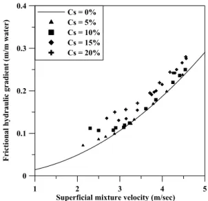
The frictional hydraulic gradient of the solid-liquid mixture Figure 4 illustrates the effects of friction excluding those of gravitationof the solid particles to understand the frictional hydraulic gradient of two-phase flows. On the whole, the hydraulic gradient curve of water is
steeper than that of mixturesbecause the frictional hydraulic gradient of mixtures increases as the super- ficial mixture velocity decreases. On the other hand, as the mixture velocity increases, it becomes closer to the hydraulic gradient of water because the synthetic nodules tend to move towards the pipe center.
CONCLUSIONS
Flow experimental system with an overall vertical height 30 m was designed and constructed to analyze the factors affecting the flow characteristics of a two- phase solid-liquid mixture in the vertical pipe. In those experiments, the maximum superficial mixture velocity and discharged solid volume fraction were 5 m/sec and 20 %, respectively. And diameters of lifting pipe and synthetic nodules of the same density with the real onesare 100 mm and 20 mm. The results of this study will be of help to estimatingthe specifications of hyd- raulic lifting system in the future. From the experi- ments, the following conclusions were drawn:
(1) In the case of a single-phase flow test, the calculated hydraulic gradient shows an almost ide- ntical tendency with the experimental values.
(2) Pressure drop and hydraulic gradient increase with the discharged volume fraction of the solid particle increases. For higher volume fraction of solid particles, the hydraulic gradient of a solid-liquid two-phase mixture increases due to the increase of the additional friction loss between the pipe wall and mixture.
(3) From the experiments for hydraulic gradient of the two-phase mixture in the hydraulic pumping system, it was shown that the hydraulic gradient increases with the increase of the solid fraction and the solid particles moved to the center of the pipe in the case of high fluid velocity, thus the effects of friction loss on the mixture flow was reduced. And the results of the prediction model up to 20%
volumefraction have the similar tendency with the experimental results.
ACKNOWLEDGEMENTS
The authors express appreciation to the Ministry of
1 2 3 4 5
Superficial mixture velocity (m/sec) 0
0.1 0.2 0.3 0.4
Frictional hydraulic gradient (m/m water)
Cs = 0%
Cs = 5%
Cs = 10%
Cs = 15%
Cs = 20%
Fig. 4. Frictional hydraulic gradient as a function of superficial mixture velocity.
Maritime Affairs and Fisheries(MOMAF) of Korea for their full support in this study.
REFERENCES
Chung, J.S., Yarim,G. And Savasci, H., 1998, “Shape Effect of Solids on Pressure Drop in a 2-Phase Vertically Upward Transport: Silica Sands and Spherical Beads,”
Proc. of the 8th International Offshore and Polar Engi- neering Conference, Montreal, Canada, pp. 58- 65.
Govier, G.W. and Aziz, K., 1972, The Flow of Complex Mixtures in Pipes, Van Nostrand Reinhold Company, New York.
Kitahara, R., T. Saito, T. Yamazaki, and T. Usami, 1985,
“Vertical Hydraulic Transportation of Large Solid Materials,” Mining and safety, Vol. 31, No. 3, pp. 34-45.
Newitt, D.M., Richardson, J.F. and Gliddon, B.J., 1961,
“Hydraulic Conveying of Solids in Vertical Pipes,” Inst.
Chem.Engrs., Vol. 39, pp. 93-99.
Richardson, J.F. and Zaki, W.M., 1954, “Sedimentation and fluidisation: Part I,” Trans. Inst. Chem. Engrs., Vol. 32, pp. 35-53.
Sumardi, B.D. and Chung, J.S., 1996, “Measurements of Vertically Upward 2-Phase Flows of Silica Sands in a Pipe,” Proc. of the 4th Pacific/Asia Offshore Mechanics Symposium, Pusan, Korea, pp. 1-8.
Wilson, K.C., Addie, G.R., Sellgren, A. and Clift, A., 1997, Slurry Transport Using Centrifugal Pumps, Blackie Aca- demic & Professional.
Xia, J., Zou, L.X.W., Tang, D., Huang, J. and Wang, S., 1997, “Studies on Reasonable Hydraulic Lifting Parame- ters of Manganese Nodules,” Proc. of the 2nd ISOPE Ocean Mining Symposium, Seoul, Korea, pp. 112-116.
Yoon, C.H., Kim, I.K., Kwon, K.S. and Kwon, O.K., 1998,
“The Numerical Analysis of Particle Flow Patterns in Pipe for Hydraulic Pumping System in Deep-sea Mang- anese Nodules,” Journal of The Korean Institute of Mineral and Energy Resources Engineers, Vol. 35, No.
2, pp. 157-164.
Yoon, C.H., Kim, I.K., Kwon, K.S. and Kwon, O.K., 1999,
“Analysis of Unsteady State Flow Mechanism in Pipe for Hydraulic Pumping System in Deep-Sea Manganese Nodules,” Journal of The Korean Institute of Mineral and Energy Resources Engineers, Vol. 36, No. 1, pp. 33-41.
Yoon, C.H., Kim, I.K., Kwon, K.S., Kwon, S.K., Kang, J.S., Kwon, O.K. and Seo, C.W., 1999, “An experimental study on the flow characteristics of solid-liquid two- phase mixture in a vertical tube,” the 3rd ISOPE Ocean Mining Symposium, pp. 43-48.
Yoon, C.H., Lee, D.K., Park, Y.C. and Kwon, S.K., 2003,
“Design and Test of Hydraulic Pumping System with 30 Height Scale,” Proc. of the 14th International Offshore and Polar Engineering Conference, pp. 61-65.
이 동 길 윤 치 호
1999년 세명대학교 자원공학과 공학사 2001년 한양대학교 지구환경시스템공학 과 공학석사
2001년 한양대학교 지구환경시스템공학 과 박사과정
1982년 한양대학교 자원공학과 공학사 1988년 한양대학교 자원공학과 공학석사 1995년 한양대학교 자원공학과 공학박사
현재 한양대학교 공과대학 지구시스템공학 박사과정 (E-mail; [email protected])
현재 한국지질자원연구원 지반안전연구부 부장 (E-mail; [email protected])
성 원 모
1979년 한양대학교 자원공학과 공학사 1983년 미국 펜실베니아 주립대학교, 석유공 학 석사
1986년 미국 펜실베니아 주립대학교, 석유공 학 박사
현재 한양대학교 공과대학 지구시스템공학 교수 (E-mail; [email protected])