2상 흐름계에서 유로설계에 따른 전해조 분리판의 전산모사 연구
조현학
․장봉재*․송주영†창원대학교 공과대학 화공시스템공학과
*EM Korea (주)
(2010년 9월 14일 접수 ; 2010년 12월 8일 채택)
A study on the channel design of bipolar plate of electrolytic cell by flow dynamic simulation in the two phase flow system
Hyeon-Hak Jo․Bong-Jae Jang*․Ju-Yeong Song†
†
Department of Chemical Engineering, Changwon National University, Changwon, Gyeongnam, 641-773, Korea
*
EMKorea Ltd. Ungnam-dong, Changwon, Gyeongnam, Korea (Received September 14, 2010 ; Accepted December 8, 2010)
Abstract : This study is focused on the channel design of bipolar plate in the electrode of hydrogen gas generator. The characteristics of hydrogen gas generation was studied in view of efficiency of hydrogen gas generation rate and a tendency of gas flow through the riv design of electrode. Since the flow rate and flow pattern of generated gas in the two phase flow system are the most crucial in determining the efficiency of hydrogen gas generator, we adopted the commercial analytical program of COMSOL MultiphysicsTM to calculate the theoretical flow rate of hydrogen gas from the outlet of gas generator and flow pattern of two phase fluid in the electrode. In this study, liquid electrolyte flows into the bipolar plate and decomposed into gas phase, two phase flow simulation is applied to measure the efficiency of hydrogen gas generation.
Keywords ; Bipolar plate, Simulation, COMSOL Multiphysics, Two phase, Hydrogen
1. 서 론
본 연구는 미래의 중요한 에너지원으로 주목 받고 있는 수소의 생산방법으로 친환경적이고 무한의 에너지원인 태양광을 이용하여 전기를 생산한 후 그 전기로 물을 전기분해 하여 수소
✝
주저자 (E-mail : [email protected])
를 얻는 장치인 수전해 장치에 관한 연구로, 그 중에서도 수전해장치의 수소 생산에 중요한 부 분인 전해조(electrolytic cell)의 단위 전기분해 셀내에서의 분리판의 유로설계에 관한 연구이 다. 일반적인 물을 이용한 전기분해 장치에서 모듈설계는 여러 인자에 의해 영향을 받을 수 있겠지만 구조에 의한 영향을 크게 받을 수 있 다. 이러한 영향들에 의해 전기분해 효율의 감
소 등 수소생산의 저해 요소가 발생하게 된다.
이 전산모사는 전해조 내의 단위 전기분해 셀 내에서의 분리판으로 들어오는 전해액을 분리 판 내에서 유동을 균일하게 분포시키고 gas의 흐름을 원활하게해주는 분리판의 유로설계에 관한 것이다. 분리판에 유입되는 전해액의 유속 은 5 L/h로 하였으며, 분리판의 원형판에 위치 한 격자들의 형태와 위치를 변화시키면서 분리 판의 유로설계를 하여 전해액이 들어왔을 때 분리판에서 기체(수소)의 유속과 생성량이 어떻 게 변화하는지 전산모사를 통해 알아보았다. 분 리판의 전산모사에 사용된 것은 다중물리현상 프로그램인 COMSOL multiphysicsTM이다. 액 체상태인 전해액이 분리판으로 들어가 기체(수 소)가 생성되기 때문에 2상 흐름계로 전산모사 하였다. 그 결과 단순 전산모사로는 정확히 어 떤 유로설계일 때 더 좋은 수소생산효율을 보 일 것으로 정확히 단정 지을 수 없기에 전해액 의 유속이 5 L/h로 했을때에 이론적으로는 1,730 cm3/s의 가스발생량이 생겨야 하는데 oulet 부분의 특정 위치에 유속을 평균유량으로 계산한 결과 격자의 유로설계에 따라 다른 기 체유량을 나타내었다.
2. 실험장치 및 방법 2.1. 전해조 원리
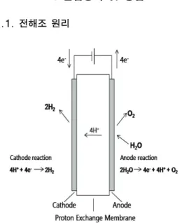
Fig. 1. Principle of proton exchange membrane.
본 연구의 전산모사에 사용된 분리판은 고체 고분자전해(Polymer Electrolysis Membrane, PEM)형 수전해장치의 구성부분이며, PEM형 수전해장치의 원리도는 Fig.1과 같다[2]. 물이 양극으로 공급되면 양극에서는 물이 분해되어 산소와 전하이동체인 수소이온, 전자가 생성된 다. 수소이온은 PEM내에서 surfonic acid 그룹 의 고정이온에서 인접한 다른 고정 이온그룹으 로 이동하여 음극으로 이동한다. 음극으로 이동 한 수소이온은 전기화학적으로 전자와 결합하 여 수소분자(H2)가 된다.
2.2. 분리판의 모델링
본 연구에서는 PEM형 수전해장치의 분리판 을 모델로 전산모사를 하고, 전해조의 수소 생 산 효율을 높이기 위해 전기분해 셀 내의 분리 판에서의 유량 흐름을 균일하게 분포되게 하기 위하여 최적화된 유로설계를 하는데 목적을 두 었다[4].
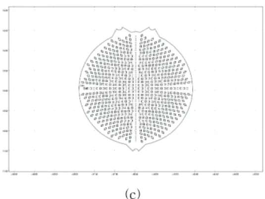
분리판을 모델링 하기 위해 제작된 전해조 분리판을 CAD program (autocad® 2002)을 통 해 도면화 하고(Fig. 3(a)~(c)), 도면화된 2차원 적인 모델을 전산모사 하기 위해 다중물리현상 해석 program인 COMSOL MultiphysicsTM (ver. 3.5a)을 이용하였다[3]. 단위 전기분해 셀 내에 전해액이 공급되었을 때 분리판의 모든 부분에서 유량의 흐름을 일정하게 유지되도록 하기 위하여 격자의 위치와 형태를 변화시키면 서 유로설계를 하고, 유로설계에 따라 2상 흐름 계로 전산모사를 수행하였다[6]. 2상 흐름계로 분리판의 전산모사를 수행했을 때의 조건들은 table 1과 같으며 전산모사를 할 전해조의 상태 는 정상상태일 때를 고려했으므로 초기조건은 설정하지 않았다[4, 5].
Table 1. Simulation conditions of the bipolar plate by two-phase flow
Density(kg/m3) 1280(300 K) 1260(325 K)
Viscosity(kg/m・s) 1.2x 10⁻¹ (300 K)
1.5 x 10⁻¹ (325 K)
Velocity 5 L/h
Effective density
gas (kg/L) 0.000075
또한 모델링 된 분리판 중 격자의 간격을 4 mm인 것을 제작하여 실제 수소발생장치를 만 들어 수소발생량을 체크하여 전산모사 결과와 비교하였다. 분리판을 제작 하여 구성한 전해조 의 모습은 Fig. 2와 같다.
Fig. 2. Electrolytic cell is configured to produce bipolar plate.
(a)
(b)
(c)
Fig. 3. Schematics of the bipolar plate designed by various array of grid (a)~(c).
3. 지배방정식
이 전산모사에 사용되어진 시뮬레이션 프로 그램인 COMSOL MultiphysicsTM에는 여러 가 지 모듈이 있는데 본 연구의 전산모사에서는 화학공학모듈을 사용하였다[8, 9].
3.1 2상 흐름계
단일상으로 전산모사를 수행하여 분리판의 최적의 격자간의 간격과 유속을 찾은 다음 2상 흐름계로 전산모사 하였다[7, 10]. 여기서 2상 흐름계. 즉 two-phase는 액체와 기체이다. 2상 흐름계에 사용되어진 모듈은 화학공학모듈에서 the bubble flow model을 사용하였다. 사용되어 진 지배방정식은 Euler - Euler 방정식이 사용 되었다[1].
∙ ∇
∇ ∇ ∙
∇
∇
∇ ∙
= denote velocity (m/s)
= pressure (Pa) = phase volume fraction (m
3/m3) = density (kg/m
3) g = gravity vector (m/s2)F = any additional volume fraction (N/m3)
= dynamic viscosity of the liquid (Pa·s)
= turbulent viscosity (Pa·s) = quantities related to the liquid and the gas phase
4. 결과 및 고찰
분리판에서는 전해액이 들어가 물이 전기분 해되어 수소가 생성되어 빠져나오게 되는데 one-phase 즉, 단일상으로는 유체의 흐름은 알 수 있어도 생성되는 수소기체의 현상을 알아 볼 수 없기 때문에 단일상으로 얻어진 최적화 결과를 토대로 분리판에 유입되는 전해액의 유 속을 5 L/h로 일정하게 하고, 격자의 형태와 위 치를 다르게 하여 분리판에 배치시킨 유로설계 를 하여 기체유량을 알아 보았다. 2상 흐름계에 서는 inlet 부분은 전해액이 들어가는 조건을 주고 outlet 부분에서는 액체(전해액)는 나오지 않고 기체가 나오는 조건을 주었다.
Fig. 4. Outlet of bipolar plate selection of specific point(black points) by average flow.
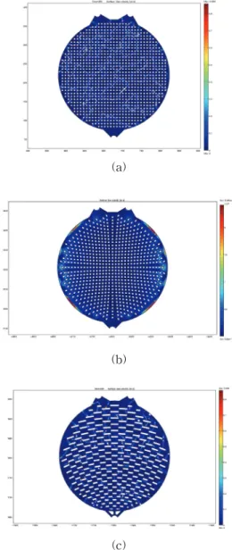
전산모사 결과는 Fig. 5 (a)~(c)와 같다. 전 사모사를 통해 나온 현상만 보았을 때는 정확 히 어떤 분리판의 유로설계에서 효율이 좋다고 판단내리기가 어려운 부분이 있었다. 분리판에 서의 2상 흐름계로 전산모사 결과의 효율을 좀 더 정확히 알아보기 위하여 기체(수소)가 나오 는 outlet 부분을 확대하여 특정지점 100 군데 의 유속을 확인하여 평균선속도를 구한 다음, outlet 부분의 단면적을 곱하여 평균유량을 구 해서 유로설계에 따른 효율을 비교하였다.
Outlet의 포인트 지점은 Fig. 4와 같다. 계산한 결과 전해액의 유입속도가 5 L/h이며 outlet 부
분 단면적은 19.625 cm2으로 단위 전기분해 셀 내의 분리판으로 전해액이 들어갈 때 이론적인 가스 발생량은 1,730 cm3/s 가 나와야 하며 Fig. 5(a)~(c)의 계산결과는 table 2와 같다.
(a)
(b)
(c)
Fig. 5. Simulation results of the bipolar plate by channel design in two phase flow (a)~(c). Electrolyte inflow rate 5 L/h.
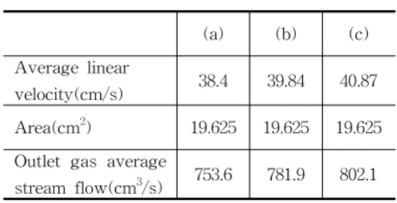
Table 2. Outlet gas average stream flow of Fig. 5(a)~(c)
(a) (b) (c)
Average linear
velocity(cm/s) 38.4 39.84 40.87
Area(cm
2) 19.625 19.625 19.625
Outlet gas average
stream flow(cm
3/s) 753.6 781.9 802.1
그리고 이 전산모사를 토대로 Fig. 4의 (a)의 분리판을 실제로 제작한 다음 단위 전기분해셀 의 2cell을 1set로 전해조를 구성하여 수소발생 장치에서 나오는 실제 수소발생량과 전산모사 에서 나온 수소발생량의 차이를 비교하였다. 수 소발생량의 측정에는 M.F.M(Mass Flow Meter)을 이용하였다. 실제 제작되어진 수소발 생장치의 수소발생량은 Fig. 6와 같다. Fig. 5의 (a)의 전산모사 결과 수소발생량은 753.6 cm3/s 이 나왔지만, 실제 전산모사한 분리판을 제작, 단위전기분해셀을 2cell - 1set로 하여 수소발 생량을 M.F.M으로 측정한 결과 전산모사 결과 보다는 낮은 발생량을 보였다. 전해조는 분리판 뿐만이 아니라 다른 구성요소들의 채결에 따라 효율이 달라질 수 있기에 이러한 차이가 발생 하였다고 예상되며, Fig. 5의 (b)와 (c)의 평균 유량 계산 결과가 (a)보다는 좋고, one-phase로 전산모사를 하였을 때 유량의 흐름이 좋은 결 과를 보였기에 분리판 (b)와 (c)를 실제로 제작 하여 전해조를 구성하여 테스트를 해본다면 더 좋은 결과를 얻을 수 있을 것으로 예상된다.
Fig. 6. Production of hydrogen by bipolar plate(grid distance 4mm).
5. 결 론
수전해장치의 전해조의 한 부분인 단위 전기 분해셀의 분리판에서의 유동분포를 고르게 하 기 위하여 전해액의 유속을 5 L/h로 일정하게 하고 격자의 형태와 위치를 다르게 하여 유로 설계를 하였다[11].
Two-phase 모듈을 선택하여 전산모사를 한 결과 각각 다른 기체(수소)의 유속, 분포를 나 타내었다. 액체(전해액)가 inlet 부분으로 유입 되어 분리판에서 반응을 하여 outlet 부분으로 기체가 나오는 two-phase, 즉 2상 흐름계이기 때문에 단순 전산모사로는 어떤 유로설계가 효 율이 좋은지 판단내리기 어려운 부분이 있다 [12]. 그래서 분리판의 outlet 부분의 평균선속 도를 구하여 단면적을 곱하여 평균유량을 계산 한 결과, 본 연구의 유로설계 Fig. 5(a)~(c)에서 각각 753.6 cm3/s, 781.9 cm3/s, 802.1 cm3/s의 가스 발생량을 나타내었다. 이중에서 (a)의 분 리판을 제작하여 전해조를 구성하여 실제 수소 발생량과 전산모사의 결과를 비교한 결과 (a)의 전산모사 결과인 평균유량 753.6 cm3/s보다 낮 은 500 cm3/s대의 수소발생량을 보였다. 다른 (b)나 (c)의 전산모사 결과가 (a)보다는 더 높은 평균유량을 보였고 유량의 흐름도 좋기에 이를 실제로 제작하여 테스트를 하면 더 좋은 결과 를 보일 것으로 예상된다. 또한 좀 더 다양한 격자의 모양과 조건들을 가지고 유로설계를 한 다면 수소생산 효율을 더 높일 수 있는 결과를 얻을 수 있을 것이다.
감사의 글
본 과제는 지식경제부의 출연금으로 수행한 지역전략기획기술개발사업의 연구결과입니다.
참고문헌
1. J. O. Wilkes, "Fluid Mechanics for Chemical Engineers“, 214, (2008).
2. S. S. Kang, "Expandable electrolyte cell", Korea patent, No. 0511155 (2005).
3. I. S, Laitinen, T. Juha and Tanttu,
"FEM Modeling of an Industrial Scale
Electrolysis Cell", Excerpt from the Proceedings of the 2006 Nordic COMSOL Conference, (2006).
4. D. Sark, V. S. Annaland, M. Kuipers, and J.A.M., "Effect of fluidization conditions on the membrane permeation rate in a membrane assisted fluidized bed",
J.
Chem. Eng., 96, 125–131 (2003).
5. H. H. Jo, S. H. Lee, B. J. Jang and J. Y.
Song, "A study on the bipolar plate of electrolytic cell of hydrogen gas generation system by numerical system",
J. Kor. Oil Chem. Soc., 27(1), 61 (2010)
6. A. Li, C. J. Lim, T. Boyd and J. R,Grace, "Simulation of autothermal reforming in a staged-separation membrane reactor for pure hydrogen production", Can. J. Chem. Eng., 86, 387 (2008).
7. A. M. Dehkordi and M. Memari,
"Compartment model for steam reforming of methane in a membrane-assisted bubbling fluidized-bed reactor", Int. J.
Hydrogen Energy, 34, 1275 (2009).
8. M. Horio, C. Y. ,Wen, "An assessment of fluidized-bed modeling",
A.I.Ch.E.
Symp. Ser., 73, 9–21 (1977).
9. J. R. Grace, R. Clift, "On the two-phase theory of fluidization", Chem. Eng. Sci., 29, 327–334 (1974).
10. J. C. R. Turner, "On bubble flow in liquids and fluidised beds", Chem. Eng.
Sci., 21, 971–974 (1966).
11. J. Nie, Y. Chen, S. Cohen, B. D. Carter and R. F. Boehm, "Numerical and experimental study of three-dimensional fluid flow in the bipolar plate of a PEM electrolysis cell",
Int. J. Thermal Sciences, 48(10), 1914 (2009).
12. J. Nie and Y. Chen, "Numerical modeling of three-dimensional two-phase gas-liquid flow in the flow field plate of a PEM electrolysis cell",