Wideband Flat Optical Frequency Comb Generated from a Semiconductor Based 10 GHz Mode-Locked
Laser with Intra-cavity Fabry-Perot Etalon
Daniel E. Leaird*, Andrew M. Weiner*, Dongsun Seo**★
Abstract
We report stable, wideband, flat-topped, 10 GHz optical frequency comb generation from a semiconductor-based mode-locked ring laser with an intra-cavity high finesse Fabry-Perot etalon. We demonstrate a stable 10 GHz comb with greater than 200 lines within a spectral power variation below 1 dB, which is the largest value obtained from a similar mode-locked laser in our knowledge. Greater than 20 dB of the spectral peak to deep ratio at 0.02 nm resolution, ∼92 femtosecond timing jitter over 1 kHz to 1 MHz range, and non-averaged time traces of pulses confirm very stable optical frequency comb lines.
Key words : Optical frequency comb, optical pulses, mode-locked laser, semiconductor optical amplifier, Fabry-Perot etalon
Ⅰ. Introduction
Wideband, flat optical frequency comb lines at fixed frequencies are very attractive for many applications, such as high capacity WDM communications [1], arbitrary waveform generation [2], optical code division multiple access [3], microwave photonic filters [4], etc. Pulse compression [5] and super continuum spectrum generation [6] to achieve such wideband comb have been applied and showed good results. However, they are indirect methods requiring separate pulse sources and their spectral flatness was not so
* School of Electrical & Computer Engineering, Purdue University, W. Lafayette, IN 47907, USA email: [email protected], [email protected]
**★ Dept. of Electronics, Myongji University, Yongin, Kyonggido 449-728, Korea
email: [email protected], +82-31-330-6369
※ This work was supported by 2013 Research Fund of MyongJi University.
Manuscript received Dec. 02, 2013; revised Feb. 05;
accepted Feb. 05, 2014 .
good.
Recently, two of direct generation methods have been attracted research interests; sideband generation by phase/intensity modulation of continuous wave laser [7,8] and a semiconductor- based mode-locked laser (SB-MLL) with an intra-cavity Fabry-Perot etalon (FPE) [9,10].
Weiner's group reported 38 lines of a 10 GHz optical frequency comb within 1 dB power variation based on the former method [7], and Delfyett's group reported ∼100 lines of a 10 GHz comb using the later method [10]. The former requires stable CW laser and sophisticated phase and intensity modulations, where as the later has relatively simple structure based on an active mode-locking.
Here we use the later method.
For stable mode-locked operation, the SB-MLL with an FPE should satisfy following conditions [10]; (i) the mode-locked pulse repetition rate equals an integer multiple of the laser cavity resonance frequency, (ii) the free spectral range (FSR) of the FPE exactly equals the pulse repetition rate, and (iii) all of the optical comb frequencies match with the FPE transmission peaks. Any mismatching the conditions induces
de-stabilization of the mode-locking due to high loss [10]. Even small amount of mismatching induces the gain modulations of individual modes determined by the FPE-TX curve, resulting in reduced number of optical comb lines (i.e., bandwidth). Significant efforts have been focused to lock optical comb frequencies to the FPE transmission (TX) peaks (in a sense, conditions (i) and (ii) become a subset of condition (iii)).
Techniques for precise FPE-FSR measurement [11]
and very fine cavity length control [10] have been developed. Here we discuss conceptually how the matching condition between the selected super-mode frequencies and FPE-TX peaks affects the mode-locked laser bandwidth. Then we show broadband stable optical frequency comb lines with 10 GHz spacing. We achieve greater than 200 comb lines spaced 10 GHz within 1 dB power variation.
In our knowledge, this is the largest number of flat-topped comb lines obtained from a similar 10 GHz mode-locked laser.
Ⅱ. Matching Between Optical Frequencies and FPE-TX Peaks To achieve wideband, stable comb generation from a SB-MLL, the matching between optical comb frequencies and FPE-TX peaks is essential.
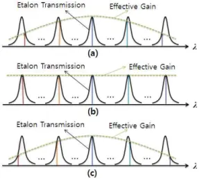
First, the mode-locking frequency should exactly equal to the FPE-FSR. We measured the FSR of the FPE applying the similar method reported in [11]. The measured FSR of the FPE was 9.99577 GHz. When the laser operates at a frequency detuned from the FSR reduces the bandwidth of the mode-locked laser as depicted schematically in Fig. 1. When the mode-locking frequency (i.e., mode-spacing) is smaller (a) or larger (c) than the FPE-FSR, the effective mode gain determined by the FPE-TX curve will be suppressed at shorter and longer wavelengths. This reduces bandwidth of the mode-locked laser output. However, by deliberately tuning the peak of the effective gain curve, we could achieve wavelength tuning of the frequency comb [12]. When the mode-locking frequency is exactly equal to the FPE-FSR, the effective mode gain is not affected (becomes flat)
by the FPE-TX curve, as shown in Fig. 1(b). In this case, the mode-locked laser output shows the broadest bandwidth, as we report here.
Fig. 1. Optical mode gain modulation by the FPE-TX curve .
Fig. 2. Amplitude of the envelope modulated signal as a function of optical frequency.
Fig. 2 shows conceptually how we can get error signal indicating the frequency difference between a lasing mode optical frequency and an FPE-TX peak. Let's assume that we apply a phase modulation (PM) signal to the FPE. The arrows with same color show the instantaneous frequency deviation range by the PM. Then we examine the envelope modulation characteristics of the FPE transmitted signal. Firstly, when the optical frequency is smaller than the FPE-TX peak (dotted red arrows), the FPE acts like a high pass filter;
the FPE passed signal is envelope modulated at the
PM frequency by suppressing the low frequency components and by enhancing the high frequency components. Secondly, when the optical frequency is larger than the FPE-TX peak (dashed green arrows), the FPE acts like a low pass filter; the FPE passed signal is envelope modulated similarly as the first case, but the phase is reversed.
Thirdly, when the optical frequency is coincide with the FPE-TX peak red (solid black arrows), the FPE acts like a bandpass filter; the FPE passed signal is envelope modulated at the twice of the PM frequency by suppressing low and high frequencies and by enhancing the center frequency.
Therefore, if we monitor the PM frequency component from the envelope detected signal, we will get an error signal curve as a function of optical frequency as shown in Fig. 2, which corresponding to the first derivative of the FPE-TX peak. We can use the reflected light from the FPE, then the phase of the error signal is reversed.
In our experiments we modulate a PM modulator at a much larger frequency than the FPE-TX bandwidth and use a reflected signal. The shape of the error signal is still similar to that shown in Fig. 2, but shows large flat-topped region near the peak amplitude.
Ⅲ. Experiment Results and Discussion Our experimental set-up is shown in Fig. 3. The cavity length of the SB-MLL, including a 0.8 m long dispersion compensating fiber, is 7.6 m, corresponding to 26 MHz cavity resonance frequency. The FPE has 15 mm air-spaced concave-flat mirrors with 0.01 ppm/K temperature dependence. The concave mirror has 50 cm radius.
The FSR and finesse of the FPE are 9.99575 GHz and 270, respectively, so that the neighboring cavity resonance modes experience greater than 4 dB loss at the cavity loop. The mode field matching of the FPE is implemented by using a pair of commercially available, fiber pigtailed focusers. The overall fiber to fiber loss is 1.5 dB.
For active mode-locking of the laser, we modulate the intensity modulator (IM) at the FSR (9.99575 GHz) of the FPE. To get stable and broadband
comb lines, we deliberately match the lasing optical comb frequencies and FPE-TX peaks by moving the position of the FPE focusing lens using a piezoelectric translator (PZT).
To keep the matching condition between the lasing optical comb frequencies and FPE-TX peaks, we use feedback loop similar to that applied in other works [9,10]. Part of the laser output is phase modulated at 377 MHz, and re-injected to the FPE through the polarizing beam splitter (PBS). The reflected probe beam from the FPE is separated by the PBS, and detected by a photo-detector to be mixed with the phase modulator (PM) drive signal. The mixer output represents the amplitude of the envelope modulated signal at the PM frequency, corresponding to the frequency difference between a lasing mode and the FPE-TX peak. The PM frequency is chosen to give a negative feedback at the given feedback loop length. Note that this allows us to eliminate a radio frequency (RF) phase shifter in the feedback loop used in other works [9,10]. Then the error signal is applied to the PZT controller to adjust the laser cavity length. We can shift the individual optical frequencies by changing the cavity length slightly;
δν = – fr ∙ ΔL/λ (1),
where δν is the optical frequency shift, ΔL the cavity length change, and λ the optical wavelength.
The negative sign shows the optical frequency increase when the cavity length decreases. Note that the optical frequency shifts 26 MHz (cavity resonance frequency) for a wavelength (1.5 ㎛) change of the cavity length.
The isolator ensures the unidirectional (counter-clockwide) operation of the laser. The polarization controller (PC) matches the signal polarization to that of SOA. The SOA is biased at 550 mA and the mode-locked output power at 2.5 dBm is obtained from a 9:1 coupler. The output characteristics are measured by a 50 GHz fast sampling scope, RF spectrum analyzer coupled with a fast photo-detector, and an optical spectrum analyzer. All of the laser setup is encapsulated and temperature stabilized within 0.01℃.
Fig. 3. Experimental set-up (abbreviations can be found in the text).
Fig. 4. Mode-locked output spectrum; (a) full scale spectrum, and (b) detailed spectrum near the wavelength center.
Fig. 4 shows a mode-locked output spectrum measured at 0.02 nm resolution. We get a flat spectrum over larger than 16 nm within 1 dB power variation, covering more than 200 spectral frequency comb lines with 10 GHz spacing. In our knowledge, this is the largest value obtained from a similar mode-locked laser. As shown in details (Fig. 4(b)) the spectral peaks are almost flat. The deep is suppressed greater than 20 dB at 0.02 nm resolution, ensuring very stable optical frequency comb lines.
Fig. 5 shows the RF spectrum of the optoelectronic converted signal measured at 10 kHz resolution bandwidth. The RF spectrum shown in Fig. 5 ensures that super-mode beating noises near the cavity resonance frequency (± 26 MHz) are completely suppressed. High frequency noise suppressed below -125 dBc/Hz approaches to the noise floor of the measurement system. Fig. 6 shows the measured phase noise over 10 Hz to 1 MHz (low frequency region). The phase noise integrated over the interval was ∼5.8×10⁻³ rad, corresponding to ∼92 femtosecond timing jitter.
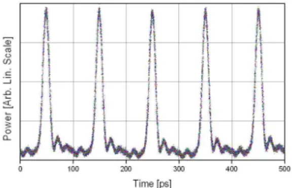
Non averaged sampling scope traces also confirm very stable pulse train generation, as shown in Fig.
7.
Fig. 5. RF spectrum of the optoelectronic converted signal. The super-mode beating noise near 26 MHz is completely suppressed below –125 dBc/Hz (resolution bandwidth = 10 KHz).
Fig. 6. Phase noise over 10 Hz to 1 MHz. The noise indicates ∼92 femtosecond pulse timing jitter.
Fig. 7. Non-averaged sampling scope (bandwidth:
50 GHz) traces of the mode-locked output showing very clear pulses.
IV. Conclusion
We report a wideband flat-topped optical comb source generated from a semiconductor-based mode-locked fiber ring laser with an intra-cavity high finesse Fabry-Perot etalon. By deliberately adjusting the matching condition between the FPE transmission peaks and laser cavity resonance frequencies, we achieve a stable 10 GHz comb with greater than 200 comb lines within a spectral power variation below 1 dB, the largest value obtained from a similar mode-locked laser in our knowledge. Greater than 25 dB of the spectral peak to deep ratio at 0.01 nm resolution, ~ 92 femtosecond timing jitter over 1 kHz to 1 MHz range, and non-averaged pulse time traces also confirm very stable optical frequency comb lines.
References
[1] H. Takara, T. Yamamoto, H. Masuda, T.
Morioka, M. Abe, H. Takahashi,
“Over-1000-channel ultradense WDM transmission with supercontinuum multicarrier source”, J.
Lightwave Technol., vol. 24, no. 6, 24, pp.
2311-2317, Jun.2006.
[2] P. J. Delfyett, S. Gee, M. T. Choi, H.
Izadpanah, W. Lee, S. Ozharar, F. Quinlan, and T.
Yilmaz, “Optical frequency combs from semiconductor lasers and applications in ultrawideband signal processing and communications”, J. Lightwave Technol., vol. 24,
no. 7, pp. 2701-2719, Jul. 2006.
[3] Z. Jiang, D. S. Seo, S.-D. Yang, D. E. Leaird, R. V. Roussev, C. Langrock, M. M. Fejer, and A.
M. Weiner, “Four user, 2.5 Gb/s, spectrally coded O-CDMA system demonstration using low power nonlinear processing”, J. Lightwave Technol., vol.
23, no. 1, pp. 143-158, Jan. 2005.
[4] M. Song, C. M. Long, Rui Wu, D. S. Seo, D.
E. Leaird, and A. M. Weiner, “Reconfigurable and Tunable Flat-top Microwave Photonic Filters Utilizing Optical Frequency Combs”, IEEE Photon.
Technol. Lett, vol. 23, no. 21, pp. 1618-1620, Nov.
2011.
[5] D.S. Seo, and A.M. Weiner, "Ultrashort Optical Pulse Generation at 10 GHz by Pulse Compression of Actively Mode-Locked Fiber Laser Output", J. IKEEE, vol. 9, no. 2, pp. 115-122, Dec. 2005.
[6] T. Kuri, T. Nakasyotani, H. Toda, and K.
Kitayama, “Characterizations of Supercontinuum Light Source for WDM Millimeter-Wave-Band Radio-on-Fiber Systemssuper continuum“, IEEE Photon. technol. Lett., vol. 17, no. 6, pp. 1274-1276, Jan. 2005.
[7] R. Wu, V. R. Supradeepa, C. M. Long, D. E.
Leaird, and A. M. Weiner, “Generation of very flat optical frequency combs from continuous-wave lasers using cascaded intensity and phase modularors driven by tailored radio frequency waveforms”, Opt. Lett., vol. 35, no. 19, pp.
3234-3236, Oct. 2010.
[8] S. Ozharar, F. Quinlan, I. Ozdur, S. Gee, and P.
J. Delfyett, “Ultraflat optical comb generation by phase-only modulation of continuous-wave light”, IEEE Photon. technol. Lett., vol. 20, no. 1, pp.
36-38, Jan. 2008.
[9] F. Quinlan, C. Williams, S. Ozharar, S. Gee, and P. J. Delfyett, “Self-stabilzation of the optical frequencies and the pulse repetition rate in a coupled optoelectronic oscillator”, J. Lightwave Technol., vol. 26, no. 15, pp. 2571-2577, Aug. 2008.
[10] I. Ozdur, M. Akbulut, N. Hoghooghi, D.
Mandridis, S. Ozharar, F. Quinlan, and P. J.
Delfyett, “A semiconductor-based 10 GHz optical comb source with sub 3-fs shot-noise-limited timing jitter and ~500-Hz comb linewidth”, IEEE Photon. Technol. Lett., vol. 22, no. 6, pp. 431-433,
Mar. 2010.
[11] S. Gee, S. Ozharar, F. Quinlan, and P. J.
Delfyett, "High-precision measurement of free spectral range of etalon", Electron. Lett., vol. 42, no. 12, pp. 715-716, Jun. 2006.
[12] D. S. Seo, D. E. Leaird, A. M. Weiner,
“Tuning power spectrum of semicondctor and intra-cavity-etalon based mode-locked laser via detuning”, Electron. Lett., vol. 49, no. 18, pp.
1173-1175, vol. 42, no. 12, Aug. 2006.
BIOGRAPHY
Leaird, Daniel E. (Regular Member)
1980: B.S. degree in Physics, Ball State University, USA
1996: M.S. degree in Electrical Engineering, Purdue University, USA
2000: Ph.D. degree in Electrical Engineering, Purdue University, USA
1994 ~ Present: Senior Research Scientist, School of Electrical and Computer Engineering, Purdue University, USA
<Research interests> Ultrashort pulse shaping, Microwave photonics, All optical switching
Weiner, Andrew M. (Regular Member) 1979: B.S. degree in Applied Physics, MIT, USA 1981: M.S. degree in Applied Physics, MIT, USA 1984: Sc.D. in Electrical Engineering, MIT, USA 1984 ~ 1992: Researcher, Belcore, USA
1992 ~ Present: Professor, School of Electrical and Computer Engineering, Purdue University, USA
<Research interests> Ultrafast optical signal processing, Microwave photonics, Optical communications
Seo, Dongsun (Life Member)
1980: B.S. degree in Electronics, Yonsei University
1985: M.S. degree in Electronics, Yonsei University
1989: Ph.D. degree in Electrical Engineering, Univ. of New Mexico, USA
1990 ~ Present: Professor, Dept. of Electronics, MyongJi University
<Research interests> Optical pulses, Optical CDMA, Microwave photonics, Coherent optical
communications