http://dx.doi.org /10.5228/KSTP.2012.21.2.96
모바일용 도광판의 게이트 자동절삭 및 사출/압축 성형법을 적용한 사이클 타임 저감에 관한 연구
민인기1, 2 · 김종선2 · 윤경환#
Cycle Time Reduction with Automated Gate Cutting Mechanism and Injection/Compression Molding for Producing Mobile LGP
I. K. Min, J. S. Kim, K. H. Yoon
(Received November 24, 2011 / Revised December 23, 2011 / Accepted January 2, 2012)
Abstract
Conventional injection molding system for producing extremely thin-wall parts such as Light Guide Plates(LGP’s) for mobile displays is at the limit of its capability due to its tendency to develop frozen layers and the critical speed of injection. The molten polymer in the cavity freezes quickly as its heat is rapidly transferred to the mold base. Many attempts have been tried in the past to overcome this problem. The present study used the injection/compression molding technology to produce a thin-wall part, with enhanced features such as an automated mechanism for cutting gates. As a result, the total cycle time was reduced by almost 35 seconds, resulting in a productivity increase by 30%.
Key Words : Injection Molding, LGP, Automated Gate Cutting System, Injection/Compression Molding
1. 서 론
모바일 디스플레이 및 TV등의 제품은 대부분 사출 성형에 의한 플라스틱 제품으로 만들어진다 고 해도 과언이 아니며, 또한, 제품의 디스플레이 부분을 담당하는 BLU의 핵심 부품인 도광판 또 한 사출성형 공정으로 만들어진다. 최근 휴대기기 에서부터 TV에 이르기까지 경박단소한 제품이 주 류를 이루고 있는 추세이며, 이를 성형하기 위한 정밀 사출기술에 대한 연구 또한 시급한 상황이다.
제품의 두께가 얇아짐에 따라 기존의 일반사 출 성형방법으로는 제품의 특성을 얻기엔 한계 가 있다. 이에 박육제품이나 TV 하우징 등의 표 면 광택도 향상 및 성형성 향상을 위하여 유도가 열 방식이나 증기를 이용한 금형 급속 가열 등의
RHCM(Rapid Heating and Cooling Mold) 방법을 이 용하여[1~3] 제품 생산에 이용하고 있다. 그 외에 도 사출/압축 성형방법을 이용하여 도광판내의 전 사성의 향상 및 휨 개선, 잔류응력 및 복굴절 저 감에 대한 연구가 이루어지고 있다[4~6]. 또한, 생 산성의 향상을 위하여 냉각효과 향상을 위한 형 상적응형 냉각채널을 이용하거나 통계적 기법을 이용한 최적화 방법 등 다양한 연구들이 이루어 지고 있지만 게이트 절삭 등 성형 후 제품의 후 처리에 대한 문제는 쉽게 접근하지 못하고 있는 실정이다[7~10].
따라서, 본 논문에서는 사출/압축 성형을 이용 하여 박육 제품의 성형성을 향상시키고, 여기에 성형 후, 후 처리 작업 중 하나인 게이트 절삭 공 정을 제거하기 위한 형내 게이트 자동절삭 시스
1. 단국대학교 대학원 기계공학과 2. 한국생산기술연구원
# 교신저자: 단국대학교 대학원 기계공학과 E-mail: [email protected]
Injection/Compression molding Core compression
molding
Total Compression molding
Injection compression mode
Injection press mode
Classification by Mold structure
Classification by Compression method Injection/Compression
molding Core compression
molding
Total Compression molding
Injection compression mode
Injection press mode
Classification by Mold structure
Classification by Compression method
Injection with initially high clamping force and packing
Injection with initially high clamping force and packing Mold close
Mold close EjectionEjection
Mold close with low clamping force
Mold close with
low clamping force InjectionInjection Mold opened(δ) by injection pressure
Mold opened(δ) by injection pressure
Mold close with high clamping force
Mold close with
high clamping force EjectionEjection
Mold opened(δ) Injection with open state
Mold close with
high clamping force Ejection Mold opened(δ) Injection with
open state
Mold close with
high clamping force Ejection (a)
(b)
(c) 템을 도입하여[11] 성형 시간 단축 및 생산성 향
상에 기여하고자 하였다.
2. 사출/압축성형 및 게이트 자동절삭 시스템
2.1 사출/압축 성형
최근에 사출성형공정이 광학부품에 많이 적용 되기 시작하면서, 미세패턴의 충전 및 광 특성의 향상 등을 위해 사출/압축 성형에 대한 관심이 높 아지고 있다. 일반 사출 성형방식이 금형을 닫은 상태에서 용융수지를 고압으로 주입하여 보압 및 냉각과정을 거치는 공정이라면, 이와는 달리, 사 출/압축공정은 충전이 시작되기 전에 금형을 미리 열어두거나, 초기에 낮은 형체력을 설정해두어 충 전 중 금형이 열리게 한 후 높은 형체력으로 형 폐하여 압축을 가하는 방식이다.
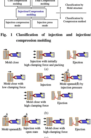
사출/압축은 Fig. 1에서 보이는 바와 같이 금형 구조 및 압축 방법에 따라 분류할 수 있다. 금형 구조에 의한 분류는, 금형을 닫아놓은 상태에서 코어의 작동만으로 압축하는 코어압축(partial or core compression)방식과 이동측 금형 전체를 작동 하여 압축하는 방식(total compression)으로 분류할 수 있으며, 압축 방법에 따른 분류는 사출압축모 드(injection compression mode)와 사출 프레스 모드 (injection press mode)로 구분할 수 있다.
사출/압축 모드는 초기에 매우 작은 형체력으로 금형을 체결하고 있다가 사출과정에서 수지가 캐 비티 내에 유입될 때, 사출압력에 의해 이동측 금 형이 뒤로 밀렸다가(δ) 설정값 이상이 되면 두 번 째 형체력이 작용하여 제품을 압축하는 방식이다.
이와는 달리, 사출 프레스 모드는 사출 전에 금형 을 초기 설정치(δ) 만큼 미리 금형을 열어놓았다 가 충전이 완료되면 금형을 닫음으로써 압축을 하는 방식이다. 사출/압축성형 공정 시 금형의 작 동 순서를 Fig. 2 에 일반 사출성형과 비교하여 정 리하였다.
일반적인 사출성형은 용융 수지를 게이트에서 고압으로 주입한 후, 수축한 양은 보압을 통해서 보충하게 된다. 따라서, 성형품은 게이트 부근에 서 금형 내 수지 압력이 높고 게이트에서 멀어 질수록 압력이 낮아지는 압력 분포를 가지게 되 며, 이로 인한 잔류응력 및 복굴절의 분포가 발생 하게 된다. 반면에, 사출/압축성형은 금형면 전체 에 균일한 압력을 가할 수 있어 제품 내에 유동 에 의한 배향을 완화시키고, 제품 내 전체적으로
Fig. 1 Classification of injection and injection/
compression molding
Fig. 2 Injection molding mechanism; conventional injection molding(a), injection/compression molding with injection compression mode(b) and injection press mode(c), respectively
잔류응력 및 복굴절의 분포를 줄일 수 있다. 또한, 사출압력의 저감, 치수정밀도 향상 및 전사성 향 상이 가능하며, 상대적으로 낮은 온도에서 성형이 가능하기 때문에 사이클 타임을 단축시킬 수도 있다. 하지만, 금형가공에 있어서 정밀도 향상, 압 축 시 역류방지를 위한 게이트 차단(gate sealing) 방법, 성형기의 정밀 제어 등, 성형변수가 늘어나 는 단점이 있다[4~5].
2.2 게이트 자동절삭 시스템
제품이 성형부터 포장까지의 출하되는 과정을 살펴보면, 본 연구의 대상인 BLU-LGP제품의 경우 에 성형(20~25sec), 취출(5sec), 적재(5sec), 게이트 절삭(10sec), 이물질 검사(10sec), BLU 조립(30sec), 제품검사(30sec), 포장(10sec) 등의 단위 공정들로
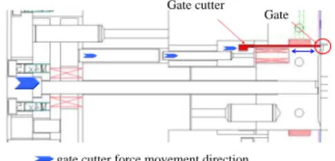
Gate cutter Gate
gate cutter force movement direction
(a) (b) (c)
Fig. 3 A model of 2.5 inch LGP (a) and photographs of installed mold; stationary (b) and movable part (c)
Fig. 4 A structure of automated gate cutting system
(1) Mold closing (2) Initially mold open (3) Injection
(4) Compression (5) Gate cut (6) Cooling
(7) Demolding (8) Ejecting
Mold opened (δ) δ
Cutter
Gate
Fig. 5 An automated gate cutting mechanism during injection/compression molding process
나눌 수 있으며, 생산부터 출하(포장)까지 걸리는 시간은 개당 약 2분 5초 정도가 걸린다. 생산 과 정 중에 게이트 절삭 시 발생하는 미세 먼지나 스크럽 등이 제품의 이물로 작용하여 품질 검사 단계에서 제품 불량으로 판정되는 경우가 많아 생산율이 저하됨을 볼 수 있다. 따라서, 중간에 게이트 절삭과정을 없애면 이물에 의한 불량율을 줄일 수 있을 뿐만 아니라 검사자의 시력손상요 인 저하에도 도움을 줄 수 있다.
본 연구에서 사용한 제품 및 금형은 Fig. 3에 보 이는 바와 같이 대각선 길이가 약 2.5inch, 두께 0.3mm인 2-cavity의 구조로 되어 있다. cavity는 사 출/압축 과정 시, 사출 시작 전 금형이 열린 상태 에서 수지가 새어 나오지 않도록 밀폐되어 있는 구조로 설계하였으며, 게이트 부분에는 사출 후 압축과정이 진행되는 과정에서 형폐동작과 동시 에 게이트를 자동으로 절삭할 수 있는 절삭 날 (gate cutter)이 설치 되어 있다. 본 시스템의 과정 을 보면 먼저 사출 시작 전 초기 설정한 형개거 리만큼 금형이 열린 상태에서(δ) 사출이 시작된다.
이후, 사출이 완료되면 높은 형체력으로 형폐가 이루어지고 압축과정이 진행된다. 이와 동시에 게 이트 절삭기구(gate cutter)가 전진하여 게이트절삭 이 이루어진다. 이후에 냉각과정을 거친 후 제품 을 취출하면 제품과 스프루 부분이 분리된 성형 품을 얻을 수 있다. 본 실험에서 사용한 게이트 자동 절삭구조와 위에서 설명한 과정을 Fig. 4 및 Fig. 5에 개략도로 나타내었다.
3. 실 험
3.1 성형 수지 및 사출성형기
본 실험에서 사용된 수지는 Mitsubshi 社의 Iupilon HL-4000(Polycarbonate)을 사용하였다. 수지의 유리 전이온도는 144℃이고 수축률은 0.4~0.6% 의 투명 수지로서 내후성, 내화학성, 경도, 외관, 높은 광 투과율 등의 우수한 특성을 가져 광학 관련 제품 에 많이 적용되고 있으며 그 물성을 아래의 Table 1 에 나타내었다.
또한, 실험에 사용된 사출 성형기로는 Fig. 6 에 보이는 MEIKI 社의 LGP-40 전동식 사출기를 사용 하였으며 형체력은 40 ton, 최대 사출 속도는 400 mm/s, 그리고 특별 사양으로 사출/압축 성형 기능 이 포함되어 있다. 또한, 분리된 제품의 취출을 위해 취출로봇 및 흡착식 지그를 사용하였다.
Table 1 Material properties of HL-4000(PC)
Properties Units Value
Density g/cm3 1.2
MFR g/10 min 60
Shrinkage % 0.5
Deflection Temp. ℃ 123 Glass trans. Temp. ℃ 144
(a) (b)
Suction jig
Suction jig Suction jig
Suction jig
(a) (b)
Fig. 6 Injection molding machine(LGP40) (a) and ejecting robot (b)
Table 2 Process conditions for injection molding
Factor Condition Unit
Mold temp. 80 ℃
Melt temp. 340 ℃
Injection speed 360 mm/s Cooling time 7 sec Extra mold open dist. 0.02 mm Compression force 220 kN
3.2 성형 실험
성형실험은 일반사출 성형과 사출/압축 공정을 비교하여 진행하였으며, 성형조건으로는 금형온도 80℃, 수지온도 340℃로 설정하였으며, 사출속도 는 사출기 최대 허용 속도의 90%로 설정하여 실 험하였으며 사출/압축 시 초기 형개거리(δ)는 0.02 mm 로 설정하여 실험을 진행하였다. Table 2 에 성 형조건을 정리하였다.
4. 실험결과 및 분석
4.1 성형결과
성형 과정 중의 게이트 자동 절삭 기능을 사용 하지 않고 일반 사출 성형과 사출/압축 성형의 결 과를 Fig. 7 (a), (b)에 보이고 있다. 일반사출 성형 을 이용하여 생산한 제품은 미성형 됨을 볼 수 있는 반면 사출/압축 성형을 적용한 경우에는 미 성형 없이 성형 된 결과를 볼 수 있다. 일반 사출 에서는 금형 온도가 낮은 조건에서 용융된 수지 가 캐비티 내로 유입되기 때문에 급격한 고화로 인하여 미충전이 발생한 것으로 판단된다. 게이트 자동절삭 및 사출/압축을 적용한 경우에는 Fig.
7(c)와 같이 성형 과정에서 게이트와 제품이 분리 된 것을 보여주고 있다.
(a) (a)
(b) (b)
(c) (c)
Fig. 7 Product filling comparisons of conventional injection molding (a), injection/compression molding (b) and gate cut sample after ejection (c)
Molding and ejection (15 sec) Molding and ejection
(15 sec)
Loading (5 sec) Loading (5 sec)
Assembly (30 sec) Assembly
(30 sec)
Appearance Inspection (30 sec) Appearance Inspection
(30 sec)
Packaging (10 sec) Packaging
(10 sec)
Injection/compression molding and ejection (10 sec) Injection/compression molding and ejection
(10 sec)
Loading (5 sec) Loading (5 sec)
Assembly (30 sec) Assembly (30 sec)
Appearance Inspection (30 sec) Appearance Inspection
(30 sec)
Packaging (10 sec) Packaging
(10 sec)
Cycle time = 120 sec Cycle time = 85 sec Conventional injection molding Injection/Compression molding
Dust inspection (0 sec)
Gate cutting &
Dust inspection omitted (0 sec) Gate cutting
(0 sec)
Dust inspection (0 sec)
Gate cutting &
Dust inspection omitted (0 sec) Gate cutting &
Dust inspection omitted (0 sec) Gate cutting
(0 sec) Gate cutting
(grinding, polishing, cleaning) (20 sec)
Dust inspection (10 sec) Gate cutting
(grinding, polishing, cleaning) (20 sec)
Dust inspection (10 sec) Dust inspection
(10 sec)
Fig. 8 The cycle time reduction via automatic gate cutting and injection/compression molding
4.2 생산성 비교
게이트 자동 절삭 기능을 이용하여 제품의 성 형부터 출하 시의 포장과정까지 각각의 할당 시 간을 비교한 결과를 Fig. 8에 나타내었다. 사출/압 축 성형 및 게이트 자동절삭 기능을 이용할 경우,
사출/압축으로 인한 성형 시간 단축과 게이트 절 삭 과정과 절삭 후 이물검사 공정이 제거되기 때 문에 제품 한 단위당 생산시간은 약 2분에서 1분 25초 정도로 약 30% 정도가 절감되는 효과를 볼 수 있다.
5. 결 론
본 연구에서는 박육 제품의 성형 시 사출/압축 기능을 이용하여 낮은 금형온도 조건에서도 용이 하게 제품을 생산할 수 있음을 보였으며 성형과 정 중에 게이트를 자동으로 절삭할 수 있는 기구 를 금형 내에 추가하여 제품의 성형부터 출하까 지 이루어지는 총 생산 시간을 약 30% 정도로 줄 일 수 있음을 보였다. 본 연구를 통하여 현장에서 작업자들의 숙련도에 따라 발생할 수 있는 제품 불량(이물불량 등) 및 작업자의 피로도를 줄이는 데 큰 기여가 될 것이라 판단 되며 제품의 가격 경쟁력을 높이는데 도움이 될 것이라 본다.
후 기
본 연구는 지식경제부 재원과 한국산업기술평 가관리원 지원의 산업원천기술개발사업(과제번호:
10033710, 10033493)의 지원으로 수행되었으며, 이 에 관계자 여러분께 감사를 드립니다.
참 고 문 헌
[1] G. Wang, G. Zhao, H. Li, Y. Guan, 2010, Research of Thermal Response Simulation and Mold Structure Optimization for Rapid Heat Cycle Molding Processes, Respectively, with Steam Heating and Electric Heating, J. Mater. Des, Vol. 31, No. 31, pp.
382~395.
[2] M. C. Song, Z. Liu, M. J. Wang, T. M. Yu, D. Y.
Zhao, 2007, Research on Effects of Injection Process Parameters on the Molding Process for
Ultra-thin Wall Plastic Parts, J. Mater. Process.
Technol., Vol. 187-188, No. 12, pp. 668~671.
[3] S. J. Liu, C. Y. Chang, 2003, The Influence of Processing Parameters on Thin-wall Gas Assisted Injection Molding of Thermoplastic Materials, J.
Reinf. Plast. Compos., Vol. 22, No. 8, pp. 711~731.
[4] I. K. Min, J. S. Kim, Y. B. Ko, H. P. Park, K. H.
Yoon, C. J. Hwang, 2006, An Experimental Study on The Improvement of Pattern Replication and Birefringence in LGP by Adding Compression Effects, Trans. Mater. Process., Vol. 15, No. 1, pp.
27~33.
[5] H. Ito, H. Suzuki, 2009, Micro-features Formation in Injection Compression Molding, J. Solid Mech.
Mater. Eng., Vol. 3, No. 2, pp. 320~327.
[6] J. Y. Ho, J. M. Park, T. G. Kang, S. J. Park, 2011, Three-Dimensional Numerical Analysis of Injection- Compression Molding Process, Polym. Eng. Sci., Vol. 52, No. 4, pp. 1~11.
[7] D. E. Dimla, M. Camilotto, F. Miani, 2005, Design and Optimisation of Conformal Cooling Channels in Injection Moulding Tools, J. Mater. Process.
Technol., Vol. 164-165, pp. 1294~1300.
[8] H. Hassan, N. Regnier, C. Lebot, C. Pujos, G.
Defaye, 2009, Effect of Cooling System on the Polymer Temperature and Solidification during Injection Molding, Appl. Therm. Eng., Vol. 29, No.
8-9, pp. 1786~1791.
[9] Y. Hioe, K. C. Chang, K. Zuyev, N. Bhagavatula, J.
M. Castro, 2008, A Simplified Approach to Predict Part Temperature and Minimum “Safe” Cycle Time, Polym. Eng. Sci., Vol. 48, No. 9, pp. 1737~1746.
[10] W. C. Lo, K. M. Tsai, C. Y. Hsieh, 2009, Six Sigma Approach to Improve Surface Precision of Optical Lenses in the Injection-molding Process, Int. J. Adv.
Manuf. Technol., Vol. 41, No. 9-10, pp. 885~896.
[11] T. Ebina and Aichi-ken, 1999, Method of releasing thin discs in molding, US Patent No. 5,997,788.