NZ-DSF를 갖는 8×40 Gbps WDM 시스템에서 개량된 MSSI 기법을 이용한 왜곡된 RZ 신호의 보상
Compensation for Distorted RZ Signals in 8×40 Gbps WDM System with NZ-DSF using Modified MSSI
이성렬
* Seong-Real Lee *
요 약
본 논문에서는 비 영 분산 천이 광섬유로 구성된 8×40 Gbps WDM 시스템에서 모든 채널을 효과적으로 보 상할 수 있는 광 위상 공액기의 최적 위치와 광섬유의 최적 분산 계수 값을 도출하는 수치적 방법을 제안하였 다. 그리고 이 방법의 유용성을 확인하기 위하여 도출된 두 최적 파라미터를 갖는 시스템에서의 보상 특성을 현재 일반화된 MSSI (Mid-Span Spectral Inversion)에서의 보상 특성과 비교하였다. 유도된 두 최적 파라미터가 WDM 시스템에 적용되면 왜곡된 8-채널 신호들의 보상을 2 dB 이내의 전력 패널티로 크게 개선시킬 수 있는 것을 확인하였다. 그리고 두 최적 파라미터들은 최적 값을 찾는 순서에 크게 관계없지만 두 파라미터가 서로 의존해서 구해져야 한다는 것을 확인할 수 있었다.
Abstract
In this paper, the numerical methods of searching the optimal position of optical phase conjugator (OPC) and the optimal dispersion coefficients of fiber sections are proposed, which are able to effectively compensate overall channels in 8×40 Gbps WDM system with non zero - dispersion shifted fiber (NZ-DSF) as an optical fiber. And the compensation characteristics in the system with two induced optimal parameters are compared with those in the system with the currently used mid-span spectral inversion (MSSI) in order to verify the availability of the proposed methods. It is confirmed that the compensation extents of the distorted 8-channel signals are improved within 2 dB power penalty by applying the induced optimal parameters into WDM system.
It is also confirmed that two optimal parameters less related with the searching procedure of these optimal values, only if these depend on each other.
Key words : MSSI, WDM system, Optical Phase Conjugator, Optimal parameters, RZ format
* 목포해양대학교 해양전자통신공학부 (Div. of Marine Electro. & Comm. Eng., Mokpo National Maritime University)
‧ 제1저자 (First Author) : 이성렬
‧ 접수일자 : 2006년 8월 10일
I. Introduction
Since the 10 Gbps optical transmission systems were realized, dispersion shifted fiber (DSF) instead of conventional single mode fiber (SMF) is widely used in
order to overcome signal distortion due to chromatic
dispersion in optical fiber. But, the crosstalk owing to
Kerr effects, especially four-wave mixing (FWM) is
appeared in multi-channels transmission system with
DSF, consequently serious problem should be generated
in the case of expanding to WDM system[1]. In mostly recent, the fiber overcoming this problem of DSF is developed for realizing multi-channel WDM system.
The zero dispersion wavelength of this new type fiber is appeared beyond transmission bandwidth and chromatic dispersion of this fiber is relatively large, because FWM effect is more decreased as chromatic dispersion is larger. This fiber is called to non zero - DSF (NZ-DSF) [2].
But, even if NZ-DSF is used to suppress FWM effect, the bit-rate distance product in long-haul WDM system with erbium doped fiber amplifier (EDFA) is limited by self phase modulation (SPM) effect and cross phase modulation (XPM) effect, which are generated owing to high power of optical signal in EDFA[3]. One of the techniques to overcome this limitation is mid-span spectral inversion (MSSI).
Theoretically, this technique overcomes both SPM effect and dispersive effects by using optical phase conjugator (OPC) in mid-way of total transmission length[4].
The serious problems have to be solved in order to apply MSSI technique into the multi-channel transmission system. The first is that a perfectly symmetrical distribution of power and local dispersion with respect to OPC position is formed for nonlinearity cancellation in real transmission links[5]. The second is that the OPC must exhibit the similar conversion efficiency over large bandwidth for increasing number of WDM channels. Fortunately, the second problem is solved by using highly-nonlinear dispersion shifted fiber (HNL-DSF) as a nonlinear medium of OPC because the effective bandwidth of HNL-DSF is wide and flattened [6]. But, the first problem still remains in the perfectly compensating the distorted overall WDM channels.
Furthermore, it is very difficult to obtain the solution simultaneously applying the total transmitting channels, because the WDM channels copropagating in an optical fiber have different wavelengths, even if this problem was solved for a special wavelength. Thus it is require to research the new method, which is able to alternate
with method for solving the mentioned first problem, for implementing OPC in the real WDM systems.
This research focus on the numerical methods of searching the optimal OPC position and the optimal dispersion coefficients of fibers in order to alternate with the method of making the symmetrical distribution of power and local dispersion in real optical link. That is, the optimal position of OPC and the optimal dispersion coefficient of fiber sections are numerically induced and applied into WDM system. The effective- ness of these optimal parameters are numerically verified on the comparison of the compensation charac- teristics in WDM system with the induced optimal parameters and in WDM system with conventional MSSI technique.
The considered WDM system has 8 channels of 40 Gbps. The intensity modulation format is assumed to be RZ. The split-step Fourier method is used for numer- ical simulation, which is the basic numerical method for analyzing the phenomenon of optical signal propa- gation in dispersive and nonlinear optical fiber[7]. The evaluation parameters of compen sation extents are eye-opening penalty (EOP). The XPM effectis neglected in order to simplify the analysis.
Ⅱ. Modeling of WDM system
Consider 8 optical waves with the same polarization copropagating in an optical fiber. Let
Aj
(z,t)be the slowly varying complex field envelope of each wave normalized to make equal to the instantaneous optical power. satisfies the following equation[7].
∂ A j
∂ z = - α 2 A j - i
2 β 2j ∂ 2 A j
∂ T 2 + 16 β 3j
∂ 3 A j
∂ T 3 + i γ j | A j | 2 A j + 2 i γ j | A k | 2 A j
(1)
where j, k = 1,2,…,8 (j≠k),
αis the attenuation
coefficient of the fiber,
λj is the j-th channel signal
wavelength,
β2j is the fiber chromatic dispersion
parameter,
β3j is the third-order chromatic dispersion
M U X M U X
M U X D E M U X OPC
EDFA EDFA EDFA EDFA
PS(L1) PS(0)
Fiber segment
l
1EDFA
PC(L2) PC(0)
lN
EDFA
l
2Latter half section length L2 Former half section length L1
Transmitter Transmitter Transmitter l
s2Transmitter l
s4Transmitter l
s5Transmitter l
s6Transmitter l
s7Transmitter l
s8l
s3Receiver
Receiver Receiver
Receiver Receiver Receiver Receiver Receiver
l
c1l
c2l
c4l
c5l
c6l
c7l
c8l
c3l
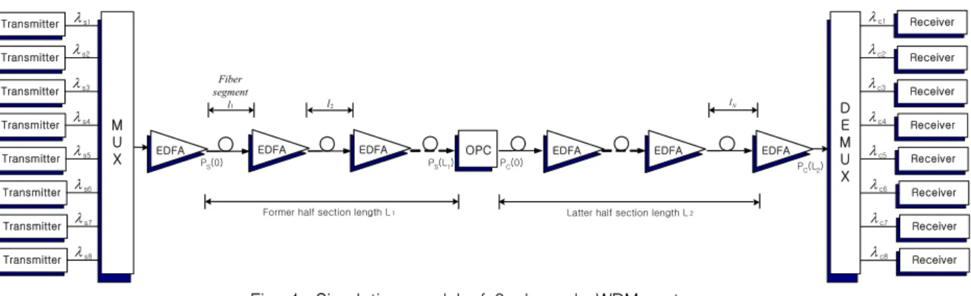
s1Fig. 1. Simulation model of 8-channels WDM system.
parameter, γ j is the nonlinear coefficient and T=t-z/v g , respectively. The last two terms in equation (1) induce SPM and XPM, respectively. The last term, i.e., XPM term is neglected in order to simplify numerical analysis in this paper.
Parameter Symbol & Value
Type NZ-DSF
Chromatic dispersion
D 1x
= 6 ps/nm/km Nonlinear refractive indexn 2
= 2.5×10⁻²⁰
m2
/W Attenuation α = 0.2 dB/km Effective core areaA eff
= 72 μm2
Table. 1. Fiber parameter assumptions.Fig. 1 shows a configuration of intensity modulation/
direct detection (IM/DD) WDM system with OPC placed at mid-way of total transmission length. In Fig.
1, total transmission length (L) is divided two sections of respective length L 1 (=L/2) and L 2 , and each fiber section consist of 10 amplifier spans of length l=50 km.
Fiber parameters assumed for numerical simulations throughout this paper are summarized in Table 1 [8].
Watanabe and Shirasaki generalized the MSSI by considering that above fiber parameters can be func- tions of distance z[4]. The general condition for perfect distortion compensation is shown to be
β 2j (- z 1 ' ) P j (- z 1 ' )γ j (- z 1 ' ) =
β 2j ( z 2 ' )
P j ( z 2 ' )γ j ( z 2 ' ) (2)
where
β3j is neglected.
This relation means that perfect distortion compen- sation can be obtained by providing the equal ratio of the dispersion and nonlinearity at the corresponding
positions -z 1 ' and z 2 '. That is, the OPC need not be placed at the mid-way of total transmission length and dispersion coefficient of latter half section need not equal with that of former half section, which are dependent of the signal wavelength. However, the equation (2) also means that it is not easy to find out the common OPC position and dispersion coefficient of each fiber sections available for total allocated WDM wavelengths in real transmission link, because equation (2) is dependent on the wavelength. Thus, this research is devoted to find out the optimal OPC position and dispersion coefficient of each fiber sections, which are available for 8 WDM channels. The optimal OPC posi- tion is found out by evaluating the compensation cha- racteristics as a function of the OPC position (z OPC ) varied within one span length (±25 km) from the mid-way. The difference between z OPC and z mid , i.e., z OPC- z mid is called to the OPC position offset,
Δz. And the optimal dispersion coefficient of each section is also found out by evaluating the compensation cha- racteristics as a function of dispersion offset,
ΔD 1x ( x=1,2). The dispersion offset is defined to difference of dispersion coefficient between two fiber sections, i.e.,
ΔD 11 =D 11 -D 12 and
ΔD 12 =D 12 -D 11 .
Each laser diode in transmitter of Fig. 1 is externally
modulated by an independent 40 Gbps 128(=2 7 ) pseudo
random bit sequence (PRBS). And output electric field
of RZ format signal from external optical modulator is
assumed to be second-order super-Gaussian pulse. The
direct detection receiver of Fig. 1 consist of the pre-
P
S(L
1)
Pump LD
P
C(0) HNL-DSF (Z
0)
P
PEDFA
EDFAOBPF OBPF
A
C(0) A
S(L
1)
HNL-DSF loss : a
0= 0 . 61 dB / km
HNL-DSF nonlinear coefficient : g
0= 20 . 4 W
-1km
-1HNL-DSF zero dispersion wavelength :
HNL-DSF length :
HNL-DSF dispersion slope : Pump light power : Pump light wavelength :
nm 0 .
0
= 1550 l km z
0= 0 . 75
km nm ps d
dD
0/ l = 0 . 032 /
2/ dBm
P
p= 18 . 5
p
= 1549 . 75 nm l
Fig. 2. OPC using HNL-DSF.
amplifier of EDFA with 5 dB noise figure, the optical filter of 1 nm bandwidth, PIN diode, pulse shaping filter and the decision circuit[9]. The receiver bandwidth is assumed to be 0.65×bit-rate.
Fig. 2 shows the configuration of the OPC using HNL-DSF, and its parameters. The conversion effi- ciency η is defined as a ratio of the FWM product power to the input probe (signal) power[10]. The 3-dB bandwidth of η for the OPC in Fig. 2 is obtained to 48 nm (1526~1574 nm).
The unequal channel spacing proposed by F. Forghieri et al. is used to completely suppress the crosstalk due to FWM effects [11]. The allocated wavelengths of each channel used in this research are 1550.0, 1550.7, 1551.7, 1552.5, 1553.4, 1553.9, 1555.0 and 1555.6 nm, thus the signal wavelengths and the conjugated wavelengths are within 3-dB bandwidth of η.
Ⅲ. Simulation results and discussion
Fig. 3. EOP as a function of pump light power.
Fig. 3 shows eye opening penalty (EOP) of channel 1 and 8, the wavelength difference of these channels is most, as a function of pump light power of OPC when the input (launching) powers of each channel are fixed
to 0 dBm. The optimal pump light power for RZ trans- mission is obtained to be 15.3 dBm.
Fig. 4 shows EOP of overall channels as a function of the launching power in WDM system with conven- tional MSSI technique. It is shown that EOPs are more
Fig. 4. EOP as a function of the launching power in WDM system with MSSI.
degraded as the signal wavelengths are more deviated from the zero dispersion wavelength of HNL- DSF OPC. The difference of compensation extents between the channels is resulted from the asymmetrical distri- bution of power and local dispersion. Thus, it is restrict to expand channel numbers in directly applying MSSI using HNL-DSF OPC to WDM systems.
Fig. 5. EOP differences as a function of Δz for ΔD
1x
= 0 ps/nm/km.Fig. 5 shows EOP difference between channel 1 and
8 depending on the OPC position offset,
Δz in order to find out the best OPC position. If WDM channels had the relatively high launching power, the difference of EOP between channel 1 and 8 is so very large that is impossible to find out optimal parameter values, this feature is quite unlike Fig. 5. For this reason, the launching powers are assumed to be 0 dBm in the case of searching optimal parameter values. It is shown from Fig. 5 that the optimal OPC position, which result in the smallest EOP difference between channel 1 and 8, is 499 km(
Δz=-1 km).
Fig. 6. EOP differences as a function of ΔD
1x
when the OPC placed at Δz=-1 km.Fig. 6 shows EOP difference between channel 1 and 8 depending on the dispersion offset,
ΔD 1x when the OPC placed at the position obtained from results of Fig. 5. It is shown from Fig. 6 that EOP differences depending on
ΔD 11 under the condition of
ΔD 12 =0 ps/nm/km is reverse of EOP differences depending on
ΔD 12 at
ΔD 11 =0 ps/nm/km. The best
ΔD 11 that result in the smallest EOP difference is obtained to -0.015 ps/nm/km in the case of
ΔD 12 =0 ps/nm/km, while the best
ΔD 12 is obtained to +0.015 ps/nm/km in the case of
ΔD 11 =0 ps/nm/km.
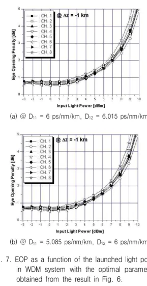
Fig. 7 shows EOP of overall channels as a function of the launching light power in WDM system with the optimal OPC position and the optimal dispersion coe- fficients of fibers determined as the results of Fig. 6.
The compensation extents of WDM system with the obtained optimal parameters are largely improved than the results of Fig. 4. That is, if 1 dB EOP is allowed
for performance criterion, it is confirmed that power penalties are within 1 dB in the all case. This fact means that overall channels are compensated to the similar extents, when the optimal parameters were applied to conventional WDM system when the condi- tion of the symmetrical distribution of optical power
(a) @ D
11
= 6 ps/nm/km, D12
= 6.015 ps/nm/km(b) @ D
11
= 5.085 ps/nm/km, D12
= 6 ps/nm/kmFig. 7. EOP as a function of the launched light power in WDM system with the optimal parameters obtained from the result in Fig. 6.
and local dispersion was not made.
From above results, it is confirmed that the optimal dispersion coefficient of the second fiber section for efficiently compensating overall channels must be larger by 0.015 ps/nm/km than that of the first fiber section, when OPC placed at optimal position of 499 km.
Up to now, the optimal OPC position is previously
induced, and then the optimal dispersion coefficients
depending on this optimal OPC position is consequently
induced. It is required to exchange the procedure of
finding out the optimal parameters for investigating the
correlation of two optimal parameter.
Fig. 8 and 9 show the results obtained through the same numerical methods with the previous, but the reverse procedure of searching the best parameter. In Fig. 8, the best
ΔD 11 that result in the smallest EOP difference between channel 1 and 8 is obtained to -0.04 ps/nm/km in the case of assuming
ΔD 12 =0 ps/nm/km, while the best
ΔD 12 is +0.04 ps/nm/km in the case of assuming
ΔD 11 =0 ps/nm/km. That is, the difference of optimal dispersion coefficient between two fiber sec- tions is determined to 0.04 ps/nm/km.
Fig. 8. EOP differences as a function of ΔD
1x
in the case of assuming Δz=0 km.
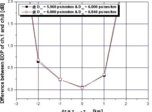
Fig. 9. EOP differences as a function of Δz for ΔD
1x
.It is shown from Fig. 9 that EOP differences between channel 1 and 8 in all cases of D 11 =D 1x +
ΔD 11
and D 12 =D 1x are coincide with those in all cases of D 12 =D 1x +
ΔD 12 and D 11 =D 1x . Here,
ΔD 11 and
ΔD 12 are the optimal value obtained from Fig. 8. In Fig. 9, the best
Δz are obtained to be 0 km in both cases of D 11 =D 1x +
ΔD 11 under the condition of D 12 =D 1x and D 12 = D 1x +
ΔD 12 under the condition of D 11 =D 1x .
Fig. 10 shows EOP of overall channels as a function
of the launching light power in WDM system with the optimal OPC position and the optimal dispersion coeff- icients of fibers determined as the results of Fig. 9. Fig.
10 compare EOP characteristics obtained in the case of optimizing dispersion coefficient of only the second fiber section to D 12 +
ΔD 12 (Fig. 10(a)) with EOP charac- teristics obtained in the case of optimizing dispersion
(a) @ D
11
= 6 ps/nm/km, D12
= 6.040 ps/nm/km(b) @ D
11
= 5.960 ps/nm/km, D12
= 6 ps/nm/kmFig. 10. EOP as a function of the launched light power in WDM system with the optimal parameters obtained from the result in Fig. 9.
coefficient of only the first fiber section to D 11 +
ΔD 11 (Fig. 10(b)). It is shown that EOP charac- teristics of Fig. 10(a) are similar with Fig. 10(b).
By comparing Fig. 7 and 10, it is confirmed that the
optimal parameters values are varied with the procedure
of searching the optimal parameters, but the comp-
ensation extents in Fig. 10 are almost coincide with
those in Fig. 7. That is, the optimal parameters values
related with the finding procedure are not important,
only if two optimal parameters depend on each other.
But, in the case of deciding the optimal dispersion coefficients after deciding the optimal OPC position, OPC position and dispersion coefficients of fiber sec- tion are altered for compensating overall channels to the similar extents. But, in the case of deciding the optimal OPC position after deciding the optimal disper- sion coefficients, only the dispersion coefficient of one fiber section is altered. Thus, the procedure that previously deciding the optimal dispersion coefficients and then deciding the optimal OPC position is more efficient to apply the optimal parameters into WDM system.
Ⅳ. Conclusion
The numerical method of finding out the optimal position of OPC and the optimal dispersion coefficient of fiber sections was proposed, which is expected to replace the method for making the symmetrical distribution of power and local dispersion in MSSI technique.
It was confirmed that the numerical method consi- dered in this research will be available to multi- channel WDM system irrelevant with the finding out procedure of these two optimal parameters only if two optimal parameters depend on each other. The results induced in this research will provide the improvement of the received signal. That is, the compensation extents of the distorted 8-channel signals are improved within 2 dB power penalty by applying the induced optimal parameters into WDM system. Thus, the proposed method will contribute to the widely use of OPC in the compensation of distorted WDM channels due to dispersion and nonlinear effects.
References