인산 도핑 PBI계 막전극접합체를 적용한 고온형 수소연료전지의 전기화학적 내구성 연구
이준기1⋅이찬민1⋅전유권1⋅이홍연1⋅박상선1⋅김태영2⋅김희선3⋅송순호3⋅박정옥2⋅설용건1,†
1연세대학교 화공생명공학과, 2삼성종합기술원, 3연세대학교 기계공학과
The Electrochemical Performance Evaluation of PBI-based MEA with Phosphoric Acid Doped Cathode for High Temperature Fuel Cell
JUNKI RHEE
1, CHANMIN LEE
1, YUKWON JEON
1, HONG YEON LEE
1, SANG SUN PARK
1, TAE YOUNG KIM
2, HEESEON KIM
3, SOONHO SONG
3, JUNG OCK PARK
2, YONG-GUN SHUL
1,†1Department of Chemical and Biomolecular Engineering, Yonsei University, 50 Yonsei-ro, Seodaemun-gu, Seoul 03722, Korea
2Energy & Environment Lab., Samsung Advanced Institute of Technology, 97 Samsung 2-ro, Giheung-gu, Yongin 17113, Korea
3Department of Mechanical Engineering, Yonsei University, 50 Yonsei-ro, Seodaemun-gu, Seoul 03722, Korea
†
Corresponding author :
[email protected]Received
25 July, 2017Revised
25 August, 2017Accepted
30 October, 2017Abstract >> A proton exchange membrane fuel cell (PEMFC) operated at 150℃
was evaluated by a controlling different amount of phosphoric acid (PA) to a membrane-electrode assembly (MEA) without humidification of the cells. The ef- fects on MEA performance of the amount of PA in the cathode are investigated.
The PA content in the cathodes was optimized for higher catalyst utilization. The highest value of the active electrochemical area is achieved with the optimum amount of PA in the cathode confirmed by in-situ cyclic voltammetry. The current density-voltage experiments (I-V curve) also shows a transient response of cell voltage affected by the amount of PA in the electrodes. Furthermore, this in- formation was compared with the production variables such as hot pressing and vacuum drying to investigate those effect to the electrochemical performances.
Key words : High temperature polymer electrolyte membrane fuel cell(고온형 연료 전지), Membrane Electrode Assembly (MEA 막전극전합체), Polybenzi- midazole (PBI), Phosphoric acid(인산)
471
1. Introduction
Polymer electrolyte membrane fuel cells (PEMFCs) at normal operating temperatures lower than 100℃
and in humidified environments have some practical
problems such as CO poisoning of the Pt catalyst,
complexity of the water and heat management sys-
tems, and lower efficiency in redox reactions
1-3).
Many research efforts have been focused over sev-
eral decades on the development of high temperature
proton exchange membrane fuel cells (HT-PEMFCs) operating at high temperatures of 100 to 180℃ un- der anhydrous conditions to solve the afore- mentioned problems. However, existing membranes, such as Nafion membranes, show decrease in the conductivity and plasticity in the cases of de-humid- ification at high temperature due to the evaporation of water and desulfonation over 130℃, which leads to thermal degradation and poor performance.
Therefore, many reports found a way to overcome these shortcomings other types of membranes such as using aromatic polymer and PBI polymer that en- able the operation of PEMFCs at temperatures above 100℃.
During the past few decades, polybenzimidazole (PBI) polymer has been one of the most promising candidates to use for polymer electrolyte fuel cells operation at anhydrous and high temperature con- ditions
4-8). As a fully aromatic heterocyclic polymer, PBI is a basic polymer with excellent thermal and chemical at elevated temperatures (120-200℃) due to its high glass transition temperature (Tg) of 425-436℃ and mechanical toughness by the engineer- ing plasticity with a high compression strength
9,10). Recently, the cell performance of PBI-based MEA for high temperature fuel cells was researched. V.
Kurdakova et al.
11)reported that the addition of the fillers increases the plateau of thermal stability of the PBI-5N membrane and allows 20% higher max- imum power densities compared to the pure PBI-5N MEAs. The SiO
2-Im filler is more effective than MCM-41 at temperatures above 120℃
11).
In recent years, there have been some reports on MEA consisting of PBI polymer membranes or com- posite membranes impregnated with phosphoric acid (PA) at higher temperatures under anhydrous condi- tions. H
3PO
4is a weak acid that supports con- ductivity in anhydrous conditions by forming a hy-
drogen-bonded network
12). There have also been
some approaches in which PA is utilized for elec-
trode applications as well as for membranes for the
purpose of doping the PBI as an ionomer inside the
catalyst layers. Cell performance in the Oono et al.
13)report was improved by both optimizing the amounts
of phosphoric acid doped into the membrane and
diffusing phosphoric acid into the catalyst layer at
the initial stage of cell operation. It was concluded
that approximately 10 mg/cm
2is the optimum
amount of phosphoric acid for a catalyst layer with
a thickness of approximately 20 µm
13). However, the
lifetime or durability of PBI based polymer electro-
lyte membranes is one of the most critical factors for
high temperature fuel cells because there have been
occurrences of PA loss from the membrane, faster
catalyst dissolution in hot acidic medium, sintering
of Pt catalyst, thermal stress on fuel cell parts, ther-
mal degradation of the carbon support and carbon
support corrosion
10-16). Zhai et al.
17)group reported
that the catalyst agglomeration and H
3PO
4leaching
from catalyst layers contributed to the performance
degradation of the MEA during the life test, and that
the degradation of the mechanical properties of
H
3PO
4/PBI membrane negatively impacted the life-
time of the single cell
17). Another group reported that
the enhanced durability of the membrane is attrib-
uted to the improved mechanical strength, which re-
sulted from the presence of Nafion in the Nafion and
PBI matrix. The preliminary results suggested that
the novel H
3PO
4/Nafion-PBI composite membrane is
a good candidate for high temperature PEMFCs for
achieving longer cell lifetimes. Not only PA doped
PBI material itself for the fuel cell operation at high
temperature is important but also a number of MEA
preparation variables affect the performance of PBI
fuel cells. For this reason, the purpose of this study
is the investigation of the variables of PBI full cells
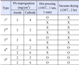
Table 1. Variables for each experiments
TypePA impregnation (mg/cm2)
Hot pressing (150℃, 1 ton,
1 min)
Vacuum drying (120℃, 2 hr) Anode Cathode
1st 2 4 O X
X X
2nd 2 2 X X
X X
3rd 2 6 O X
X X
4th 2 2 X O
2 6 X O
5th 2 2 O O
2 6 O O
in order to obtain the best condition by the proper electrochemical measurements.
In this study, the intermittent performance tests were conducted with varied manufacturing method of PBI-MEA high temperature PEMFC single cells to determine which method resulted in the best per- formance of PBI fuel cell. The production variables were studied using the amount of PA in the electro- des, whether hot pressing was used, and whether vacuum drying was used. The MEA performances were recorded by current-voltage (I-V) curve and electrochemical analysis (cyclic voltammetry, CV) was applied to observe the change of the electro- chemical properties.
2. Experimental
2.1 Preparation of PBI-MEA
In preparation of the polymer electrolyte mem- brane, 160 mol% of PA was doped into poly (2,5-benzimidazole) (ABPBI), in which the weight of 1 mol of the repeating unit was 116 g/mol.
ABPBI was produced by condensing 3,4-diamino- benzoic acid (DABA), which is a monomer, in a sol- ution of polyphosphoric acid. DABA was dissolved in polyphosphoric acid at 150℃ in a nitrogen atmos- phere; the resulting solution was heated to 200℃, and then rapidly condensed into water at room temperature. A solution of the ABPBI using meth- anesulfonic acid as a solvent was cast as a mem- brane by means of the doctor blade method. The methanesulfonic acid (Aldrich) in the membrane was evaporated at 200℃, and the membrane was then immersed in distilled water to separate it from its support. The PA content in the membrane was con- trolled by immersing a dry membrane in PA (60 wt.%) at a temperature of 60℃ for 40 minutes. The
level or amount of acid doped into the polymer elec- trolyte membrane was the initial amount of acid con- tained in the polymer electrolyte membrane before commencing operation of the manufactured fuel cell
18).
The cathode catalyst layer was composed of a Pt-Co alloy supported on carbon (Tanaka Kikinzoku Kogyo, TEC36E52) and polyvinylidene fluoride (PVDF, Aldrich). On the other hand, the anode cata- lyst layer was composed of a Pt-Ru alloy supported on carbon (Tanaka Kikinzoku Kogyo, TEC61E54) and PVDF. The slurry for forming the catalyst layer was prepared by mixing the PVDF solution in n-methyl-2-pyrrolidone (NMP) and a solvent of NMP in an appropriate amount of carbon-supported catalyst. To obtain an un-doped electrode, a home- made bar coater was used to apply the slurry to the carbon paper that had been previously covered with a microporous carbon layer (SGL, 35BC). The Pt loading of the electrode was controlled by adjusting the solvent composition and the coating conditions.
A spray gun was used to prepare an electrode with
the desired level of PA impregnation. A solution of
85 wt.% PA was sprayed on to the surface of the cata-
lyst layer of the un-doped electrode. The doped elec-
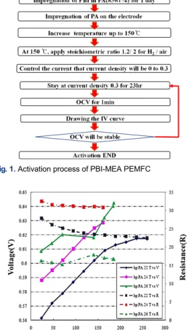
Fig. 1. Activation process of PBI-MEA PEMFC
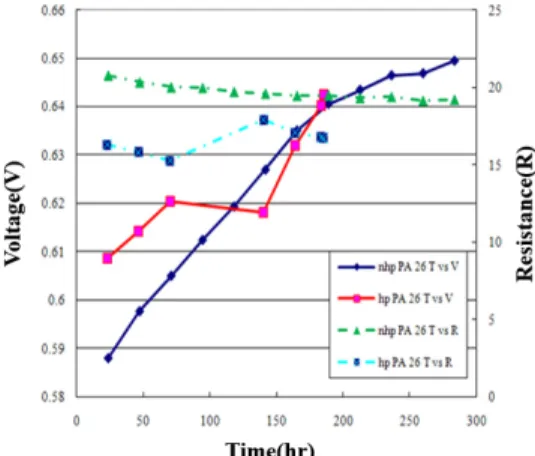
Fig. 2. Variation of OCV and resistance of PBI-MEA PEMFC,
according to amount of Phosphoric acid in electrode of MEAtrode was subsequently dried at a temperature of 120℃
for 2 hours.
Variables for each experiment are shown in Table 1. The variable parameters were the amount of PA impregnated in the cathode (2, 4, and 6 mg/cm
2PA).
One other variable is whether or not to use hot pressing with the conditions of 150℃, 1 ton for 1 minutes in the MEA manufacturing process. Finally, the last variable is whether or not to use a vacuum oven with the conditions of 120℃ for 2 hours, when drying the electrode for impregnation of PA on the catalyst layer.
2.2 Operation process
Dry hydrogen (flow rate: 100 mL/min) for the anode and dry air (flow rate: 250 mL/min) for the cathode were used for the operation of the cell at 150℃. The effective dimensions of the electrode in the MEA were 2.8×2.8 cm
2.
When the temperature of the single cell reaches 150℃, the activation process will be started. For the activation of single cells, the activation process was as follows: first, the current was controlled to change the current density of cell from 0 to 0.3 A/cm
2using several steps, with each step taking 2 minutes. The cells then stayed at a current density of 0.3 A/cm
2for 23 hours. After that, the current was set to OCV, where it remained for 1 minute. The current was then adjusted so that the voltage sweeps from OCV to 0 V, so the I-V curve of the cell can be obtained. This activation process was repeated over and over until the OCV of the cell was stable.
The OCV increased after the start of the activation process and then increased slowly. This process usu- ally takes about a week. The schematic diagram is shown in Fig. 1. At the end of the cell operation, cy- clic voltammetry (CV) was carried out by passing
nitrogen on the cathode side at a temperature of 150℃
to assess the active electrochemical area of electro- des in-situ.
3. Results and discussion
3.1 The amount of impregnated phosphoric acid in the cathode electrode
The impregnated PA in the electrode allows pro-
ton transfer from membrane to catalyst layer. The
amount of PA in catalyst layer was controlled from
2, 4, and 6 mg/cm
2. In the anode electrode, amount
of PA is fixed to 2 mg/cm
2.
Before the operation of the high temperature fuel cell, an activation process for the MEAs composed of PA-doped membrane and PA-impregnated elec- trodes is required to produce the highest perform- ance
19,20). The activation process for the PBI-based PEMFCs is generally much longer than the Nafion-based PEMFCs due to the slow PA absorp- tion rate of PBI inside the catalyst layers which could take around a couple of days
18). Fig. 2 shows the aspect of change in OCV and resistance varies by amount of PA in cathode electrode during the activation process.
The voltage of cell (line) increases during the ac- tivation procedure. The voltage rapidly increases ap- proximately 160 hours (one week) after starting activation. After that point, the rate of increase in voltage decreases. We called that the stable period of the activation procedure. In the stable period, voltage increases slightly during the first 160 hours (a week). The increase in voltage is almost stable 160 hours after the start of activation, and our acti- vation process of the cell ended at the entrance of stable period. The impedance measurements at 1 kHz reflects the ohmic overpotential of the MEAs, which consists of membrane resistance and contact resistance
21). The resistance of the cell (dot line) de- creases as the activation goes on. The decrease of resistance shows nearly the same change as the in- crease of voltage during activation. In the stable pe- riod, the change of resistance also slows. During the activation procedure, which took about a week in this study, the PA in the electrodes and membrane is seen to be redistributed in the MEA before the cell reaches a stable state of constant voltage.
Because the electrodes are not composed with pro- ton-conducting polymers, which can immobilize PA, it is thought that a portion of PA inside the electro- des starts to block the pores of the catalyst layer
during the activation process. For this electrode without using a proton-conducting polymer, the cell performance at high current densities is sacrificed but one of the highest levels was reached at low cur- rent densities compare to the reported PBI-based PEMFCs
4-8). As a higher PA is impregnated in the electrodes, a higher OCV and a lower resistance is obtained. It is possible to achieve a better perform- ance during a 200 hour operation. Shortly after 200 hours, activation polarization, ohmic losses, and con- centration polarization in all areas of the volt- age-current performance curve have confirmed better performances. The shorter time is taken to attain steady-state value for the MEAs with higher amount of PA in the cathode. However, the voltage of cells that contained insufficient amounts of PA in the cathodes respond more slowly to the current applica- tion because the reactions in the electrodes have to overcome a higher barrier created by the low proton accessibility to the catalyst and the limited area available for reaction in the electrodes. From the re- sult in Fig. 2, the contact area between catalyst and ionomer increases with higher content of PA to the cathodes, and the proton conductivity of the mem- brane possibly improves as well by absorbing PA from the electrode which correlated with the higher MEA performance.
As mentioned before, a certain degree of the PA
content in the cathode can enhance the performance
of the PBI-based MEA. When the PA content in the
cathodes is too low, it shows low conductivity due
to insufficient ionomer to effect proton transfer from
membrane to the catalyst. On the other hand, excess
PA content in the cathodes causes the gas network
inside the cathodes to flood
11). Meanwhile, the de-
pendence of cell performance on PA content for the
anode is not marked in this study, but the general
trend that excess- or insufficient PA content in the
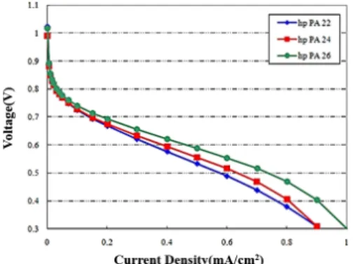
Fig. 3. Variation of I-V curve of PBI-MEA PEMFC, according
to amount of Phosphoric acid in electrode of MEA(a) (b)
Fig. 4. Variation of active surface area (a) and current density
(b) for the PBI-MEA PEMFC, according to amount of Phosphoric acid in electrode of MEAelectrodes causes cell performance to decline does apply to the anode. In Fig. 3, this tendency was also seen that the higher PA content in the cathode shows good performance in the MEA performance. With a high PA impregnation, a good mass transfer activity can be achieved. Moreover, there is generally a rela- tion between the MEA performance and the total available PA content in the electrodes as well as the pattern of dispersal of PA inside the MEA.
It is not clear whether such dispersal remains un- changed during operation of the cells, even though the control over the dispersal of PA in each compo- nent of the MEA is exercised by the initial content of PA. Therefore, the electro- chemical active area of electrodes was evaluated by in-situ CV to inves- tigate an insight into the final PA content in the electrodes. As seen in Fig. 4(a), the active surface area of cell increases with a higher PA impregnated
in electrode. The availability of the active electro- chemical area is directly related to the performance of the MEA, and any increase in active electro- chemical area can be attributed to an increase in the area of contact between the catalyst and the ion- omer
21). It is likely that the higher PA content in the electrodes increases the active electrochemical area which can be closely correlated with the MEA performance. Therefore, we can concluded that the current density of cell increases as the PA amount increases like as the final result in Fig. 4(b). The re- sults show that PA in the electrode acts as an ion transfer path, which invigorates catalyst activity and increases the cell performance.
3.2 Using hot pressing in manufacturing of MEA
Hot pressing is a simple method to assemble the anode, cathode and membrane as a MEA to enhance the interfacial contact between the electrodes and membrane. The inner pore structure during hot pressing process and can be changed to the better performance of the MEA
22,23). Hot pressing has been a very necessary and important process for the prep- aration of MEA for direct methanol fuel cell (DMFC) using GDL-based method, but catalyst coat- ed carbon electrode do not need to be hot pressed onto Nafion membranes to achieve optimum per- formance in a DMFC
24). It can cause the dehydration of Nafion membrane, which may lead to an irrever- sible performance loss of the MEA.
By contrast, for the PA impregnated PBI-MEA,
the PA must be homogeneously distributed since it
acts as an ion path. It is possible to obtain homoge-
neous distribution of PA in MEA by using a hot
pressing process when manufacturing MEA. As not-
ed before, higher PA impregnation results in higher
performance of cells because of PA’s role as an
Fig. 5. Variation of OCV and resistance for the PBI-MEA
PEMFC, according to whether or not it was hot pressed when making MEAFig. 6. Variation of I-V curve for the PBI-MEA PEMFC, ac-
cording to whether or not it was hot pressed or when making MEA(a) (b)
Fig. 7. Variation of active surface area (a) and current density
(b) for the PBI-MEA PEMFC, according to whether or not it was hot pressed when making MEAFig. 8. Variation of OCV and resistance for the PBI-MEA
PEMFC, according to whether or not it went through vacuum drying when making MEAionomer. We expect higher ionomer performance with homogeneous distribution of PA in electrode, catalyst layer and membrane. The hot pressing con- dition of this study is 1 ton, 150℃ and 1 minute.
In Fig. 5, hot pressing results in a positive effect of increasing OCV and lowering resistance in PEMFCs. In the voltage-current performance curve, the effect of hot pressing is confirmed at the region of ohmic loss and concentration polarization as shown in Fig. 6. In hot pressed MEA, PA is maybe more homogeneously distributed and brought a bet-
ter mass transfer activity, indicating an enhancement of the interfacial contact between the electrodes and membrane. Additionally, homogeneous PA dis- tribution brings about large active surface area of the catalyst (Fig. 7(a)), in which a homogeneous PA distribution stimulates catalyst activity. As a result in Fig. 7(b), a higher current density was obtained especially at the limiting current density region when using hot pressing for the enhanced properties in the MEA.
3.3 Using vacuum drying when impregnating PA on electrode
Vacuum-assisted drying processes have an advan-
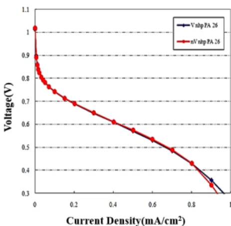
Fig. 9. Variation of I-V curve for the PBI-MEA PEMFC, ac-
cording to whether or not it went through vacuum drying when making MEA(a) (b)
Fig. 10. Variation of active surface area (a) and current den-
sity (b) for the PBI-MEA PEMFC, according to whether or not it went through vacuum drying when making MEAtages that reduce the energy consumption by allow- ing products to be dried at lower temperatures, thus preserving the properties of the final product
25,26). Theoretically, vacuum lowers the boiling point of water enhancing the evaporation rates which started to evaporate form the surface water first, then it cre- ates a concentration gradient which draws moisture towards the surface. Therefore, vacuum-assisted dry- ing processes can effectively reduce the drying time.
To investigate the effect of the vacuum drying, Fig. 8 shows the variation of OCV and resistance of PBI-MEA PEMFC, according to whether or not it went through vacuum drying when making MEA.
Similar to the PA distribution effect of hot pressing, we expected homogeneous distribution when using vacuum drying in the PA impregnation in the electrodes. We anticipated that PA would go more smoothly into fine pores in the electrodes when us- ing different atmosphere pressures in a vacuum oven. Using vacuum drying resulted in a small im- provement of voltage and resistance as shown in Fig.
9. At the start of activation, using a vacuum dried electrode produced results that are similar to or worse than the performance of non-vacuum dried electrodes. But as the activation process goes on, the vacuum dried electrode has a slightly better perform- ance at the limiting current density region. As we expected, when the vacuum drying is used, the mass activity was enhanced, as shown in Fig. 10(a). The vacuum drying electrode has a slightly higher poten- tial in high current density area then non-vacuum dried electrodes. As we can see in Fig. 10(b), the ac- tive surface area of vacuum dried electrodes is also slightly larger than non-vacuum dried electrodes. It seems, however, that the homogeneous distribution effect of vacuum drying is lower compared to the ef- fect of hot pressing. When drying in the PA im- pregnation in the electrodes, vacuum drying has few
positive effects on OCV, resistance and performance.
4. Conclusion
The purpose of this study was to try to find the optimum conditions for manufacturing PBI-MEA for PA PEMFCs. From the results of this work, the fol- lowing conclusions can be drawn regarding the con- ditions for PBI-MEA production for PA PEMFCs.
1) Higher PA impregnation of electrodes causes
higher OCV and lower resistance, which in turn
makes better performance possible during 200 hour
operations. Shortly after 200 hours, activation polar-
ization, ohmic losses, and concentration polarization
in all areas of the voltage-current performance curve
have confirmed increases in performance.
2) Hot pressing results in the positive effect of higher OCV and lower resistance in PEMFCs. The hot pressing causes homogeneous distribution of PA in MEA. In the voltage-current performance curve, the effect of hot pressing is confirmed at the region of ohmic loss and concentration polarization
3) When drying electrode in impregnation of PA, vacuum drying has slight positive effects on OCV, resistance and performance. Vacuum dried electrodes have better mass activity because of better PA dis- tribution compared with non-vacuum dried electrodes.
Acknowledgements
This work was supported by the Technology Development Program to Solve Climate Changes of the National Research Foundation (NRF) funded by the Ministry of Science, ICT & Future Planning (NRF-2015M1A2A2056833) and the Basic Science Research Program through the National Research Foundation of Korea (NRF) funded by the Ministry of Science, ICT and Future Planning (Grant number:
NRF-2014R1A2A1A11051130).
References
1. E. K. Cho, J. S. Park, S. S. Sekhon, G. G. Park, T. H. Yang, W.
Y. Lee, and C. S. Kim, “A Study on Proton Conductivity of Composite Membranes with Various Ionic Liquids for High-Temperature Anhydrous Fuel Cells”, J. Electrochem.
Soc, Vol. 156, 2009, pp. B197-B202.
2. J. Zhang, Z. Xie, J. Zhang, Y. Tang, C. Song, T. Navessin, Z.
Shi, D. Song, H. Wang, D. P. Wilkinson, Z. S. Liu, and S.
Holdcroft, “High temperature PEM fuel cells”, J. Power Sources, Vol. 160, 2006, pp. 872-891.
3. C. Yang, P. Costamagna, S. Srinivasan, J. Benziger, and A. B.
Bocarsly, “Approaches and technical challenges to high temperature operation of proton exchange membrane fuel cells”, J. Power Sources, Vol. 103, 2001, pp. 1-9.
4. J. T. Wang, R. F. Savinell, J. Wainright, M. Litt, and H. Yu, “A
H2O2 fuel cell using acid doped polybenzimidazole as pol- ymer electrolyte”, Electrochim. Acta, Vol. 41, 1996, pp.
193-197.
5. C. Pan, R. He, Q. Li, J. O. Jensen, N. J. Bjerrum, H. A.
Hjulmand, and A. B. Jensen, “Integration of high temper- ature PEM fuel cells with a methanol reformer”, J. Power Sources, Vol. 145, 2005, pp. 392-398.
6. N. H. Jalani, M. Ramani, K. Ohlsson, S. Buelte, G. Pacifico, R. Pollard, R. Staudt, and R. Datta, “Performance analysis and impedance spectral signatures of high temperature PBI-phosphoric acid gel membrane fuel cells”, J. Power Sources, Vol. 160, 2006, pp. 1096-1103.
7. P. Krishnan, J. S. Park, and C. S. Kim, “Performance of a poly(2,5-benzimidazole) membrane based high temper- ature PEM fuel cell in the presence of carbon monoxide”, J.
Power Sources, Vol. 159, 2006, pp. 817-823.
8. J. A. Asensio, S. Borros, and P. Gomez-Romero, “Polymer Electrolyte Fuel Cells Based on Phosphoric Acid-Impre- gnated Poly(2,5-benzimidazole) Membranes”, J. Electro- chem. Soc, Vol. 151, 2004, pp. A304-A310.
9. D. Aili, L. N. Cleemann, Q. Li, J. O. Jensen, E. Christensen, and N. J. Bjerrum, “Thermal curing of PBI membranes for high temperature PEM fuel cells”, J. Mater. Chem, Vol. 22, 2012, pp. 5444-5453.
10. S. Yu, L. Xiao, and B. C. Benicewicz, “Durability Studies of PBI-based High Temperature PEMFCs”, Fuel Cells, Vol. 8, 2008, pp. 165-174.
11. V. Kurdakova, E. Quartarone, P. Mustarelli, A. Magistris, E.
Caponetti, and M. L. Saladino, “PBI-based composite membranes for polymer fuel cells”, J. Power Sources, Vol.
23, 2010, pp. 7765-7769.
12. R. Devanathan, “Recent developments in proton exchange membranes for fuel cells”, Energy Environ. Sci, Vol. 1, 2008, pp. 101-109.
13. Y. Oono, A. Sounai, and M. Hori, “Influence of the phos- phoric acid-doping level in a polybenzimidazole mem- brane on the cell performance of high-temperature proton exchange membrane fuel cells”, J. Power Sources, Vol. 1, 2009, pp. 943-949.
14. J. Hu, H. Zhang, Y. Zhai, G. Liu, J. Hu, and B. Yi,
“Performance degradation studies on PBI/H3PO4 high temperature PEMFC and one-dimensional numerical analysis”, Electrochim. Acta, Vol. 52, 2006, pp. 394-401.
15. Q. Li, J. O. Jensen, R. F. Savinell, and N. J. Bjerrum, “High temperature proton exchange membranes based on poly- benzimidazoles for fuel cells”, Progress in Polymer Science, Vol. 34, 2009, pp. 449-477.
16. Y. Zhai, H. Zhang, G. Liu, J. Hu, and B. Yi, “Degradation Study on MEA in H3PO4∕PBI High-Temperature PEMFC Life Test”, J. Electrochem. Soc, Vol. 154, 2007, pp. B72-B76.
17. Y. Zhai, H. Zhang, Y. Zhang, and D. Xing, “A novel H3PO4/Nafion-PBI composite membrane for enhanced durability of high temperature PEM fuel cells”, J. Power Sources, Vol. 169, 2007, pp. 259-264.
18. K. Kwon, T. Y. Kim, D. Y. Yoo, S. G. Hong, and J. O. Park,
“Maximization of high-temperature proton exchange membrane fuel cell performance with the optimum dis- tribution of phosphoric acid”, J. Power Sources, Vol. 188, 2009, pp. 463-467.
19. F. Seland, T. Berning, B. Borresen, and R. Tunold,
“Improving the performance of high-temperature PEM fuel cells based on PBI electrolyte”, J. Power Sources, Vol.
160, 2006, pp. 27-38.
20. Y. Zhai, H. Zhang, D. Xing, and Z. G. Shao, “The stability of Pt/C catalyst in H3PO4/PBI PEMFC during high temper- ature life test”, J. Power Sources, Vol. 164, 2007, pp.
126-133.
21. H. A. Gasteiger, S. S. Kocha, B. Sompalli, and F. T. Wagner,
“Activity benchmarks and requirements for Pt, Pt-alloy,
and non-Pt oxygen reduction catalysts for PEMFCs”, Appl.
Catal. B, Vol. 56, 2005, pp. 9-35.
22. A. Kuver, I. Vogel, and W. Vielstich, “Distinct performance evaluation of a direct methanol SPE fuel cell. A new method using a dynamic hydrogen”, J. Power Sources, Vol. 52, 1994, p. 77.
23. J. Zhang, G. P. Yin, Z. B. Wang, Q. Z. Lai, and K. D. Cai,
“Effects of hot pressing conditions on the performances of MEAs for direct methanol fuel cells”, J. Power Sources, Vol.
165, 2007, pp. 73-81.
24. C. Song and P. G. Pickup, “Effect of Hot Pressing on the Performance of Direct Methanol Fuel Cells”, J. Appl.
Electrochem, Vol. 34, 2004, pp. 1065-1070.
25. H. Y. Tang, A. D. Santamaria, J. Bachman, and J. W. Park,
“Vacuum-assisted drying of polymer electrolyte mem- brane fuel cell”, Applied Energy, Vol. 107, 2013, pp.
264-270.
26. C. Ratti, X. D. Chen, and A. S. Mujumdar, “Drying Technologies in Food Processing”, Wiley -Blackwell, 2008.