• 검색 결과가 없습니다.

Development of Copper Electro-Plating Technology on a Screen-Printed Conductive Pattern with Copper Paste

N/A
N/A
Protected

Academic year: 2021

Share "Development of Copper Electro-Plating Technology on a Screen-Printed Conductive Pattern with Copper Paste"

Copied!
4
0
0

로드 중.... (전체 텍스트 보기)

전체 글

(1)

J. Microelectron. Packag. Soc., 22(1), 51-54 (2015) http://dx.doi.org/10.6117/kmeps.2015.22.1.051 Print ISSN 1226-9360 Online ISSN 2287-7525

51

Development of Copper Electro-Plating Technology on a Screen-Printed Conductive Pattern with Copper Paste

Yong-Sung Eom

1,†

, Ji-Hye Son

1

, Hak-Sun Lee

1

, Kwang-Seong Choi

1

, Hyun-Cheol Bae

1

, Jeong-Yeol Choi

2

, Tae-Sung Oh

2

and Jong-Tae Moon

3

1

Energy Harvesting Device Research Sectiion, Electronics and Telecommunications research Institute, 218, Gajeong-ro, Yuseong-gu, Daejeon 305-700, Korea

2

Department of Materials Science and Engineering, Hongik University, 94, Wausan-ro, Mapo-gu, Seoul 121-791, Korea

3

CEO of Hojeonable Ltd., Daejeon, Republic of Korea

(Received March 14, 2015: Corrected March 26, 2015: Accepted March 27, 2015)

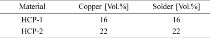
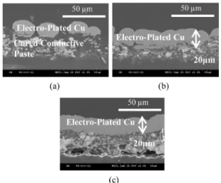
Abstract: An electro-plating technology on a cured isotropic conductive pattern with a hybrid Cu paste composed of resin matrix, copper, and solder powders has been developed. In a conventional technology, Ag paste was used to perform a conductive pattern on a PCB or silicon substrate. From previous research, the electrical conductive mechanism and prin- ciple of the hybrid Cu paste were concisely investigated. The isotropic conductive pattern on the PCB substrate was per- formed using screen-printing technology. The optimum electro-plating condition was experimentally determined by processing parameters such as the metal content of the hybrid Cu paste, applied current density, and time for the electro- plating in the plating bath. The surfaces and cross-sections were observed using optical and SEM photographs. In con- clusion, the optimized processing conditions for Cu electro-plating technology on the conductive pattern were a current density of 40mA/cm

2

and a plating time of 20min on the hybrid Cu paste with a metal content of 44 vol.%. More details of the mechanical properties and processing conditions will be investigated in further research.

Keywords: electro-plating Cu, hybrid Cu paste, isotropic conductive adhesive

1. Introduction

For the building process of a conductive pattern on sub- strates such as silicon and printed circuit boards (PCBs), electroplating technologies after the screen printing process are widely used for cost reduction and high reliability [1], [2]. Mette introduced an electro-plating technology with silver on cured silver paste performed using a screen print- ing method for silicon solar cells [1]. To reduce the contact resistance between silver pastes including glass frit and a silicon solar wafer, the silver is electro-plated on the sur- face of the printed silver and silicon substrates. From this technology, the contact resistance was reduced from 1×

10

−3

Ω cm

2

to 2×10

−7

Ω cm

2

.

1)

Nguyen et al. reported the effect of electro-plated Ni and Cu on the surface of silver paste to decrease the contact resistivity and increase the fill factor.

2)

A line resistivity of 1.75 µΩ-cm, which is very close to that of bulk Cu 1.70 µΩ-cm, was achieved using the electroplated Ni-Cu method.

2)

In previous research,

3)

hybrid Cu paste (HCP) as an iso-

tropic conductive paste (ICP) composed of metal powder and polymer resin was successfully developed. After cur- ing process of conductive pattern with HCP, it is observed that metal particles are randomly exposed on the surface of conductive layer and other area is covered by cured resin.

An electrical resistance of interconnection between con- ductive layer and an electrical device is strongly dependent on the exposed metal particles of the conductive layer.

Therefore, the contact resistance between the conductive layer of HCP and an electrical device will be relatively higher than another interconnection material such as solder paste. For the lower electrical resistance of interconnection between conductive layer and electrical device, an electro- plating process on the surface of conductive layer with HCP is required. HCP is composed of copper and solder powders with a resin matrix, including a fluxing function to remove the oxide. The electrical interconnection mecha- nism of HCP was characterized through the measurement of differential scanning calorimetry (DSC) and the electri- cal resistance. To reduce cost, HCP material processed

Corresponding author E-mail: [email protected]

© 2015, The Korean Microelectronics and Packaging Society

This is an Open-Access article distributed under the terms of the Creative Commons Attribution Non-Commercial License(http://creativecommons.org/

licenses/by-nc/3.0) which permits unrestricted non-commercial use, distribution, and reproduction in any medium, provided the original work is

properly cited.

(2)

52 Yong-Sung Eom, Ji-Hye Son, Hak-Sun Lee, Kwang-Seong Choi, Hyun-Cheol Bae, Jeong-Yeol Choi, Tae-Sung Oh and Jong-Tae Moon

마이크로전자 및 패키징학회지 제22권 제1호 (2015)

below 200

o

C was developed to substitute the high-cost Ag paste.

At the beginning the present research, the resin matrix based on epoxy to effectively remove oxide without the use of a conventional flux

3-9)

was investigated. In addition, instead of the Ag paste used in,

9)

HCP was finally devel- oped and used to perform a conductive pattern. Figure 1 shows the structure of the electrical conductive pattern with electroplated Cu on the HCP. First, the conductive pattern is performed using a screen printing method with HCP material, as shown in Fig. 1, and is cured under the given processing conditions. Copper is then electroplated on the surface of the cured conductive paste fabricated with HCP material.

Figure 2 shows a schematic of the electrical interconnec- tion mechanism of a conductive pattern with hybrid Cu paste. The screen-printed conductive pattern with HCP material is shown in Fig. 2(a) before application of the cur- ing process. It can be assumed that the copper flakes and solder powder are homogeneously dispersed in the resin matrix. With an increase in the processing temperature, the solder particles are melted and can be freely wetted to the adjacent Cu flakes, as the resin matrix is still in a liquid

state. The electrical passage indicated by the red arrow in Fig. 2(b) is then completely formed. The processing tem- perature is increased again to the curing temperature to obtain a complete curing state of the resin matrix. The interconnection mechanism of HCP was clearly investi- gated in previous research.

9)

Recently, it was reported that Ag-coated Cu flake as a filler was used for isotropic con- ductive paste.

10)

It is believed that the isotropic conductive pattern with Ag-coated Cu flake can be used for an electro- plating process in the near future.

2. Materials and Experimental

2.1. Materials

As shown in Table 1, there are two kinds of HCP, HCP-1 and HCP-2, with metal contents of 32 and 44 vol.%, respectively.

9)

The resin matrix of HCP material is mainly composed of epoxy, a curing agent, a reductant, and some additives. The average diameters of the conductive parti- cles used, such as copper flakes and Sn/58Bi solder pow- der, are about 5µm. The melting temperature of Sn/58Bi solder is 138

o

C. For the screen printing process, 20 mm×

20 mm non-conductive PCB with a thickness of 0.2 mm was used. For the electroplating process, a typical current source was used for applying a constant current.

2.2. Experiment

Figure 3 shows some schematic drawings of the screen- ing-printing and Cu electroplating processes on a PCB sub- strate. To perform a conductive pattern on a PCB substrate, HCP material was printed using a screen printing method at a dimension of 10 mm×10 mm, and cured at 180

o

C for 10 min on a hot plate, as shown in Fig. 3(a). Before the Cu electro-plating process, one-half (5 mm×10 mm) of the conductive pattern was covered by masking tape to prevent the electro-plating of Cu, as shown in Fig. 3(b). For the Cu electro-plating, the sample shown in Fig. 3(b) was immersed in a plating liquid, and a constant direct electric current (DC) was applied for a given period of time. After the Cu electro-plating process, the electro-plated sample was cleaned with water and the masking tape was removed. The applied density of the current and the time used for electro-plating were 20 and 40 mA/cm

2

, and 10 Fig. 1. Structure of the electrical conductive pattern with electro-

plated Cu on cured HCP: (a) surface and (b) cross-sectional views.

Fig. 2. Schematic of electrical interconnection mechanism of con- ductive pattern with hybrid Cu paste: (a) before and (b) after the curing process.

Table 1. HCP materials used for screen printing as an isotropic conductive paste

Material Copper [Vol.%] Solder [Vol.%]

HCP-1 16 16

HCP-2 22 22

(3)

Development of Copper Electro-Plating Technology on a Screen-Printed Conductive Pattern with Copper Paste 53

J. Microelectron. Packag. Soc. Vol. 22, No. 1 (2015) and 20 min, respectively. For an inspection of the electro-

plated Cu, surface and cross-sectional views were observed using a scanning electron microscope (SEM).

3. Results and Discussion

Figure 4 shows photographs taken by an optical micro- scope. A conductive pattern with a dimension of 10mm x 10mm was performed through the screen printing and cur- ing process conducted at 180

o

C for 10 min on the hot plate, as shown in Fig. 4(a). The average thickness of the conduc- tive pattern for the HCP-1 and HCP-2 materials was mea- sured to be about 30 µm. The average electrical resistances of HCP-1 and HCP-2 between points A and B in Fig. 3(a) were about 4.0 and 2.0 ohm, respectively. As expected, the HCP-2 material with a high metal content of Cu 22 vol.%

and solder content of 22 vol.% shows lower electrical resistance than HCP-1, with a Cu content of 16 vol.% and solder content of 16 vol.%. Figure 4(b) shows an optical photograph taken after a 10-min Cu electro-plating process with a current density of 40 mA/cm

2

. The pink area indi-

cates the electro-plated Cu, while the dark brown color indicates the cured conductive paste of the HCP materials.

Figure 5 shows SEM photographs of the surfaces of the electro-plated Cu and the cured conductive paste itself. The light gray grainy area is the electro-plated Cu, while the dark gray area is the bare conductive paste. To determine the optimum electro-plating condition, different electrical current densities and metal contents of the HCP materials were used with a constant electro-plating time in a plating bath. For the conductive patterns of HCP-1 with 16 vol.%

Cu and 16 vol.% solder in Fig. 5, different electrical cur- rents of 20 and 40 mA/cm

2

were applied for 10 min, as shown in Figs. 5(a) and 5(b), respectively. In these figures, it can be seen that a higher current density shows a more compact electro-plated Cu for a constant metal content of the HCP material. In Fig. 5(c) and 5(d), current densities of 20 and 40 mA/cm

2

were used for 10 min for HCP-2 with a high metal content of 22 vol.% Cu and 22 vol.% solder.

Figures 5(a) and 5(c) show a comparison of different metal contents with HCP under the same electro-plating condi- tion. It can be clearly seen that the speed of the electro- plating is increased with an increase in the metal contents in the HCP material.

Figure 6 shows cross-sectional SEM photographs of an electro-plated Cu layer on a cured HCP layer with different electro-plating conditions and HCP materials. Figures 6(a) and 6(b) show photographs of the HCP-1 and HCP-2 mate- rials, respectively, after the same electro-plating at 40 mA/

cm

2

for 10 min. A light-gray electro-plated Cu layer with an uneven shape can be seen in Figs. 6(a) and 6(b). As shown in the figures, however, the density of the electro- Fig. 3. Schematic drawings of screen-printing and Cu electroplat-

ing processes on a PCB substrate: (a) after the screen-print- ing and curing processes, (b) before electroplating with masking tape attached to the conductive pattern, and (c) after Cu electroplating on the conductive pattern.

Fig. 4. Conductive patterns (a) before and (b) after Cu electro-plat- ing.

Fig. 5. SEM photographs with the surfaces of electro-plated Cu for

10min. and cured Cu pastes: (a) HCP-1 with a current den-

sity of 20 mA/cm

2

, (b) HCP-1 with a current density of 40

mA/cm

2

, (c) HCP-2 with a current density of 20 mA/cm

2

and (d) HCP-2 with a current density of 40 mA/cm

2

.

(4)

54 Yong-Sung Eom, Ji-Hye Son, Hak-Sun Lee, Kwang-Seong Choi, Hyun-Cheol Bae, Jeong-Yeol Choi, Tae-Sung Oh and Jong-Tae Moon

마이크로전자 및 패키징학회지 제22권 제1호 (2015)

plated Cu grains of HCP-2 with a high metal content was higher than that of HCP-1 with a low metal content. Fig- ures 6(b) and 6(c) show SEM photographs of electro- plated Cu on HCP-2 with a current density of 40 mA/cm

2

for 10 and 20 min, respectively. The average thickness of the electro-plated Cu layer in both Figs. 6(b) and 6(c) is about 20 µm, although the electro-plated Cu density of Fig.

6(b) is lower than that of Fig. 6(c). As shown in Fig. 6(c), the surface of the electro-plated Cu layer with an average thickness of 20 µm is relatively smoother than in the other samples. Therefore, it is concluded that the optimum con- dition of the Cu electro-plating process for HCP-2 material is 40 mA/cm

2

for 20 min.

From the present research, instead of a pre-existing Ag paste, the possibility of Cu electro-plating on a hybrid Cu paste was clearly confirmed. As a competitively priced iso- tropic conductive paste, hybrid Cu paste can be a good candidate. The process and material reliability such as adhesion strength, solder wetting, and mechanical proper- ties of electro-plated Cu will be investigated in the near future for industrial application.

4. Conclusion

For a competitively priced isotropic conductive paste, a technology for Cu electro-plating on a low-cost hybrid Cu paste was developed. The process of Cu electro-plating on the hybrid Cu paste was investigated experimentally through the optimization of the metal content of HCP material, applied current density, and electro-plating time. As future research, the mechanical properties of an electro-plated Cu

layer and the soldering process on its surface will be opti- mized.

Acknowledgements

This work was supported by KEIT, IT R&D program of Daeduck Innoplis Foundation [The commercialization of Ag coated Cu paste material with low melting point], the R&D program of ISTK [Development of an image-based, real-time inspection and isolation system for hyperfine faults], the R&D Convergence Program of NST [National Research Council of Science & Technology] of Republic of Korea and Electronics and Telecommunications Research Institute.

References

1. A. Mette, “New Concepts for Front Side Metallization of Industrial Silicon Solar Cells”, Ph.D Thesis, Fraunhofer-Insti- tute for Solar Energy System, Freiburg im Breisgau, Germany (2007).

2. A. Nguyen, A. Fioramonti, D. Morrissey, H. Efstathiadis, Z.

Zhouying and P. Haldar, “Feasibility of Improving Front Met- allization Lines for Photovoltaic Devices”, Proc. 34

th

Photo- voltaic Specialists Conference (PVSC), Philadelphia, PA, 000312, IEEE (2009).

3. Y. S. Eom, J. W. Baek, J. T. Moon, J. D. Nam and J. M. Kim,

“Characterization of Polymer Matrix and Low Melting Point Solder for Anisotropic Conductive Film”, Microelectron.

Eng., 85(2), 327 (2008).

4. Y. S. Eom, K. S. Jang, J. T. Moon, J. D. Nam and J. M. Kim,

“Electrical and Mechanical Characterization of an Anisotro- pic Conductive Adhesive with a Low Melting Point Solder”, Microelectron. Eng., 85(11), 2202 (2008).

5. Y. S. Eom, K. S. Jang, J. T. Moon and J. D. Nam, “Electrical Interconnection with a Smart ACA Composed of Fluxing Polymer and Solder Powder”, ETRI J., 32(3), 414 (2010).

6. J. W. Baek, K. S. Jang, Y. S. Eom, J. T. Moon, J. M. Kim and J. D. Nam, “Chemo-rheological Characteristic of a Self- assembling Anisotropic Conductive Adhesive System Con- taining a Low-Melting Point Solder”, Microelectron. Eng., 87(10), 1968 (2010).

7. K. S. Jang, Y. S. Eom, J. T. Moon, Y. S. Oh and J. D. Nam,

“Catalytic Behavior of Sn/Bi Metal Powder in Anhydride- Based Epoxy Curing”, J. Nanosci. Nanotechnol., 9(12), 7461 (2009).

8. K. S. Choi, K. J. Sung, B. O. Lim, H. C. Bae, S. H. Jung, J. T. Moon and Y. S. Eom, “Novel Maskless Bumping for 3D integration”, ETRI J., 32(2), 342 (2010).

9. Y. S. Eom, K. S. Choi, S. H. Moon, J. H. Park, J. H. Lee and J. T. Moon, “Characterization of a Hybrid Cu Paste as an Iso- tropic Conductive Adhesive”, ETRI J., 33(6), 864 (2011).

10. G. H. Kim, K. M. Jung, J. T. Moon and J. H. Lee, “Electrical Resistivity and Thermal Conductivity of Paste Containing Ag-coated Cu Flake Filler”, J. Microelectron. Packag. Soc., 21(4), 51 (2014).

Fig. 6. SEM photographs of the cross-sections of electro-plated Cu

on cured Cu pastes: (a) HCP-1 with a current density of 40

mA/cm

2

for 10 min, (b) HCP-2 with a current density of

40 mA/cm

2

for 10 min, and (c) HCP-2 with a current den-

sity of 40 mA/cm

2

for 20 min.

수치

Fig. 2. Schematic of electrical interconnection mechanism of con- con-ductive pattern with hybrid Cu paste: (a) before and (b) after the curing process.
Figure 4 shows photographs taken by an optical micro- micro-scope. A conductive pattern with a dimension of 10mm x 10mm was performed through the screen printing and  cur-ing process conducted at 180 o C for 10 min on the hot plate, as shown in Fig
Fig. 6. SEM photographs of the cross-sections of electro-plated Cu on cured Cu pastes: (a) HCP-1 with a current density of 40 mA/cm 2  for 10 min, (b) HCP-2 with a current density of 40 mA/cm 2  for 10 min, and (c) HCP-2 with a current  den-sity of 40 mA/c

참조

관련 문서

However, all greetings are usually used to welcome people and wish them

 The Dutch physicist Pieter Zeeman showed the spectral lines emitted by atoms in a magnetic field split into multiple energy levels...  With no magnetic field to align them,

Modern Physics for Scientists and Engineers International Edition,

Purpose: The purpose of this research was to study the influences of a floortime-based sensory integration program on both initial and reaction behaviors

첫째, UTAUT모형을 이용하여 스마트폰 어플리케이션의 구매에 대해 검정한 결과 독립변수들 (성과기대, 예상노력, 사회적 영향, 유희적 가치,

Since every classical or virtual knot is equivalent to the unknot via a sequence of the extended Reidmeister moves together with the forbidden moves, illustrated in Section 2,

웹 표준을 지원하는 플랫폼에서 큰 수정없이 실행 가능함 패키징을 통해 다양한 기기를 위한 앱을 작성할 수 있음 네이티브 앱과

The “Asset Allocation” portfolio assumes the following weights: 25% in the S&P 500, 10% in the Russell 2000, 15% in the MSCI EAFE, 5% in the MSCI EME, 25% in the