Superconductivity and Cryogenics Vol.12, No.2, (2010), pp.13~16
```
Abstract-- The superconducting synchronous motor or generator mostly has high permeability iron only around outer yoke portion. Therefore, if excitation voltage (Back E.M.F) is calculated from 2 dimensional magnetic field distributions, it can be largely different from actual value due to additional voltage originated from end coils. In order to calculate the excitation voltage more accurately, 3 dimensional magnetic field calculation is necessary for including the end coil effect from large air-gap structure. The excitation voltage can be calculated by stator (armature) coil linkage flux originated from rotor (field) coil excitation, but it is difficult to calculate the flux linkage exactly because of complicated structure of the stator coil. This paper shows a method to calculate the excitation voltage from 3 dimensional magnetic energy that can be calculated directly from volume integration of magnetic flux density and field intensity scalar product through FEM (Finite Element Method) analysis software.
1. INTRODUCTION
Excitation voltage is induced at the armature coils of a synchronous rotating machine by rotating magnetic field of field coil and does an important role in output characteristics of a synchronous rotating machine. Most part of general motors and generators consists of iron core which has high permeability so makes magnetic flux pass easily through it. Therefore, most conventional rotating machines have very small air-gap separating between rotor and stator about 1 mm to reduce reluctance of magnetic flux path. Due to the small air-gap 2 dimensional electromagnetic analysis result is very accurate compared with experimental one. By the way the superconducting synchronous rotating machine has no magnetically high permeable material in the rotor and very large air gap between the rotor and the stator. So it needs 3 dimensional electromagnetic analysis to get accurate result. Several papers dealt with 3 dimensional magnetic field analysis of a superconducting synchronous rotating machine in early 90’s. Those papers, however, were just focused on magnetic field calculation, so that it is not enough to evaluate machine output performances [1, 2].
This paper describes a calculation method of the excitation voltage of a superconducting rotating machine through
through magnetic stored energy calculation after major machine parameters such as self and mutual inductances of armature and field coils are calculated by 3 dimensional electromagnetic FEM tool. In order to calculate excitation voltage, ordinary method with FEM tool has to rotate rotor coil, which results in longer calculation time, but this method does not need to rotate the rotor.
2. THEANALYSISANDTESTMACHINE The developed HTS synchronous machine is composed of Bi-2223 HTS field coils cooled by conduction heat transfer of liquid neon and copper armature coils cooled by water passing through them. The Fig. 1 shows the construction of the developed 1 MW HTS synchronous machine and the Table 1 shows the major specifications.
Fig. 1. Construction of the developed 1 MW HTS synchronous machine.
Electrical Parameter Evaluation of 1 MW HTS Motor via Magnetically Stored Energy Calculation
Seung-Kyu Baik1,*, Young-Kil Kwon1, Ho-Min Kim1, Jae-Deuk Lee1, and Yeong-Chun Kim2
1Korea Electrotechnology Research Institute, Changwon, Kyungnam 641-120, Korea
2Doosan Heavy Industries & Construction Co., LTD., Changwon, Kyungnam 641-792, Korea
Received 23 March 2010; accepted 6 May 2010
* Corresponding author: [email protected]
TABLEI
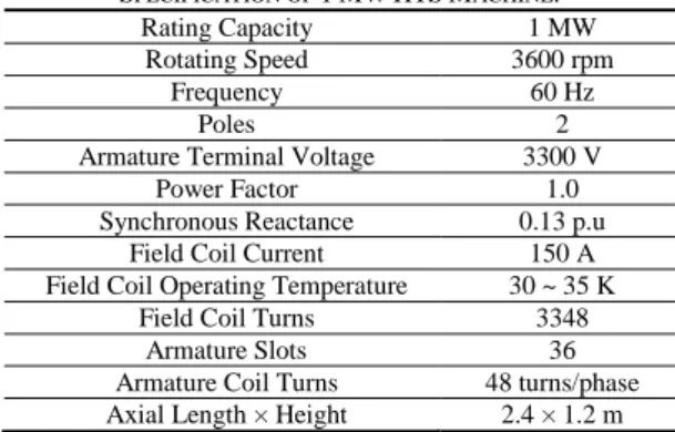
SPECIFICATION OF 1MWHTSMACHINE.
Rating Capacity 1 MW
Rotating Speed 3600 rpm
Frequency 60 Hz
Poles 2
Armature Terminal Voltage 3300 V
Power Factor 1.0
Synchronous Reactance 0.13 p.u
Field Coil Current 150 A
Field Coil Operating Temperature 30 ~ 35 K
Field Coil Turns 3348
Armature Slots 36
Armature Coil Turns 48 turns/phase Axial Length × Height 2.4 × 1.2 m
Electrical Parameter Evaluation of 1 MW HTS Motor via Magnetically Stored Energy Calculation
Liquid neon is supplied from outside of the rotor through a long stainless steel pipe connected to a cold head of a GM cryocooler which liquefies gas neon evaporated from inside of the rotor. This 2 phase closed loop cooling mechanism is called thermosiphon that has been applied to several HTS motors developed worldwide [3, 4].
3. EXCITATION VOLTAGE CALCULATION 3.1. Excitation Voltage Calculation Procedure through
3D Magnetic Field Analysis
Excitation voltage is induced voltage at armature coil of a synchronous rotating machine by rotation of field coil and can be calculated by well-known Faraday’s law as shown in (1) [5]. So in order to estimate the excitation voltage waveform, it is necessary to calculate time-varying armature flux linkage due to the rotating magnetic field of rotor. However, it is difficult to get the waveform because the flux linkage must be calculated at each time step depending on the rotor position and it takes lots of time to calculate the waveform especially through 3 dimensional magnetic field analysis. But if the excitation voltage is so sinusoidal as in a conventional machine with well-distributed or in a superconducting machine with air-cored armature coils, its rms (root mean square) value can be calculated accurately with maximum flux per armature pole produced by field coil from (2) [6]. The electrical parameters of a conventional synchronous machine such as flux linkage and inductance can be calculated accurately by way of 2 dimensional magnetic field calculation. However, in case of the superconducting synchronous machine, air gap between field and armature is very large compared with the conventional synchronous rotating machine. Therefore, flux linkage and inductance due to coil end parts of field and armature is very large compared with the conventional machine having very small air gap, so 3 dimensional magnetic field calculation is necessary to calculate the excitation voltage accurately.
By the way, it is difficult to calculate the flux linkage of the armature coil 3 dimensionally due to its complicated shape.
But if we can calculate maximum mutual inductance between field and armature coils, the rms value of excitation voltage can be calculated from (3) based on an assumption that the excitation voltage waveform is sinusoidal [6].
dt Nd dt Nd
emf (1)
where, N is turn number of a coil, Φ is flux passing through any one of N coincident paths, and λ = NΦ is flux linkage of a coil.
af ph w
af fk N
E 2 (2)
where, f is the frequency in hertz, kw is a reduction factor of distributed armature coil, Nph is the number of series turns
per armature phase, and Φaf is maximum flux per armature pole produced by the field coil.
2
max f af af
I E M
(3)
where, ω is the angular frequency in rad/sec, If is field coil current, and Mafmax is maximum mutual inductance between field and armature coils.
a f af a f
total W W M I I
W (4)
where, Wtotal is stored energy by all coil excitation, Wf is stored energy by only field coil excitation, Wa is stored energy by only armature coil excitation, Maf is mutual inductance between field and armature coils, and Ia is armature coil current.
dv H B
W 21vol (5)
In this paper the maximum mutual inductance in (3) is calculated from (4) for this superconducting synchronous machine system with two pairs of electric terminals [4].
Each stored energy of (4) is calculated from (5) in the magnetic field produced by coil excitation [5].
3.2. Excitation Voltage Calculation of 1 MW HTS Machine through 3D Magnetic Field Analysis In order to calculate the magnetic stored energy, a 3 dimensional FEM tool has been used, which is called OPERA-3D [7]. As shown in Fig. 2 the 1 MW HTS machine was modeled and meshed with OPERA-3D. At first magnetically stored energy was calculated from 3 dimensional magnetic field distribution when only HTS field coil is excited with DC 150 A, rating current. The magnetically stored energy, Wf, is calculated by the volume integration of (5), which is 34,651 J, and the self-inductance of the HTS field coil of the developed 1 MW machine can be calculated from (6), which is 3.08 H [5].
2
2 I
L W (6)
where, W is the stored energy by a coil excitation, and I is the coil excitation current.
Secondly stored energy, Wa, was calculated when only armature coil is excited with DC 181 A same with AC rms design rating current, which is 30.96 J derived from (5). As the same way, from (6), the self-inductance of one phase armature coil is 1.88 mH. The armature coil was modeled with only one phase positioned to get maximum mutual inductance with the field coil. Finally 3 dimensional 14
Seung-Kyu Baik, Young-Kil Kwon, Ho-Min Kim, Jae-Deuk Lee, and Yeong-Chun Kim
magnetic
Fig. 2. 3 dimensional finite element analysis model of the 1 MW HTS synchronous machine.
magnetic field distribution was calculated when both the field and the armature coils are excited with DC 150 A and DC 181 A of the rating currents respectively. At this time the magnetic stored energy, Wtotal, was also calculated by the volume integration of (5), which is 35,859 J, and then the mutual inductance, Maf, between the field and armature coils was calculated from (4), which is 43.24 mH [3].
Because Maf is the maximum mutual inductance, the armature phase excitation voltage, Eaf, is 1729 Vrms from (3).
4. COMPARISON WITH TEST RESULTS
Fig. 3. Experimental set-up of the developed 1 MW HTS synchronous machine.
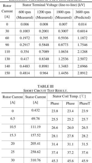
Fig. 3 shows the developed 1 MW HTS synchronous motor coupled to a 1.1 MW induction machine for test. In order to get the basic parameters such as mutual inductance and excitation voltage, three phase armature coils are open-circuited and the induced terminal voltages (excitation voltages) are measured while the field current and the rotor speed vary. The results are shown as OCC (Open Circuit Characteristics) curves in Fig. 4 at each different field current and rotor speed. The measured excitation voltages are three phase line-to-line terminal voltages and directly proportional to the rotor speed, so to
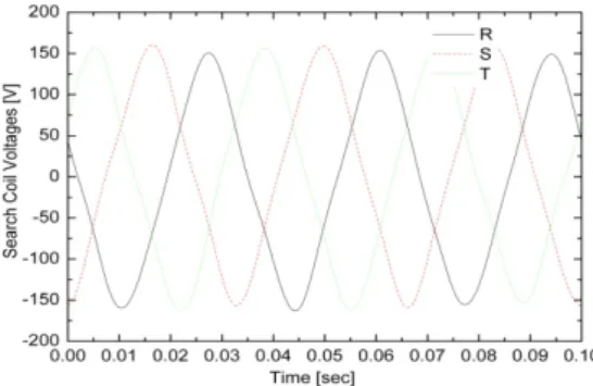
speak, the angular frequency in (3). The line-to-line excitation voltage from OCC test is 2891 Vrms at 150 A of field coil rating current and 3600 rpm rating speed, which is 1669 Vrms phase voltage. The phase excitation voltage at the same condition is 1729 Vrms from the 3D magnetic field calculation in section 3, so the error is 3.59 %, which seems to come mainly from the fact that the measured value indicates only fundamental component and the analysis rms value was calculated based on the assumption that the excitation voltage is sinusoidal. Actually the measured excitation voltage is very sinusoidal as shown in Fig. 5 because there are non-magnetic FRP (Fiber Reinforced Plastic) armature teeth instead of iron teeth to support the armature coils.
The developed 1 MW machine shows non-saturated (straight) OCC curves as shown in Fig. 4 because no ferro-magnetic material (iron) is used in the rotor and for the armature teeth. However, in case of the conventional iron-cored synchronous machine, the excitation voltage is saturated due to iron-core saturation as the field current increases [4]. From the OCC test result, the maximum mutual inductance between the armature and the field coils can be calculated from (3), which is 41.74 mH. The calculated maximum mutual inductance from the section 3 is 43.24 mH, which has also 3.59 % error from the measured value.
TABLEII
EXCITATION VOLTAGES OF 1MWHTSMACHINE. Rotor
Current [A]
Stator Terminal Voltage (line-to-line) [kV]
600 rpm (Measured)
1200 rpm (Measured)
1800 rpm (Measured)
3600 rpm (Predicted)
0 0.006 0.008 0.007 0.014
30 0.1003 0.2001 0.3007 0.6014
60 0.1972 0.395 0.5936 1.1872
90 0.2917 0.5848 0.8773 1.7546
110 0.354 0.7089 1.0634 2.1268
130 0.417 0.8348 1.2536 2.5072
140 0.4483 0.8981 1.3483 2.6966
150 0.4814 0.964 1.4456 2.8912
TABLEIII SHORT CIRCUIT TEST RESULT. Rotor Current
[A]
Stator Current [A]
Stator Coil Temp. [℃]
Phase Phase PhaseT
0 0.432 23.8 23.4 23.9
6.5 69.76 25.5 25.2 25.7
10.5 111.19 26.6 26.0 26.5
15.3 157.52 28.1 27.8 28.2
20 205.41 31.4 31.1 31.5
25 258.62 37.4 37.2 37.6
30 310.76 45.3 45.6 45.9
15
Electrical Parameter Evaluation of 1 MW HTS Motor via Magnetically Stored Energy Calculation
Fig. 4. Armature open circuit (OCC) and short circuit (SCC) test result.
Fig. 5. Measured excitation voltage waveforms from search coils (6 turns/phase) at 1800 rpm.
2 sc 2
I
s ph
af
X R
E
(7)
where, Isc is the armature coil short circuit current during SCC test, Eaf is the excitation voltage per phase during SCC Test, Rph is armature coil resistance per phase, and Xs is synchronous reactance.
During the Short Circuit Characteristics (SCC) test, the armature coils are three phase short-circuited. The short circuit current is related with other parameters as (7). The excitation voltage, Eaf, is 173.6 V per phase measured from OCC test and the short circuit current, Isc, is 310.8 A measured from the SCC test with the same field current of 30 A and rotor speed of 1800 rpm and the armature coil resistance per phase, Rph, is 0.0965 Ω measured at 20℃.
By using these parameters the synchronous reactance, Xs, is 0.5502 Ω at 1800 rpm, so the synchronous inductance, Ls, can be calculated from (8), which is 2.92 mH. Then the synchronous reactance at the rating speed of 3600 rpm is 1.1008 Ω, which is calculated from (8) by substituting 2 times of the angular frequency, ω, at 1800 rpm [8].
s
X
Ls (8)
5. CONCLUSION
A superconducting synchronous motor or generator does not use ferromagnetic material besides machine shield which plays the same role with iron yoke of a conventional rotating machine. A conventional rotating machine has very small gap between stator and rotor, so the excitation voltage calculated from 2 dimensional magnetic field analysis has small error to the actual value.
However, because a superconducting rotating machine is iron-coreless structure, the excitation voltage calculated from 2 dimensional magnetic field calculation has large error to the actual value.
A 1 MW class HTS synchronous machine has been developed and tested. Some major parameters such as self and mutual inductances and excitation voltage were calculated from 3D magnetic field analysis and within 5%
error compared with the test results. The excitation voltage was calculated from maximum mutual inductance between the field and the stator coils through magnetic stored energy calculation without rotating HTS field coil. So this method is able to reduce calculation time of excitation voltage very much through 3 dimensional magnetic field analysis of a superconducting synchronous rotating machine.
ACKNOWLEDGMENT
This research was supported by a grant from Center for Applied Superconductivity Technology of the 21st Century Frontier R&D Program funded by the Ministry of Science and Technology, Republic of Korea.
REFERENCES
[1] B. Bodner, H. Kofler, and J. Sammer, “3-dimensional Magnetic Field Calculation for an Arrangement of S.C. Coils with an Outer Magnetic Core”, IEEE Trans. Magnetics, vol. 28, NO. 2, pp.
1402–1405, 1992.
[2] L. J. Laslett, S. Caspi, M. Helm, and V. Brady, “Three-Dimensional Magnetic Field Produced by an Axisymmetric Iron Yoke”, IEEE Trans. Magnetics, vol. 28, NO. 1, pp. 946–948, 1992.
[3] S. S. Kalsi, K. Weeber, H. Takesue, C. Lewis, H.-W. Neumueller, and R. D. Blaugher, “Development Status of Rotating Machines Employing Superconducting Field Windings”, Proceedings of the IEEE, vol. 92, NO. 10, pp. 1688–1704, 2004.
[4] M. Frank, J. Frauenhofer, P. van Hasselt, W. Nick, H.-W.
Neumueller, and G. Nerowski, “Long-Term Operational Experience with First Siemens 400 kW HTS Machine in Diverse Configurations”, IEEE Trans. Applied Superconductivity, vol. 13, pp. 2120–2123, 2003.
[5] William H. Hayt, Jr., “Engineering Electromagnetics”, McGRAW-HILL International Editions, 5th Edition, pp. 297-313, 1989.
[6] A. E. Fitzgerald, Charles Kingsley, Jr., and Stephen D. Umans,
“Electric Machinery”, McGRAW-HILL International Editions, 5th Edition, pp. 114-229, 1991.
[7] “OPERA-3D REFERENCE MANUAL and USER GUIDE”, Vector Fields Limited, Version 8.0, 2001.
[8] IEEE Guide: Test Procedures for Synchronous Machines (IEEE Std 115-1995), The Institute of Electrical and Electronics Engineers Inc., New York, pp. 27-38, 1995.
16