Vol. 19, No. 6, pp. 54-59, December 2015
Orifice Type의 유압실린더 유동해석에 관한 연구
Study on the hydraulic cylinder flow analysis of Orifice Type
배강열*․전진성**†
Kang-Youl Bae* and Jin-Seong Jeoun**†
(Received 13 August 2015, Revision received 08 December 2015, Accepted 09 December 2015)
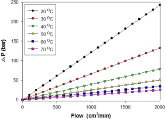
Abstract: This paper is a numerical study on the correlation of leakage by the variation of operating temperature and orifice diameter applying to hydrostatic bearing in hydraulic actuator. Compared with Brackbill and Kandlikar experimental paper to verify the validity of the numerical analysis technique of the present study, we derive the result that the results of experiments and numerical analysis to match very well. CFD analysis program were analyzed using a commercial code FLUENT V14.5. Inlet and outlet, were applied pressure conditions, the main variables of the analysis is temperature and the orifice inner diameter. The analysis results, pressure value has decreased as the oil temperature and the orifice diameter increases.
Key Words:Orifice, Pressure difference, Hydraulic cylinder, CFD(Computational fluid dynamics), Leakage Rate
**
†
전진성(교신저자) : (주)대명지이엔티E-mail : [email protected], Tel : 051-323-8202
*배강열 : (주)대명지이엔티
**
†
Jin-Seong Jeoun(corresponding author) : Dae Myung GENT Co., Ltd.E-mail : [email protected], Tel : 051-323-8202
*Kang-Youl Bae : Dae Myung GENT Co., Ltd.
1. 서 론
최근 유압실린더(Hydraulic cylinder)는 대형 기 계들의 사용이 증가하고, 이러한 대형 기계들의 정밀한 제어에 대한 요구가 증가됨에 따라 그 사 용이 날로 증가하고 있는 실정이다
1). 특히, 제품 의 품질 기준이 높은 발전소(원자력, 화력)들에서 사용되는 유압 실린더는 거의 전량 수입에 의존 하고 있는 실정이기 때문에 제품의 보수 및 교체 에도 많은 어려움이 있으며, 해외 업체의 부품 생 산중단에 의한 부품 조달의 어려움도 수시로 발 생되고 있는 실정이다
2). 또한 기존의 유압실린더
의 경우, 내부 피스톤과의 접촉 부위가 Seal 형태
로 되어있어 표면마찰에 따른 열마모 발생 및 습
동저항에 의해 정밀제어가 불가능할 뿐만 아니라,
내구성이 저하되어 2년 주기로 대부분 교체하고
있는 상황이다. 이러한 제품의 짧은 수명주기 때
문에 발전소 시스템의 효율성이 저하된다는 문제
점이 지적되고 있다. 오리피스형(Orifice type)의
정압베어링은 기존방식의 문제점인 습동 저항 현상
을 해결할 수 있다. 따라서 본 연구에서는 오리피
스형(Orifice type)에 대한 실험 및 유동해석을 진행
하여 오리피스 직경변화 및 온도에 따른 압력변화
를 도출하여 실제 산업현장 적용에 목적이 있다.
2. 수치해석 기법 검증
본 연구를 위해 Brackill과 Kandlikar
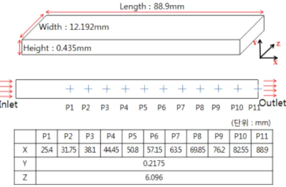
3)의 좁은 사 각채널에서 길이방향의 압력값 실험 결과와 동일 한 조건을 적용한 수치해석 기법에 대한 비교검 증을 실시하였다. 적용유체 및 유체온도는 실험과 같은 조건인 물 26.6°C를 사용하였고, 입구는 유 량경계조건, 출구는 압력경계조건을 적용하였다.
정상상태(Steady-state)의 층류유동(Laminar flow)해 석을 진행하였다. Fig. 1은 실험 및 해석 모델, 압 력값 측정위치를 나타내었다.
Fig. 1 Numerical model and pressure data point
실험과 수치해석 비교결과 최소 오차율 0.116%, 최대 오차율 0.542%로 결과가 매우 잘 일 치하고 있기 때문에 본 연구에 적용된 수치해석 기법의 타당성을 검증할 수 있었다. Fig. 2는 실험 과 수치해석의 각 지점에 대한 압력값을 비교한 그래프이다.
Fig. 2 Comparison of pressure data between experimental and numerical results
3. Mock-Up 실험
Fig. 3은 증기 터빈밸브 작동용 유압실린더의 개념도를 나타내었다. 실제 제작 모델인 5inch, 10inch 모델에 앞서 모형(Mock-up)모델을 제작하 여 실험하였다. 실험환경조건은 상온 25℃, 작동 유체는 ISO VG 46 Oil을 사용하였다.
(a) Cylinder
(b) Hydrostatic Bearing Fig. 3 Hydraulic Valve Actuator
실린더 내경은 50.01mm, Rod 외경은 49.91mm 로 내경과 외경의 격차는 0.05mm로 설정하였다.
입구압력은 50bar로 설정하고, 출구에서 누설되는 누설량을 측정하였다. Fig. 4는 오리피스형 모형 (Orifice type Mock-up) 실험 장치를 나타내었다.
Fig. 4 Orifice type mock-up tester
4. 수치 해석
4.1 지배방정식
다음은 해석에서 사용된 지배방정식이다. 정상
유동, 비압축성 유동으로 가정하여 운동량 방정식
을 적용하였고, 점성소산 및 열전달은 고려하지
않기 때문에 에너지 방정식은 적용하지 않았다.
연속방정식(Continuity equation)
(1)
운동량방정식(Momentum equation)
X 방향 :
Y 방향 :
(2) Z 방향 :
여기에서 는 유체의 밀도, 는 동점성계수이 며, . 는 각각 방향의 속도 성분이다.
지배방정식의 해법을 위해서 ANSYS-FLUENT에 서 제공하는 공간차분은 2차 정확도의 상류도식 (Second order upwind)을 사용하였다. 수렴판정 조 건은 운동량 및 연속방정식의 Residual이 10
-3이 하일 때로 지정 하였다.
4.2 수치해석 모델 및 경계조건
전산유체역학해석을 위하여 상용 CAD 프로그 램인 CatiaV5R20을 이용하여 모델링하였다. 또한 범용 유동해석 프로그램인 Fluent V15를 사용하였 다. 초기경계 조건으로는 유체가 유입되는 입구에 유속을 입력할 수 있는 Velocity-inlet 조건을 사용 하고 유체의 출구에는 출구 압력을 입력할 수 있 는 Pressure-outlet 조건을 적용하였다. 유체의 점성 으로 인한 배관의 벽면과 유체 마찰은 No-slip 마 찰조건을 이용하여 고려하였다. 유체 유동은 정상 상태(Steady-state), 비압축성 층류 유동(Laminar flow)을 가정하였다. 유동해석에 이용된 요소망 생 성은 격자 생성 전용 프로그램인 Icem CFD를 이 용하였으며 사용된 총 요소 수는 약 210만개이다.
내부에 흐르는 유체는 각 온도에 따른 밀도 및 점
성을 설정하였다.
Fig. 5은 유압실린더와 정압베어링의 수치해석 모델을 나타낸 것이다. (a)에서 표시된 부분에 정 압베어링이 구성되며, 해석 시간 및 격자의 감소 를 위하여 (b)와 같이 대칭(Symmetry)조건을 이용 해 최소한의 해석영역을 설정하였다. (c)는 설정된 영역의 유동해석 부분을 나타내었다. Fig. 6은 유 동해석에 사용된 격자를 나타내었다.
(a) Hydrostatic bearing
(b) Simplification of the model
(c) Flow analysis area
Fig. 5 Numerical model of hydrostatic bearing
Fig. 6 Mesh of hydrostatic bearing
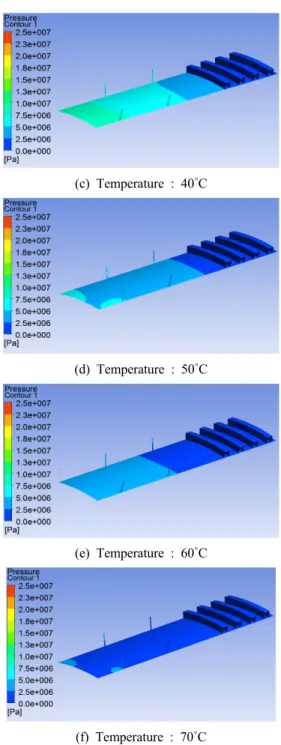
4.3 수치해석 결과