outer opening of the carotid canal present at the base of the triangular petrous temporal bone. The petrous part of ICA (P-ICA) is an obscure portion and is not readily accessible to observation/imaging [3-6]. The cavernous part of the ICA (C-ICA), also called parasellar ICA is in the form of a siphon which is twisted and torqued in three dimensions and sur- rounded by a network of veins. This section of the artery has broad biological and medical interest because of its peculiar shape and is associated with temperature regulation in the brain and correlated with the occurrence of vascular patholo- gies [7].
Atherosclerotic plaques are often located in C-ICA. Stud- ies indicate that the incidence of pre-atherosclerotic lesions is linked with the complexity of the C-ICA [8], but its shape has not been objectively characterized. There is paucity of litera- ture which provides characterization of the shape of ICA.
Introduction
The internal carotid arteries (ICA) and their major branch- es are referred to as internal carotid system. Anatomically the ICA is divided into extracranial and intracranial parts. The intracranial part is further subdivided into petrous, cavern- ous, and cerebral parts [1, 2]. Clinically they are described as anterior circulation of the brain. The internal carotid artery enters the cranium from the base of the skull through the
Corresponding author:
Manisha Vijaywargiya
Department of Anatomy, People's College of Medical Sciences and Research Centre, E-6/ 127 Arera Colony, Bhopal, Madhya Pradesh 462016, India
Tel: +91-07554208282, Fax: +91-07554208282, E-mail: [email protected]
Anatomical study of petrous and cavernous parts of internal carotid artery
Manisha Vijaywargiya
1, Rashmi Deopujari
1, Sunita Arvind Athavale
21Department of Anatomy, People's College of Medical Sciences and Research Centre, Bhopal, 2Department of Anatomy, All India Institute of Medical Sciences, Bhopal, India
Abstract: The petrous and cavernous parts of internal carotid artery (ICA) are obscure and are not readily accessible to observation/imaging. These parts have broad biological and medical interest because of their peculiar shape. Given the their clinical importance and the scarce data available based mostly on imaging, the present study was aimed at studying these parts of ICA by dissection. The study was carried out on 56 ICAs obtained from embalmed adult cadavers and 10 ICAs from five fetuses. The foetal ICAs were studied in situ. The morphometric analysis of the adult ICA was done after its removal from cranial cavity to gain an insight into the geometry of the vessel, i.e., length, various bends, and diameters at various locations.
ICAs in fetuses ran a relatively straighter course taking gentle curves at three positions (two intrapetrous, one cavernous). Adult ICAs were more tortuous and exhibited greater variability in length and angulations. The length of respective portions of the ICA correlate negatively with the measure of angles. The angles in the petrous and cavernous parts were positively correlated to each other. The carotid siphon was positively, highly significantly correlated to other angles. Longer vessels are more tortuous with acute bends. An acute carotid siphon is an indication of more tortuous ICA. The findings of the present study have created a reference data of unsuspected adult population and has potential implications for studying cause/effect relationship of vessel geometry and hemodynamic factors.
Key words: Angles, Cavernous segment, Length, Petrous segment
Received August 3, 2016; 1st Revised May 31, 2017; 2nd Revised June 10, 2017; Accepted July 12, 2017
The information about the occurrence, position, and size of intimal hyperplasia in the C-ICA is scant, and information about atherosclerotic plaques is contradictory. This lack of information is because of the hidden position of the parasel- lar ICA, which prevents the use of modern in vivo techniques such as ultrasound. The vessel has a strongly curved course which impedes exact position and morphometric analysis based on individual histological section [9].
Given the clinical importance of P-ICA and C-ICA, and the scarce data available based mostly on imaging, the present study was aimed at studying the morphology and morphom- etry of P-ICA and C-ICA by dissection.
Materials and Methods
The study was carried out on 56 (29 right, 27 left) ICAs obtained from embalmed adult cadavers and 10 ICAs (5 right and 5 left) from five fetuses of gestational age 16 weeks and above, from collection of Department of Anatomy at People's College of Medical Sciences and Research Centre and Gandhi Medical College Bhopal. Gestational age of fetuses was deter- mined from clinical history and crown rump length.
Dissection for procurement of adult ICA
Scalp and cranium were cut transversely and brain was removed, securing the anterior cerebral and middle cerebral arteries in the base of the skull.
Cervical segment of the artery was dissected; silicon was injected through it and was noticed to come out from the cerebral part of the artery. This was intended to provide firm- ness to ICA so that it retains its in-situ shape after removal.
To expose complete intracranial part of ICA of both sides, dissection was done from carotid canal to its termination as follows.
– The skull was cut in coronal plane just posterior to exter- nal auditory meatus.
– Then anterolateral surface of petrous temporal bone was cut from superior aspect to expose P-ICA.
– The C-ICA was exposed by dissecting the cavernous si- nus.
– Anterior clinoid process was cut to secure the artery as it pierces the dura matter.
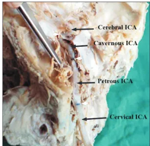
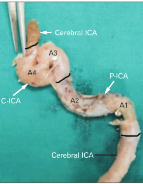
– Different segments of the artery (petrous, cavernous, and cerebral) were marked in situ after which the artery was removed from the cranium (Fig. 1).
The foetal ICAs were studied in situ after exposure of P-
ICA and C-ICA. No morphometric assessment was done in foetal ICAs.
Mophometric analysis
Measurement of lengths of different segments of the artery was done with the help of thread and vernier callipers. The length of petrous segment was marked at its entry into the ca- rotid canal at the base of the skull in petrous temporal bone, until its exit from foramen lacerum. The length of cavernous segment was taken from the exit point of the artery at fora- men lacerum to the point where the artery pierces the dura- mater medial to anterior clinoid process.
Measurement of angles in different segments of the artery was done with the help of a goniometer. To measure the an- gles, the arms of the goniometer were aligned along the long axis of the straight segments adjacent to the bends. The two bends of P-ICA were measured as angles A1 and A2. The C- ICA had two constant bends measured as angles A3 and A4.
Any extra bend present was named as A5.
Diameters of ICA were measured at the bends and at the middle of the straight segments between the bends with the help of thread and vernier calipers. Thus three diameters were measured in P-ICA namely D1, D2, and D3 at A1, A2 and the straight segment between A1 and A2, respectively. In C-ICA, the diameters measured were designated D4–D7 at straight segment between A2 and A3, at A3, at straight segment be-
Fig. 1. In-situ exposed internal carotid artery. The petrous temporal bone has been opened to expose the carotid canal and the petrous part of the internal carotid artery (ICA). The lateral wall of cavernous sinus has also been opened and retracted to expose the cavernous ICA. The white arrowheads point the demarcations of different parts of ICA.
tween A3 and A4, and at A4, respectively. The diameters were measured after opening the vessel and flattening the vessel wall in the region of interest. The circumference of the vessel was measured. Diameter were calculated from the circumfer- ence by using the formula: D=circumference/π.
Results
Fetal ICAThe five pairs of fetal ICA studied demonstrated the fol- lowing morphology. The cervical ICA coursed straight up- wards to enter the cranium. As it entered the cranium through the carotid canal, it bends and runs forwards, upwards, and medially with in petrous temporal bone until it reaches fora- men lacerum. Then, it bent and continued its course upwards, forwards, and medially until it reached the roof of cavernous sinus. The bends observed in the fetal ICA could not be mea- sured as the artery was very thin and delicate so the artery was studied in situ. A noteworthy fact, however, was that the C-ICA ran a relatively much straighter course as compared to the adult C-ICA. The bends observed were not acute bends and were rather gentle curves in order to change the direction of the vessel (Fig. 2).
Adult ICA P-ICA
The ICA entered the petrous temporal bone just anterior to the jugular foramen. It coursed through the carotid canal initially passing upwards and laterally for some distance, then it turned medially taking an acute bend to continue medi-
ally and forwards with in the carotid canal. It left the petrous temporal bone to enter foramen lacerum where it traveled through the cartilage to emerge into the floor of middle cra- nial fossa. While the artery ran through foramen lacerum, it took an obtuse bend (Fig. 1).
C-ICA
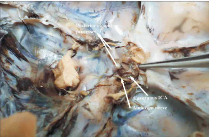
After emerging into middle cranial fossa, it immediately entered the cavernous sinus. Within the cavernous sinus, the artery ran in sagittal plane parallel to sella tursica and took a serpentine course until it pierced the dural roof of cavern- ous sinus and entered the subarachnoid space. The artery took two bends within the cavernous sinus. The first bend displayed considerable variation in its geometry ranging from gentle curve to sharp acute bend. The position of bend rises higher as the angle gets more and more acute. The second bend was an acute bend of around 45° that reversed the direc- tion of the artery backwards to constitute what is described in classical description as carotid siphon (Fig. 1). In four arteries (1 right and 2 left), an extra bend was observed in the C-ICA located between the constant bends.
Morphometric analysis
The morphometric analysis of the ICA which was done to gain an insight into the geometry of the vessel is as follows.
Tables 1–3 show descriptive statistics of various study param- eters.
The C-ICA was the longest and also the most variable part of the ICA, so much so that the range of length of this segment varied from 20 to 62 mm. Similar variability was ob- served in the angles of the artery.
Fig. 2. Fetal internal carotid artery (ICA) exposed in the cavernous sinus. Note the gentle curvature that the artery takes as it courses through the sinus.
Table 1. Lengths of P-ICA and C-ICA Length of P-ICA
(L1) (mm)
Length of C-ICA (L2) (mm)
Right Left Right Left
Valid 29 27 29 27
Mean 30.33a) 31.76 37.91 37.97
SD 6.650 6.46 8.86 8.90
Minimum 20.59 15.44 22.30 19.73
Maximum 51.93 41.18 62.72 55.29
P-ICA, petrous part of internal carotid artery; C-ICA, cavernous part of the internal carotid artery; L1, length of petrous segment; L2, length of cavernous segment; SD, standard deviation. a)Difference between right and left statistically not significant.
First bend A1
The first angle in P-ICA (A1) ranged from 31° to 110° with a mean of 83.19 and median of 85.5°.
Second bend A2
The second angle of P-ICA (A2) showed relatively con- stant character ranging from 90° to 120° and averaging about 102.75° and median value of 103°.
Third bend A3
This variability was also visualized in the bends of C-ICA.
The first bend of C-ICA or the third bend of ICA (A3) was found to be highly variable ranging from 21° to 134° with an average of around 83.98° and median value of 87°. In three cases (2 right, 1 left), this bend was in the form of a gentle curve and hence the angle could not be measured. This bend was classified into five types: type 1 to type 5.
Type 1 represented a gentle curve the vessel takes from fo- ramen lacerum towards anterior clinoid process (3 cases) (Fig.
3). Type 2 exhibited an obtuse angle >100° (15 cases) as seen in Fig. 4. Type 3 was the most commonly observed type (18
Table 2. Angles of P-ICA and C-ICA
First angle in P-ICAa) (A1) (°) Second angle in P-ICA (A2) (°) First angle in C-ICA (A3) (°) Second angle in C-ICA (A4) (°)
Right Left Right Left Right Left Right Left
Valid 29 27 29 27 27 26 29 27
Mean 84.06 82.25 102 103.55 78.62 89.53 40.96 46
SD 13.66 20.51 14.35 9.09 22.27 29.73 20.94 20.81
Minimum 59 31 68 89 45 21 11 14
Maximum 110 110 124 120 128 134 88 83
P-ICA, petrous part of internal carotid artery (ICA); C-ICA, cavernous part of the ICA; A1, first angle of petrous ICA; A2, second angle of petrous ICA; A3, first angle of cavernous ICA; A4, second angle of cavernous ICA; SD, standard deviation. a)Difference between right and left statistically not significant.
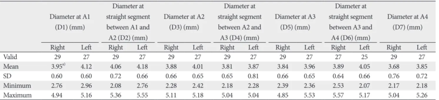
Table 3. Diameters of P-ICA and C-ICA Diameter at A1
(D1) (mm)
Diameter at straight segment between A1 and A2 (D2) (mm)
Diameter at A2 (D3) (mm)
Diameter at straight segment between A2 and A3 (D4) (mm)
Diameter at A3 (D5) (mm)
Diameter at straight segment between A3 and A4 (D6) (mm)
Diameter at A4 (D7) (mm)
Right Left Right Left Right Left Right Left Right Left Right Left Right Left
Valid 29 27 29 27 29 27 29 27 29 27 27 25 29 27
Mean 3.95a) 4.12 4.06 4.18 3.88 4.01 3.81 3.87 3.84 3.96 3.89 4.05 3.68 3.85
SD 0.60 0.60 0.72 0.66 0.66 0.65 0.65 0.81 0.66 0.65 0.64 0.66 0.76 0.72
Minimum 2.76 2.96 2.08 2.76 2.28 2.42 2.18 2.28 2.39 2.36 2.53 2.07 2.17 2.18
Maximum 4.94 5.16 5.36 5.55 5.11 5.18 5.04 5.04 4.85 5.53 5.57 5.17 5.04 5.26
P-ICA, petrous part of internal carotid artery (ICA); C-ICA, cavernous part of the ICA; A1, first angle of petrous ICA; A2, second angle of petrous ICA; A3, first angle of Cavernous ICA; A4, second angle of cavernous ICA; D1, diameter of ICA measured at first angle of its petrous segment; D2, diameter of ICA measured between first and second angle of petrous segment; D3, diameter of ICA measured at second angle of its petrous segment; D4, diameter of ICA measured between second angle of petrous segment first angle of cavernous segment; D5, diameter of ICA measured at first angle of its cavernous segment; D6, diameter of ICA measured between first and second angle of petrous segment; D7, diameter of ICA measured at second angle of its petrous segment. a)Difference between right and left statistically not significant.
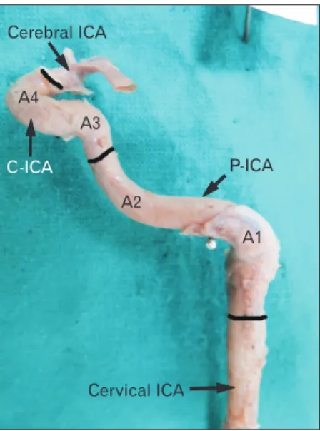
C-ICA
P-ICA A4
A3 A2 A1 Cerebral ICA
Cervical ICA
Fig. 3. Type 1 angulation. Note the gentle curve the cavernous ICA takes; specially the first bend of C-ICA (i.e., A3). The black bands demarcate different parts of ICA. ICA, internal carotid artery; P-ICA, petrous part of ICA; C-ICA; cavernous part of ICA; A1, first angle of petrous segment; A2, second angle of petrous segment; A3, first angle of cavernous segment; A4, second angle of cavernous segment.
cases) and was characterized by a near about right angle bend (80°–100°) as seen in Fig. 5. Type 4 bend was in the form of a sinuous curve taken by the artery (50°–80°) and was observed in 13 cases (Fig. 6). Type 5 exhibited a sharp bend almost like a hairpin bend in seven cases. The straight segment of the C- ICA between A2 and A3 was longer; the length of C-ICA was also longer (<50°).
Fourth bend A4
The second bend of C-ICA (A4) that constitutes carotid siphon was also very variable ranging from 11° to 88° with a mean of 43.43° and median of 41°.
Fifth bend A5
Angle A5, an extra bend was observed in three cases (1 right, 2 left) between A3 and A4. No obvious trend could be observed in the diameters measured at the bends and in the straight segments in between the bends.
Tables 4 and 5 shows correlation between length of P-ICA and C-ICA and their respective angles. It was observed that a negative and statistically highly significant correlation existed between length of petrous ICA and its first bend. However, no such correlation was observed in the cavernous part.
C-ICA A3
A2
A1 A4
Cerebral ICA
P-ICA
Cervical ICA
Fig. 4. Type 2 of angulation in A3. The A1 and A2 bends are right angle and obtuse respectively. Note that the A3 is slightly obtuse where as A4 is highly acute. The black bands demarcate different parts of ICA. ICA, internal carotid artery; P-ICA, petrous part of ICA;
C-ICA, cavernous part of ICA; A1, first angle of petrous segment; A2, second angle of petrous segment; A3, first angle of cavernous segment;
A4, second angle of cavernous segment.
C-ICA A3
A2 A1 A4
Cervical ICA
P-ICA Cerebral ICA
Fig. 5. Type 3 angulation in A3. Note a near right angle bend at A3.
Also notice that increase in acuty of A3 results in increase in vertical segment of C-ICA (i.e., between A3 and A4). The black bands demarcate different parts of ICA. ICA, internal carotid artery; P-ICA, petrous part of ICA; C-ICA, cavernous part of ICA; A1, first angle of petrous segment; A2, second angle of petrous segment; A3, first angle of cavernous segment; A4, second angle of cavernous segment.
C-ICA A3
A2
A1 A4
Cervical ICA P-ICA Cerebral ICA
Fig. 6. Type 4 angulation of A3. Note that the angle A3 is an acute bend and is almost at the level of A4. The black bands demarcate dif- fer ent parts of ICA. The black bands demarcate different parts of ICA.
ICA, internal carotid artery; P-ICA, petrous part of ICA; C-ICA, cavernous part of ICA; A1, first angle of petrous segment; A2, second angle of petrous seg ment; A3, first angle of cavernous segment; A4, second angle of cavernous segment.
Table 6 shows correlation between different angles at vari- ous bends. It was observed that generally the angulation at different bends were positively correlated to each other. How- ever, statistically highly significant positive correlation was observed between the A4 (carotid siphon) of cavernous seg- ment and the remaining three bends.
Atherosclerotic plaques were observed in seven ICAs (4 right and 3 left of which one was bilateral). These plaques were located (1) along the anterior aspect of vessel wall at the A4 bend in four cases (2 right, 2 left); (2) at A3 and the straight segment between A3 and A4 in two cases (1 right, 1 left). (3) The A3 in all these cases was less than 90° and A4 ranged between 14° and 83° at A1 and just distal to it in P- ICA (A1=85°).
Discussion
The bends of the ICA have been widely described in ana- tomical and standard texts as angles or knees [1, 2, 10, 11].
However very few studies have quantified these bends and have performed three dimensional reconstruction. McVay [10] have stated that in its passage through the petrous tem- poral bone the artery takes a series of sharp bends in several directions finally entering the cranial cavity.
The angle A1, i.e., first intrapetrous bend was an acute bend measuring approximately 82°. A wide variation was observed in this angle ranging from it being very acute to obtuse. This may be accounted for, as the lateral end of ca- rotid canal, which houses this bend, is roomy and provides space for change in direction of the vessel. Keshelava et al.
[12] reported this angle to be an obtuse angle measuring 105°
studied in eight cadaveric specimens [3]. The angle A2, i.e., second bend in petrous ICA has not received much attention.
This angle was less variable probably due to passage of artery through the cartilage of foramen lacerum.
The cavernous portion of the ICA has been also described as parasellar ICA [9, 13]. The angle A3, i.e., first bend in C- ICA was found to be very variable ranging from 21° to 134°
with an average of around 90°. The position of this bend was also found to be variable. Obtuse bends lying at a lower level
Table 4. Correlation between the lengths and angles of P-ICA
A1 A2
Length of petrous segment (L1) –0.352* 0.047 Pearson correlation Sig. (2-tailed) 0.008 0.731 P-ICA, petrous part of internal carotid artery (ICA); A1, first angle of petrous ICA; A2, second angle of petrous ICA. *Correlation is significant at the 0.01 level (2-tailed).
Table 5. Correlation between the lengths and angles of C-ICA
A3 A4
Length of cavernous segment (L2) –0.085 0.005 Pearson correlation Sig. (2-tailed) 0.544 0.970 C-ICA, cavernous part of the internal carotid artery (ICA); A3, first angle of cavernous ICA; A4, second angle of cavernous ICA.
Table 6. Correlation between different angles of P-ICA and C-ICA
A1 A2 A3 A4
A1 Pearson correlation 1 0.317* 0.207 0.480**
Sig. (2-tailed) 0.017 0.136 0.000
A2 Pearson correlation 0.317* 1 0.332* 0.330*
Sig. (2-tailed) 0.017 0.015 0.014
A3 Pearson correlation 0.207 0.332* 1 0.496**
Sig. (2-tailed) 0.136 0.015 0.000
A4 Pearson correlation 0.480** 0.330* 0.496** 1
Sig. (2-tailed) 0.000 0.014 0.000
P-ICA, petrous part of internal carotid artery (ICA); C-ICA, cavernous part of the ICA; A1, first angle of petrous ICA; A2, second angle of petrous ICA; A3, first angle of cavernous ICA; A4, second angle of cavernous ICA. *Correlation is significant at the 0.05 level (2-tailed). **Correlation is significant at the 0.01 level (2-tailed).
C-ICA
A3
A2 A1
A4
Cerebral ICA
P-ICA Cerebral ICA
Fig. 7. Type 5 angulation of A3. Note an acute hairpin bend of A3 which is at a higher level than that of A4 angle. The black bands demar- cate different parts of ICA. ICA, internal carotid artery; P-ICA, pet- rous part of ICA; C-ICA, cavernous part of ICA; A1, first angle of petrous segment; A2, second angle of petrous segment; A3, first angle of cavernous segment; A4, second angle of cavernous segment.
than acute bends which were at a higher level and almost reached the posterior clinoid process. Present study has clas- sified this angle with increasing acuity into five types. On one extreme (type 1) this angle was just a gentle curve resembling the fetal ICA and on another extreme (type 5) the vessel was highly kinked. Jittapiromsak et al. [13] have also described A3 as ICA curve angle. According to them in one-third of cases studied the angle was above the horizontal segment and classified it as redundant ICA [13]. Such highly placed acute bends of C-ICA abut the posterior clinoid process and poste- rior part of pituitary and are known to cause compression of pituitary and erosion of dorsum sellae [14].
The distal bend also described as carotid siphon has been often studied. Isolan et al. in 2005 [3] reported the angulation at carotid siphon i.e. A4 to be approximately 90° in 24 speci- mens he studied [14]. Bogunovic et al. in 2011 [15] in a retro- spective study correlating carotid siphon angle with presence of aneurysms concluded that narrow carotid siphon may alter haemodynamic stress and consequently influence the forma- tion of both posterior communicating and anterior commu- nicating arteries in susceptible individuals. In a very recent study, Zhang et al. [16] correlated the stenosis of ICA while giving a novel classification for characterization of carotid si- phon as ‘U’ shaped ‘V’ shaped ‘C’ shaped and ‘S’ shaped. The present study has also documented wide variation in A4. Ca- rotid siphon is a known, measurable radiological entity. The strong positive, statistically significant correlation of carotid siphon (A4) with other bends of the ICA, as observed in the present study, implies that a narrow carotid siphon is an indi- cation of more tortuous ICA.
Lengths
Kim and Kang in 2007 [17] intraoperatively measured the length of supraclinoid ICA in patients with anterior or middle cerebral artery aneurysms. They concluded that a relatively shorter length of supraclinoid ICA may be a novel risk factor for the development of ICA—posterior communicating aneu- rysms with higher hemodynamic stress. The statistical analy- sis of the present study indicates that the length of the ICA in petrous and cavernous part is negatively correlated to the bends. A longer length results in increasing acuity of the bend [18]. Thus a longer more tortuous artery may be a response to cope with increasing hemodynamic stress.
Not many studies have been conducted on measurements of diameters of different segments of intracranial ICA. Avail- able studies document diameters slightly higher than the
present study. This difference may be attributed to the inner diameter measured in the present study as compared to outer diameters measured by others [19, 20].
Patho-anatomy of vascular lesions
The present study has documented that the geometric complexity of C-ICA ranges from a gentle curve to an acute posterior bend and a narrow carotid siphon. The posterior bend of ICA is very variable and has been classified it into five types by the authors. It is noteworthy that type I the foetal type is relatively straighter ICA having a wider carotid siphon (A4); and type V is highly tortuous, longer and has a narrow carotid siphon.
The tortuosity of intracranial ICA and its possible impli- cations on hemodynamics and condition of vessel wall have generated interest in the recent past. Meng et al. in 2008 [7]
provided three-dimensional description and mathematical characterization of the C-ICA in human infants and observed that the incidence of pre-atherosclerotic lesions is linked with the complexity of the C-ICA. They argued that while the fetal C-ICA is relatively straight, the growth dynamics of vessel length vis a vis skull bones create a spatial constraint resulting in transformation of C-ICA during postnatal period and also in childhood and adolescence. However, they also acknowledge that hemodynamic forces may also trigger vas- cular remodelling and postnatal P-ICA transformation. The findings of the present study have created a reference data of unsuspected adult population and has potential implications for studying cause/effect relationship of vessel geometry and hemodynamic factors.
According to Jittapiromsak et al. [13] the curves and seg- ments of cavernous ICA is a consequence of how middle cra- nial fossa develops. The segments that involve most vascular pathologies are the posterior bend and horizontal segment where intracranial branching occurs. These segments also tend to be involved in intracranial traumatic cases [13].
Fetal ICA
Our observations on fetal ICA indicate that the artery runs a relatively straighter course in fetal life taking gentle curves while it changes its course in different planes. We could not find any study describing the morphology of fetal ICA in lit- erature. In an excellent analysis by Weninger et al. in 1999 [9], they showed association of intimal hyperplasia in infant para- sellar carotid artery with occurrence of sudden infant death syndrome (SIDS). In another analysis of infant parasellar
ICAs, Meng et al. in 2008 [7] described four constant bends in infant ICA.
Both these studies infer that infants with persisting straight- er course of ICA do not develop intimal cushions (precursors of atherosclerosis) that can extensively occlude the lumen of blood vessel during the first year of life and hence should be less prone to develop SIDS. They suggest that the shape trans- formation process of parasellar ICA is a vulnerable phase of vessel wall development in which intimal hyperplasia can eas- ily occur.
When compared with adults the type 1 which resembles the fetal ICA was observed only in three cases. The maxi- mum cases observed were of type 3 (signifying a moderately tortuous artery). This indicates that the ICA mostly does not retain its simple curves and is modelled to become more tortuous as an individual grows. Further age related studies are required to prove this fact. According to Weninger et al.’s study [9], adults who retain a straighter course of parasellar ICA throughout their lives will have a lower predisposition to develop atherosclerotic plaques in these locations and conse- quently should have reduced risk of stroke.
References
1. Standering S. Gray’s anatomy: the anatomical basis of clinical practice. 39th ed. London: Churchill Livingstone; 2005. p.295-8.
2. Sinnatamby CS. Lasts anatomy: regional and applied. 10th ed.
London: Elsevier-Churchill Livingstone; 1999. p.438-65.
3. Isolan G, de Oliveira E, Mattos JP. Microsurgical anatomy of the arterial compartment of the cavernous sinus: analysis of 24 cav- ernous sinus. Arq Neuropsiquiatr 2005;63:259-64.
4. Liu JK, Fukushima T, Sameshima T, Al-Mefty O, Couldwell WT.
Increasing exposure of the petrous internal carotid artery for re- vascularization using the transzygomatic extended middle fossa approach: a cadaveric morphometric study. Neurosurgery 2006;
59(4 Suppl 2):ONS309-18.
5. Osawa S, Rhoton AL Jr, Tanriover N, Shimizu S, Fujii K. Micro- surgical anatomy and surgical exposure of the petrous segment of the internal carotid artery. Neurosurgery 2008;63(4 Suppl 2):210-38.
6. Paullus WS, Pait TG, Rhoton AI Jr. Microsurgical exposure of the petrous portion of the carotid artery. J Neurosurg 1977;47:
713-26.
7. Meng S, Costa Lda F, Geyer SH, Viana MP, Reiter C, Müller GB, Weninger WJ. Three-dimensional description and mathematical characterization of the parasellar internal carotid artery in hu- man infants. J Anat 2008;212:636-44.
8. Meng S, Geyer SH, Costa Lda F, Viana MP, Weninger WJ. Ob- jective characterization of the course of the parasellar internal carotid artery using mathematical tools. Surg Radiol Anat 2008;
30:519-26.
9. Weninger WJ, Müller GB, Reiter C, Meng S, Rabl SU. Intimal hyperplasia of the infant parasellar carotid artery: a potential developmental factor in atherosclerosis and SIDS. Circ Res 1999;
85:970-5.
10. McVay CB. Surgical anatomy. 6th ed. Philadelphia, PA: W.B.
Saunders; 1984. p.34, 35, 90, 91.
11. Moore KL, Dally AF. Clinically oriented anatomy. 5th ed. Balti- more, MD: Lippincott Williams & Wilkins; 2006. p.927-9.
12. Keshelava G, Mikadze I, Abzianidze G, Kikalishvili L, Kakabadze Z. Surgical anatomy of petrous part of the internal carotid artery.
Neuroanatomy 2000;8:46-8.
13. Jittapiromsak P, Sabuncuoglu H, Deshmukh P, McDougall CG, Spetzler RF, Preul MC. Anatomical relationships of intracavern- ous internal carotid artery to intracavernous neural structures.
Skull Base 2010;20:327-36.
14. McLachlan MS, Williams ED, Doyle FH. Applied anatomy of the pituitary gland and fossa: a radiological and histological study based on 50 necropsies. Br J Radiol 1968;41:782-8.
15. Bogunović H, Pozo JM, Cárdenes R, Frangi AF. Anatomical labeling of the anterior circulation of the Circle of Willis using maximum a posteriori classification. Med Image Comput Com- put Assist Interv 2011;14(Pt 3):330-7.
16. Zhang C, Pu F, Li S, Xie S, Fan Y, Li D. Geometric classification of the carotid siphon: association between geometry and steno- ses. Surg Radiol Anat 2013;35:385-94.
17. Kim DW, Kang SD. Association between internal carotid artery morphometry and posterior communicating artery aneurysm.
Yonsei Med J 2007;48:634-8.
18. Sakamoto S, Ohba S, Shibukawa M, Kiura Y, Okazaki T, Arita K, Kurisu K. Characteristics of aneurysms of the internal carotid artery bifurcation. Acta Neurochir (Wien) 2006;148:139-43.
19. Arat YO, Arat A, Aydin K. Angiographic morphometry of inter- nal carotid atery circulation in Turkish children. Turk Neurosurg 2015;25:608-16.
20. Takegoshi H, Kikuchi S. An anatomic study of the horizontal petrous internal carotid artery: sex and age differences. Auris Nasus Larynx 2007;34:297-301.