Vol. 25, No. 4, pp. 468-475, June 30, 2019, ISSN 1229-3431(Print) / ISSN 2287-3341(Online) https://doi.org/10.7837/kosomes.2019.25.4.468
1
1. Introduction
Hazards are the natural gas characteristic with the inherent ability. Flammability, toxicity, corrosivity, stored chemical or
* First Author : [email protected]
†Corresponding Author : [email protected], 061-240-7239
mechanical energy are hazards associated with various industry especially in shipping. In state of the art, a growth in the demand for natural gas has led to an increased number of gas tankers.
Thus, safety issues on the ships are extremely urgent, especially the safety of LPG tanks. A flame arrester is a device which allows gas to pass through it but stops a flame in order to prevent a large fire or explosion. On the ship, the flame arrester normally is
A Study on the Element Technologies in Flame Arrester of End Line
Minh-Ngoc Pham
*․Min-Seon Choi
**․Bu-Gi Kim
***†* Graduate School of Mokpo National Maritime University, Mokpo 58628, Korea
** Division of Marine Engineering System, Mokpo National Maritime University, Mokpo 58628, Korea
*** Division of Marine Mechatronics, Mokpo National Maritime University, Mokpo 58628, Korea
선박의 엔드라인 폭연방지기의 요소기술에 관한 연구
팜민억
*․최민선
**․김부기
***†* 목포해양대학교 대학원, ** 목포해양대학교 기관시스템공학부, *** 목포해양대학교 해양메카트로닉스학부
Abstract :An end-line flame arrester allows free venting in combination with flame protection for vertical vent applications. End-line flame arresters are employed in various fields, especially in shipping. In flame arresters, springs are essential parts because the spring load and the spring's elasticity determine the hood opening moment. In addition, the spring has to work under a high-temperature condition because of the burning gas flame. Therefore, it is necessary to analyze the mechanical load and elasticity of the spring when the flame starts to appear. Based on simulations of the working process of a specific end-line flame arrester, a thermal and structural analysis of the spring is performed. A three-dimensional model of a burned spring is built using computational fluid dynamics (CFD) simulation. Results of the CFD analysis are input into a finite element method simulation to analyze the spring structure. The research team focused on three cases of spring loads: 43, 93, and 56 kg, correspondingly, at 150 mm of spring deflection. Consequently, the spring load was reduced by 10 kg after 5 min under a 1,000 ºC heat condition. The simulation results can be used to predict and estimate the spring’s load and elasticity at the burning time variation. Moreover, the obtained outcome can provide the industry with references to optimize the design of the spring as well as that of the flame arrester.
Key Words : Flame Arrester, Shipping, CFD, FEM, Spring
요 약 : 엔드라인 폭연방지기는 수직 환기장치에 폭연방지와 함께 대기방출을 하도록 한다. 엔드라인 폭연방지장치는 선박과 같은 산 업현장의 다양한 분야에 적용된다. 폭연방지기에서 스프링은 스프링 부하와 스프링의 탄성이 후드 개방 모멘트를 결정하므로 필수 부품 이다. 더욱이, 장치 내 스프링은 고온의 상태에서도 작동해야 한다. 따라서, 폭연이 나타나기 시작할 때 스프링의 기계적 하중과 탄성을 분석할 필요가 있다. 이 연구에서는 엔드라인 폭연방지기의 작동 프로세스의 시뮬레이션을 기반으로 열 및 구조해석을 수행하으며, 스프 링의 3차원 모델은 CFD 시뮬레이션을 이용하였다. CFD 해석은 FEM 시뮬레이션 값을 입력하여 스프링 구조를 분석한다. 본 연구에서는 스프링 부하의 43 kg, 93 kg 및 56 kg 세 가지 경우 즉, 150 mm 스프링 디플렉션에 부합하도록 집중적으로 관찰하였다. 결과적으로, 1,000℃
가열조건 하에서 5분 후에 스프링 부하가 10 kg 감소했다. 시뮬레이션 결과는 연소 시간 변화에 따라 스프링의 부하와 탄성을 예측하고 추정할 수 있었다. 또한, 연구의 결과는 폭연방지기의 제조자들에게 역화방지장치뿐만 아니라 스프링의 설계를 최적화하기 위한 참고 자 료로 활용할 수 있다.
핵심용어 : 폭연방지기, 선박, 전산유체역학, 유한요소해석, 스프링
installed on gases line or LPG tanks. The flame arresters selection and investigation should be carefully performed to ensure that the device reliably operates in the event of a malfunction. In this research, the authors focuses on end-line flame arresters which arranged on the top of LPG tanks as ventilation and light-back preventing equipments. The flame arrester's spring plays an important role in determining the hood opening time which ensure a stable temperature.
In previous studies, the springs calculation in thermal conditions are not mentioned. Other researchers have been carried out some spring structural analysis in order to develop spring design (Pavani et al., 2014; Weggel et al., 2007). However, there were research limitations in spring dynamic response under high temperature conditions.
Therefore, the main objective of the presented work is performance in the spring dynamic response of specific medium-size flame arresters model, so as to predict and evaluate the springs mechanical elasticity and stresses. Finally, the simulation results can be used to estimate the maker’s springs design.
2. Numerical Methodology
2.1 Computational model
Fluid Structure Interaction (FSI) model which combine Computational Fluid Dynamic (CFD) model and Finite Element Method (FEM) are applied to predict spring load and spring elasticity under high temperature working conditions. The author performs two separate simulations which are CFD simulation and FEM simulations. The CFD model is used to indicate spring thermal conditions under the influence of a 1,000℃ natural gas flame. Then, spring thermal conditions are used as a boundary condition in the FEM model to investigate spring elasticity and load.
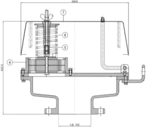
Firstly, the flame arrester 3D model is designed in Solidworks, based on the flame arrester diagram which is shown in the Fig. 1 and Table 1 illustrated the main parts. The flame arrester model is imported in ANSYS. In ANSYS, the finite element model of the flame arrester is built. The flame arrester geometry is divided. In order to save simulation time while still achieving the accuracy requirements, the numerical model should be reduced parts that have undramatical effect on simulation results such as hinge, hinge post, guide post etc.
As described in Fig. 1, in the normal state, the flame arrester operates as a gas tankers ventilator. However, in case of occurring
flame, the flame arrester will have a function as a safety device.
Due to the natural gas have been burning, a flame arises in the flame arrester. If the flame arrester is absent, the flame will flow back into the gas tank cause of an explosion. However, due to the special design, the flame going through the element assembly④, the flame temperature decreases and prevent the combustion takes place in the tank. Though, after a amount of certain time, the hood⑦ needs to be opened so that the fire at the flame arrester is steadily maintained, against the fire in the tank. This process is highly dependent on fuse⑤ and spring⑥. If the spring load is insufficiently large, the hood could not opened. In contrast, if the spring load is extreme large, thereby resulting in the a damage the hood or premature hood opening.
The CFD and FEM model is meshed independently. The numerical model adopted hexa and tetra mesh style which consists of 2.1 million nodes for CFD model and 1.1 million nodes for FEM model (Fig. 2). The mesh quality values are in acceptable range for both models.
Fig. 1. The flame arrester diagram.
Fig. 2. Meshing Geometry of CFD annd FEM models.
2.2 Boundary conditions
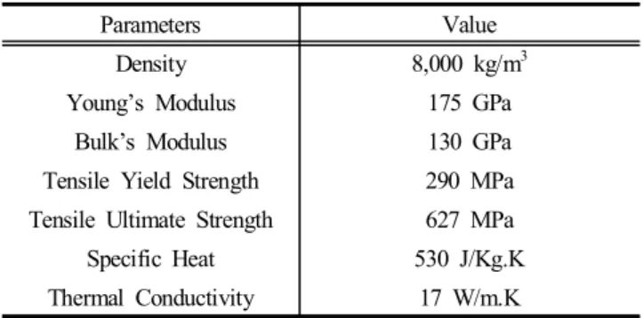
In order to ensure simulations and evaluations of the Spring in the Flame Arrester close to the actual conditions, the spring materials need to be setup in CFD and FEM models in commercial code program. The Table 1 details the basic spring material properties which affect the spring load and elasticity in ambient conditions (at 25℃). The case setup for the spring is presented in Table 2.
Springs selection based on the comparison between the results of the experiment and simulation. Initially, the selected spring load value was 43 kg, this value did not meet the requirement for the hood to open at the right moment. Then, the spring load should be increased to 93 kg by changing the wire diameter, but this led to the hood opening fast and closing back. Finally, the 56 kg selected spring load is in accordance with the manufacturer's requirements.
Parameters Value
Density 8,000 kg/m3
Young’s Modulus 175 GPa
Bulk’s Modulus 130 GPa
Tensile Yield Strength 290 MPa
Tensile Ultimate Strength 627 MPa
Specific Heat 530 J/Kg.K
Thermal Conductivity 17 W/m.K
Table 1. Stainless Steel STS 316 mechanical Properties
Case 1 2 3
Spring Material STS 316 STS 316 STS 316
Spring Inside Diameter(mm) 86 86 86
Wire Diameter(mm) 7 8 7
Number of Active Coil 9 7 7
Free Length(mm) 300 300 300
Spring Deflection(mm) 150 150 150
Table 2. Spring Models Cases
Because the STS 316 is stainless steel, tensile yield strength is less than half of the ultimate tensile strength. Specific heat at an ambient temperature is 530 J/kg.K but this value decrease depending on the material temperature. Thermal conductivity is insignificant fluctuations so this value is kept constant in setting the boundary conditions.
Base on the database of Structural Steel, STS 301, STS 316 on the www.matweb.com website of material property data, Fig. 3 and Fig. 4 illustrated the Density and Young’s Modulus depend on temperature. While Young modulus significantly influences the load and springs elasticity, density has fewer effect on these parameters.
Because of working in high temperature condition, the mechanical properties of STS 316 material is changed due to the temperature of the material itself. Although the Young’s modulus of structural steel is higher than stainless steel, this value can be dramatically reduce in high temperature as shown in Fig. 3. Stainless steel is chosen to create a spring in flame arrester. In comparison between stainless steel 304 and stainless steel 316, the stiffness of STS 316 is more advantage (Lingaiah and Narayana, 2006).
0 100 200 300 400 500 600 700 800 900 1000
6900 7000 7100 7200 7300 7400 7500 7600 7700 7800 7900 8000 8100
Density (kg/m3)
Temperature (oC)
STS 301 STS 316 Structural steel
Fig. 3. Density and Temperature Graph.
In the FEM model, it is necessary to figure out the Tangent Modulus. These equations is according to LS-DYNA support which expressed the relationship between True Strain and True Stress.
They can be calculated by under formulas:
- True Strain = ln(1 + Engineering Strain)
- True Stress = Engineering Stress*(1 + Engineering Strain) - Yield Strain = Yield Strength/Modulus of elasticity - Tangent Modulus = ((True Ultimate Stress-Yield Stress) / (Strain at true Ultimate - (Yield Strain + 0.02))
0 100 200 300 400 500 600 700 800 900 20
40 60 80 100 120 140 160 180 200 220 240
Young's Modulus (GPa)
Temperature (oC)
STS 301 STS 316 Structural steel
Fig. 4. Young’s Modulus and Temperature Graph.
While engineering stress-strain can be widely used in small-strain analyses, true stress-strain must be used in large deformation. In solid mechanics, the tangent modulus is the slope of the stress-strain curve at any specified stress or strain. Below the proportional limit, the tangent modulus is equivalent to Young's modulus. In contrast, above the proportional limit, the tangent modulus varies with strain and is accurately found from test data.
The Ramberg-Osgood equation relates Young's modulus to the tangent modulus, this is a method to obtaining the tangent modulus (Kapadia and Sonami, 2016). The tangent modulus is input in Engineering Data in Ansys program, listed in Table 3.
Temperature (℃)
Yield Strength (MPa)
Tangent Modulus (MPa)
204 241 1539.3
316 214 1570
427 190 1593
538 165 1544
649 145 1284.3
760 124 701.48
Table 3. Tangent Modulus Properties
The Tangent Modulus is separated at each temperature 204℃, 316℃. etc. The other Tangent Modulus automatically find out by the interpolation in Commercial Program. These values are based on the stainless steel STS 316 experiment at different temperature
levels. The other material parameters are depend on the temperature, but the spring plasticity state investigation is unconsidered. Parameters related to the material plasticity are not mentioned.
Next to tangent modulus, the shear modulus is play an important role in spring load influence. However, this parameter is calculated by using young’s modulus in FEM commercial code program.
Boundary conditions Value
Burning Flame Temperature(℃) 1,000
Burning Flame Velocity (m/s) 1
Ambient Temperature(℃) 25℃
Ambient Pressure (atm) 1 atm
Table 4. The operating conditions of the Springs
Based on the maker's experiment, the flame temperature is from 800℃ to 1,000℃, the velocity of combustion air flow is 1 m/s, so the temperature of the flame will be set at 1,000℃ in the simulation as shown in the Table 4.
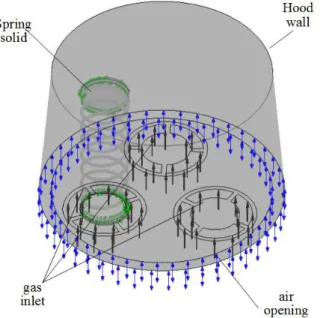
In the CFD model using CFX software, there are two domains are illustrated on Fig. 5. Because heat transfer need to be measured, the fluid and solid domain are setup independently (Syambabu, 2015; Pinjarla and Lakshmama 2012). The Fluid domain is used to compute burning flame as well as the environment around spring. Solid domain is used to simulate spring material. The boundary outside the spring is fluid and accompanied by temperature, velocity and flow conditions. Based on the flame arrester initial design, the flame will appear in the green area at an initial 1,000℃ temperature.
Parameters Value
Ratio of Specific Heat 1.3224
Specific Heat (Cp) (J/g.K) 1.177 Thermal Conductivity (cal/cm/sec.K) 1.87
Pressure (atm) 1
Temperature (℃) 1,000
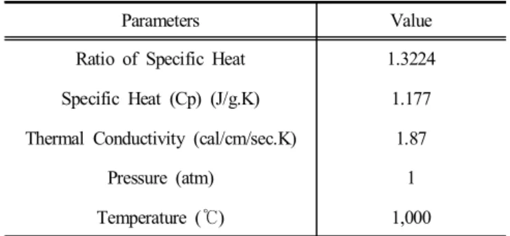
Table 5. The natural gas flame properties
Fig. 5. Computational domain.
The blue arrows indicate the burning gas flame flowing out flame arrester, where the boundary conditions are chosen as the opening pressure because it is impossible to predict the velocity, pressure and direction of the flame. The simulation model uses two domains so it is necessary to establish the interfaces between them.
In CFD model, these interfaces are set by default as conservative interface flux. The selected hood wall boundary has a certain 1.5 mm thickness and uses heat transfer coefficients corresponding to STS 316 as the design.
Because of the different between air and natural gas flame heat transfer coefficient, the flame heat transfer parameters need to be established according to previous studies. The Table 5 shows the natural gas flame properties in 1,000℃.
The burning gas parameter choice is based on the experiments when natural gas is burned under different pressure conditions and the ratio of natural gas and air.
In all cases, the boundary conditions is similar. Conservation laws such as mass, momentum, and volume conservations are used as basic equation for numerical model. Besides, the thermodynamic laws also applied in heat transfer equations.
The Table 6 illustrate the spring's case studies. The spring material is STS 316. The inner diameter is similar in all cases.
The wire diameter and number of active coils chosen to modified.
These changes will be effect on the spring elasticity.
Case 1 2 3
Type of spring KSED-6 KSED-6 KSED-6
Spring materials STS
316
STS 316
STS 316
Spring inner diameter (mm) 86 86 86
Wire Diameter (mm) 7 8 7
Number of active coils 9 7 7
Free Length (mm) 300 300 300
Spring Deflection (mm) 150 150 150
Simulation spring elasticity
(N/mm) 2.972 7.135 3.866
Calculation spring elasticity
(N/mm) 2.868 6.498 3.688
Difference 3.5 % 8.9 % 4.65 %
Table 6. The spring elasticity comparisons
Fig. 6. Spring deflection and fixed support.
The CFX software solve the spring temperature which are imported to Structural Analysis as input data. It is common to use the finite element method which contains the equations for static analysis (Analysis Guide, 2016). In order to simulate the spring compressed under thermal conditions, the spring deflection and fix supports is inserted in FEM model as Fig. 6.
The spring deflection is set at 150 mm and the time steps in model is divided into 100 small steps in purpose of ensuring load conservations. Moreover, the contact status between spring face is frictionless and the stiffness of these faces is 1. The higher stiffness is set, the more accurate results achieve. However, the conservation is unable to reach if stiffness is unreasonable. Finally, Spring load, Spring elasticity and equivalents stresses is obtained.
3. Results and Discussions
3.1 Springs Analysis without Thermal conditions
Before calculating and considering springs in thermal working conditions, the spring elasticity and load are measured in terms of ambient temperature. This calculation allows the determination of errors between simulation and calculation.
Spring elasticity can be approximated by the following formula:
D
d
(1)
k is spring elasticity, G is shear modulus, d is wire diameter, D is outer spring diameter. According to this formula, small changes in the wire diameter will lead to noticeable changes in spring elasticity.
The largest difference between the calculated result and the simulation result is 8.9 % in case 2. Nevertheless, this value is acceptable because in case 2, the load of the spring is relatively large up to 93 kg. On the other hand, the simulated spring elasticity is always higher than the computation. Therefore it is important for considering simulation results to ensure that the results is as close to practical as possible.
3.2 Thermal conditions of Spring
After solving in Thermal Analysis, maximum and minimum temperature of the spring in all cases are described in Fig. 7.
Temperature values are calculated and recorded at certain times.
0 30 60 90 120 150 180 210 240 270 300 330
0 0 50 100 100 150 200 200 250 300 300 350 400 400 450 500 500 550 600 600 650
Temperature (oC)
Burning time (Second) Mi n temperature in case 1 Max temperature in case 1 Mi n temperature in case 2 Max temperature in case 2 Mi n temperature in case 3 Max temperature in case 3
Fig. 7. Min and Max Temperature on the Spring.
According to Fig. 7, minimum and maximum spring temperatures are little different in threes cases after 5 minutes in gas burning flame. After 5 minutes under natural flame working condition, in all case the maximum springs temperature are higher than 500℃, but the spring temperature in case 1 is slightly higher the other cases. The spring temperature increases quite rapidly in the first 30s but the spring temperature augmentation decreases because the springs temperature different between bottom and top is about 975℃ at the beginning.
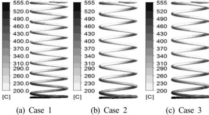
(a) Case 1 (b) Case 2 (c) Case 3 Fig. 8. Temperature Contour of Spring after 5 minutes.
Though of working at high temperatures is 1,000℃ during 5 minutes, the spring temperature is not exceed 600℃. The stainless steel thermal conductivity is one quarter compared to other types of steel such as structure steel is 67 W/m.K. Due to the structural shape, high temperature airflow will tend to swirl vertically near the outlet boundary. In order to saving computer resources and simulation time, the domain construction surrounding the flame arrester is unconsidered. Instead, the outlet boundary is set to opening with a temperature value of 300℃ based on the experimental results.
It is seen that in Fig. 8 the spring temperature unevenly distributed. High temperatures are concentrated in the spring lower part, because the flame transfer heat from the bottom to the top while the fire rate is only 1 m/s. The lowest temperature is found in the body center of the spring, which is due to the spring pad influence.
3.3 Spring Load and Spring Elasticity
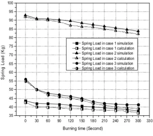
Based on the thermal conditions, Spring Load and Spring Elasticity are calculated in structural analysis. The Spring load in three cases are presented in Fig. 9
As the Fig. 9 illustrated, in all three cases, the spring load drop rapidly during the first 30 seconds firing and decrease gradually after 5 minutes in high temperature. For the first 30 seconds, the
spring temperature considerably decreases, leading to a rapid spring's hardness deterioration and a rapid decrease in the Young’s modulus coefficient. Thus, the springs load change dramatically in the beginning fire period. Springs load after firing 5 minutes reduce from 7 to 12 kg. In particular, in case 3, in the first 30 seconds since the fire appearance, the load drops to 6 kg while it is only 2 kg for cases 1 and 2. The phenomenon reason is that the spring in case 2 has wire diameter and number of active coil is the smallest.
0 30 60 90 120 150 180 210 240 270 300 330 35
40 45 50 55 60 65 70 75 80 85 90 95 100
Spring Load (Kg)
Burning time (Second)
Spring Load in case 1 simulation Spring Load in case 1 calculation Spring Load in case 2 simulation Spring Load in case 2 calculation Spring Load in case 3 simulation Spring Load in case 3 calculation
Fig. 9. Spring Load in 3 cases.
Obviously, spring elasticity is slightly reduced in the first 30 seconds as shown in the Fig. 10, but there are significant differences in this value in all cases. Although the spring load in the second case is almost twice that of the first and the third, the spring's elasticity in third case is reduced more slowly compared to the others (PTB, 2010).
0 30 60 90 120 150 180 210 240 270 300 330 2.0
2.5 3.0 3.5 4.0 4.5 5.0 5.5 6.0 6.5
Spring Elasticity (N/mm)
Burning time (Second)
Spring Elasticity in case 1 Spring Elasticity in case 2 Spring Elasticity in case 3
Fig. 10. Spring Elasticity in 3 cases.
3.4 Equivalent stresses on Springs
The spring equivalent stresses are shown in Fig. 11. The equivalent stress calculation allows the assessment of the material stiffness in different cases. This value not only depends on the material nature but also on the working conditions (Chiu et al., 2007).
(a) Case 1 (b) Case 2 (c) Case 3 Fig. 11. Equivalent stress in 3 cases.
The equivalent stress in case 1, case 2 and case 3 are 859 MPa, 1,074 MPa and 871 MPa respectively. the equivalent stresses are evenly distributed at middle of springs and the minimum stresses are find out at lowest and highest positions. Because of the different design, the stress on the springs in the case of difference.
From the graphs it is observed that for all types of springs, the spring material stiffness is more effective corresponding stresses will increase.
4. Conclusions
This paper introduce part of author’s work on long term study about the flame arresters structural analysis. To summarize the work presented above, conclusions are made below:
1) The spring temperature unevenly distributed. High temperatures are concentrated in the spring lower part. In addition, the lowest temperature is found in the body center of the spring, which is due to the spring pad influence.
2) In all three cases, because of spring pad, the spring load decrease rapidly during the first firing 30 seconds and then gradually decrease after 5 minutes in high temperature.
3) The equivalent stress in case 1, case 2 and case 3 are 859 MPa, 1074 MPa and 871 MPa respectively. The equivalent stresses are evenly distributed at middle of springs and the minimum stresses are found out at lowest and highest positions. The spring material stiffness increases corresponding stresses will increase.
Acknowledgements
This study was financially supported by Mokpo National Maritime University, 2017.
References
[1] Analysis Guide(2016), ANSYS, Inc. ANSYS Mechanical ADPL Structural Analysis Guide.
[2] Chiu, C. H., C. L. Hwan, H. S. Tsai and W. P. Lee(2007), An experimental investigation into the mechanical behaviors of helical composite springs, Compos. Struct., Vol. 77, Issue 3, pp. 331-340.
[3] Kapadia, D., P. H. Desai and A. Sonami(2016), Design and Analysis of composite leaf spring for light weight vehicle, International Journal of engineering sciences and research technology, Vol. 3, Issue 6, pp. 666-672.
[4] Lingaiah, K., and B. R. Narayana Iyengar(2006), Machine Design Data Handbook, Suma publishers.
[5] Pavani, P. N. L., B. K. Prafulla, R. Pola Rao and S.
Srikiran(2014), Design, Modeling and Structural Analysis of Wave Springs, 3rd International Conference on Materials Processing and Characterisation (ICMPC 2014), Procedia Materials Science, Vol. 6, pp. 988-995.
[6] Pinjarla, Poornamohan and T. Lakshmama Kishore(2012), Design and analysis of a shock absorber, International Journal of Research in Engineering and Technology, Vol. 1, Issue 4, pp. 578-592.
[7] PTB(2010), Physikalich Technische Bundesanstalt, EC type- examination certificates of static flame arresters with crimped ribbon flame arrester elements.
[8] Syambabu Nutalapati(2015), Structural analysis of shock absorber by using ANSYS, International Journal of Engineering Research-Online, Vol. 3, Issue 6, pp. 588-608.
[9] Weggel, D. C., D. M. Boyajian and S. E. Chen(2007), Modeling structures as system springs, World Transactions on Engineering and Technology Education Vol. 6, No. 1, pp.
169-172.
Received : 2018. 09. 17.
Revised : 2018. 11. 12. (1st) : 2018. 12. 06. (2nd) Accepted : 2019. 06. 27.