산업용 잉크젯 프린트헤드 액적 토출현상의 실험적 해석
박 성 준1)
충주대학교 기계공학과1)
Droplet Ejection and Experimental Study on the Application of Industrial Inkjet Printhead
Sung-Jun Park1)
1)Department of Mechanical Engineering, Chungju National University, Danghang-no 50 Chungju, 380-70, Korea (2011. 04. 11 Received / 2011. 05. 07 Accepted)
Abstract : In this paper, a hybrid design tool combining one-dimensional(1D) lumped model and three-dimensional computational fluid dynamics(CFD) approach has been developed in order to evaluate the performance of inkjet print head and droplet control process are studied to reduce the deviations between nozzles which affect the size of the printed line for the industrial application of direct writing on printed circuit boards(PCB). 1D lumped model analysis shows that it is useful tool for evaluating performance of an inkjet head by varying the design parameters. The differences in ejected volume and droplet velocity between analytical and experimental result are within 12%. Time sequence of droplet generation is verified by the comparison between 3D analysis result and photographic images acquired by stroboscopic technique. In addition, by applying DPN process, velocity and volume uniformity between nozzles is dramatically improved that the tolerance achieved by the piezoelectric inkjet printhead across the 64 nozzles is 5 to 8%. A printed line pattern is successfully obtained using the fabricated inkjet print head and droplet calibration system
Key words : Inkjet print head(잉크젯 프린트 헤드), Droplet ejection(액적토출), 1D lumped model(1D 단순모델), Droplet control(액적제어), Driver per Nozzle(개별노즐제어)
5)1. Introduction
With the recent advances in synthesis and stabilization of nanoparticles in specific medium, direct inkjet printing has become one of the most attractive manufacturing techniques of the deposition of materials for a wide variety of application[2.3]. Direct inkjet printing is an alternative and cost-effective technology
* Corresponding author. E-mail: [email protected]
for patterning and fabricating objects directly from design or image files without conventional high-cost micro patterning processes which include the repetition of mask masking, UV exposure, developing, chemical etching, resist stripping, cleaning, water rinsing and drying[1].
However, absence of reliable inkjet print head and effective jetting control system prevents the application on the manufacturing electronic products. To apply the inkjet printing technique, following requirements
should be met for use of industrial application.
First, the inkjet print head which is capable of ejecting various droplet diameters from tens to hundreds of micron is necessary in order to achieve the desired printed line width and pattern which is practically determined by the size of droplet. Second, during ejection process a uniform performance should be maintained between each nozzle in order to reduce the variation of line width. However, the non-uniformity which is caused by inevitable fabrication error results in the variation of droplet size and velocity.
To overcome these problems, an optimization of the printing head design and development of droplet control system are required. An efficient tool for the optimization and evaluation of performance is the simulation of the device which is very cost and time-effective compared to experimental optimization.
In this study, the bending mode piezoelectric drop-on-demand(DoD) inkjet head was investigated for the application of direct printing on PCBs using liquid metal ink. In order to predict the performance of the inkjet head with variation in head design parameters, lumped element model is developed. Also, we present the development of the computer aided engineering (CAE) tools for verification of inkjet head model to understand droplet formation process for the novel design concepts of metal jetting head. In addition, droplet control process is developed to reduce the deviations between nozzles which affect the size of the printed line.
2. 1D Lumped analysis
Schematic view of the piezoelectric-driven drop-on-demand inkjet head is shown in Fig. 1. Inkjet printing head includes a reservoir, a restrictor, a pressurization chamber, a nozzle and a piezoelectric transducer. The pressurization chamber has a vibratory plate which forms a portion of a wall of the pressurization chamber and a piezoelectric element
couple to the vibratory plate. When an electric field is applied to a piezoelectric material, it changes its planar dimensions. However, it is rigidly attached to the vibratory plate, bending occurs. This bending increases the pressure in a chamber and causes the ink droplet to be ejected through the nozzle. Accordingly, the drop-on-demand(DoD) inkjet head are composed of a composite system of electrical, mechanical, and fluidic elements. However, the mathematical difficulty of predicting the performance of the printing head is greatly reduced by replacing the distributed components with equivalent lumped elements[4,5].
The displacement of a piezoelectric vibrator on a pressurization chamber and the resulting ink stream may be analogized to an electric circuit as shown in Fig.
2. C, M and R illustrate the compliance, inertance and resistance of the lumped elements respectively. Fluid compressibility in pressurization chamber is represented by C, compliance. Also, elastic deformation of vibratory plate acts as compliance.
When accelerated ink flows through a thin passage, the mass of the ink acts as inertance. In the notation, the subscript denotes the component in the inkjet head.(e.g., “p” for piezoelectric vibrator, “c” for pressure generating chamber, “r” for restrictor, “n” for nozzle, “res” for reservoir and “m” for meniscus.) By using lumped element modeling of inkjet printing head, derived Eq.(1) and (2) are as follows:
qr̈=- 1
Mr
{
Rrqṙ+Cp+C1 cqr+Cp+C1 cqn-CpC+Cp cVp+Vres}
(1)qn̈=- 1
Mn
{
Rnqṅ+Cp+C1 cqr+Cp+C1 cqn-CpC+CpcVp+Vm}
(2)where qr̈ and qn̈ are flow rate at restrictor and nozzle, respectively. Compared with inertance and resistance of nozzle and restrictor, Mc and Rc are relatively small that they can be neglected.
An AC voltage V
p is applied across the piezoelectric vibrator to generate an effective pressure that drives
diaphragm into oscillation. Thus, a conversion ratio [KVtoP] from electrical domain to fluidic with units of [Pa/V] should be considered [6]. The KVtoP can be calculated by comparison between the displacement generated by applied voltage and by pressure. In order to obtain compliance of piezoelectric vibrator and
KVtoP, finite element(FE) analysis has been performed using commercial FEM package CoventorWareTM as shown in Fig. 3. It shows the simulated displacement contour of piezoelectric vibrator to acquire the compliance of piezoelectric vibrator and conversion ratio of voltage to pressure which are described as follows:
Cp=Va
P (3)
KVtop=
(
VCpv)
v (4)
where Va is a volume change by pressure, P is an applied pressure, V
v is a volume change by voltage, and v is an applied voltage. Fluid compressibility of pressurization chamber acts as compliance. The compliance of pressurization chamber is given by
Cc= Vc
ρα2 (5)
where Vc is the volume of the pressurization chamber, ρ is the density of ink and α is the speed of sound in ink which is about 1500m/s. Pressure drop is caused by viscous losses in the channels of the inkjet.
Inaddition, when fluid moves through the flow passages, the sudden change of cross-sectional area occurs between both restrictor and nozzle and pressurization chamber. Thus, the effect of sudden expansion and contraction should be considered for the calculation of pressure drop. The pressure generated by deflecting an elastic vibrator keeps the balance with the action of surface tension of the fluid in the meniscus.
The pressure change driven by equilibrium condition
between surface tension and generating pressure is as fallows:
△P= 4σ Dn
16∙Z2max
16∙Z2max+D2n
(6)
where Zmax is the maximum displacement of meniscus, R is radius of nozzle and σ is surface tension[5]. When ink flows through a thin passage, the inertia of the ink is represented by inertance. The inertance is given by
M = β∙ρ L
A (7)
where β is a empirical coefficient and A is the cross-section area.
1D lumped model solutions are numerically obtained by using a fourth-order Runge-Kutta integration algorithm to solve the differential equations using MATLAB. After preparation of lumped element parameters for calculation, the analysis is completed within one minute. Therefore, the time efficiency of 1D analysis is quite competitive compared with time consuming 3D analysis. When the voltage waveform with a rectangular shape as shown in Fig. 4 is applied to the piezoelectric vibrator, the droplet velocity and ejection volume has been obtained. In the waveform, the driving voltage is 30V and T
r, T
h and T
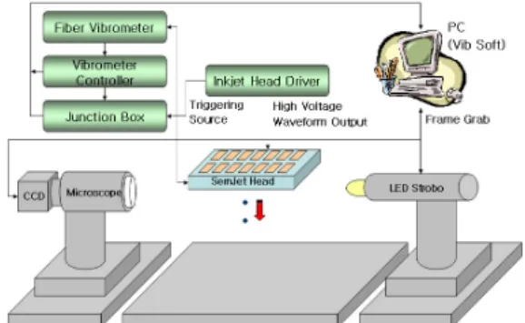
f are 2 ㎲, 3 ㎲ and 5 ㎲, respectively. viscosity and surface tension of ink is 4.8 cPs and 0.025 N/m, respectively. In order to observe the droplet velocity and volume the stroboscopic visualization system as shown in Fig. 5 is used. Comparison between simulation result and measured one is shown in Table 1. Both the predicted droplet velocity and the drop volume match well with the experimental results. As a result, the accuracy of 1D lumped model is verified. Some difference between the measured data and the theoretical one results from inaccurate resistance. Due to the complex geometry of flow passage, the simple analytical equation used for calculating lumped parameter is not implemented.
Therefore, alternatively, 3D modeling approach can be applied for improving accuracy of 1D lumped model.
Fig. 1 Structure of piezoelectric inkjet head.
Fig. 2 Equivalent circuit representation of a piezo –driven inkjet system.
Fig. 3 Simulated displacement corresponding to an applied voltage for calculation of the compliance of vibrator and KVtoP for lumped element analysis.
Fig. 4 The trapezoidal driving waveform
Figure 5. The schematic diagram of visualization equipment
Table 1. Comparison between simulation result and measurement.
1 D analysis Measurement Error(% ) Droplet
volume[p1 ] 24.2 27.5 12
Droplet
velocity[m/s] 3.6 3.8 6
3. Results and discussion
By using 1D lumped model, the performance of inkjet print head is evaluated with the variation of restrictor geometry. When the voltage waveform as depicted in Fig.6 is applied, the performance has been evaluated. The waveform consists of five parts of first falling time(T1), first holding time(T2), rising time(T3), second holding time(T4) and second falling time(T5).
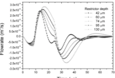
The operating driving voltage travels from -15 V to 40V and T1, T2, T3, T4 and T5 are 1.5, 6.5, 1.5, 14.5 and 1.5 ㎲, respectively. In this study, viscosity and surface tension of ink is 4.8 cPs and 0.025 N/m, respectively. By using 1D analysis, the flow rate at nozzle is characterized with the variation of restrictor depth as shown in Fig. 7. Since the decrease in restrictor depth causes the flow resistance at restrictor to increase, the fluid moving into nozzle increases.
Therefore, as depicted in Fig. 8, the droplet volume increases with variation of restrictor depth. On the other
hand, the Helmholtz resonance frequency of inkjet printing head decreases according to the reduction of the restrictor depth as shown in Fig. 9. This phenomenon influences the characteristics of jetting frequency of inkjet head. Fig. 10 shows the droplet volume variation with respect to jetting frequency up to 20 kHz. At 130 ㎛ of the restrictor depth, droplet volume does not change with variation in ejection frequency. However, as the restrictor depth is 42mm, the droplet volume dramatically changes with variation in jetting frequency due to insufficient ink supply.
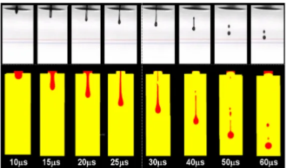
To explore the liquid ejection behavior which can not be performed by 1D analysis, three-dimensional computation model for inkjet model is studied with a commercial computational fluid dynamics solver of FLUNETTM. To reduce the error between measured data and simulated one, an accurate input data should be provided. Therefore, the bending deflection of the piezoelectric vibrator according to the applied driving waveform is measured by means of a Laser Doppler Vibrometer (LDV) at the top of the pressurization chamber. The visual observation of an ejected droplet at the real printing head is compared with the graphic evaluation of the simulation results as shown in Fig. 11.
As can be seen in the figure, a comparison between the simulation results and the photographical images of the ejected droplets shows good agreement with time sequence. The developed 3D model can be used for understanding the effect of the driving waveform on the increase of droplet velocity, reduction of droplet size and elimination of satellite droplet for the industrial application.
Fig. 6 Waveforms of the driving voltages signal applied to the inkjet head
Fig. 7 Flow rate at nozzle with variation of restrictor depth
Fig. 8 Velocity and droplet volume change with variation of restrictor depth
Fig. 9 Helmholtz resonance frequency change according to the variation of restrictor depth
Fig. 10 Droplet volume change according to variation of jetting frequency
Fig. 11 Comparison between simulation results and photographical images with time sequence
4. Droplet control process
Repeatability of circuitry fabrication using inkjet printing technique is closely related to the formation of steady, satellite-free droplets. Therefore, the ability to form small and stable droplets with a same size, constant velocity must be taken into consideration for realizing fine and precise conductive patterns.
However, every nozzle has inequality in ejecting performance due to fabrication error of the head, surface condition of nozzle plate and ink filling state within the chamber and so on. It can produce different droplet velocity and volume. For this reason, deviations between nozzles should be avoided to guarantee the precise line formation. Fig. 12 illustrates the schematics of the iterative droplet control process. First, measure the all ejecting status of every nozzle with developed drop inspection system called DropAnalyzerTM and analyzes the measuring data. Based on the analysis, calculate the compensated voltage to remove the deviation within the desired tolerance. Calibrated jetting results are shown in Fig. 13. Velocity uniformity between nozzles is dramatically improved by applying droplet control process. In addition, it can solve the volume variation affecting the line width. Typical volume tolerance achieved by the piezoelectric inkjet printhead across the 64 nozzles is 5 to 10 %. The droplet control system utilizes the data from the drop inspection to change the waveform repeatedly to each
individual nozzle to achieve the predetermined drop volume and velocity. Fig. 14 shows the drop velocity and volume of 64 nozzles in printhead before and after tuning using a droplet control system. As can be seen in the Figure, velocity deviations are minimized to 2.2 % while the 10 % at initial state. Also, the uniformity of drio volume has improved simultaneously.
Fig. 12 Flow chart of the droplet control process
(a) before DPN
(b) after DPN
Fig. 13 Enhancement of the ejecting performance by droplet control process
(a) drop velocity
(b) drop volume
Fig. 14 Compensated droplet velocity and droplet volume across the inkjet print head
4. Conclusion
A modeling approach combining 1D lumped analysis and 3D analysis has been developed and applied to industrial inkjet print head design. The result shows that 1D lumped analysis has advantage of evaluating and optimizing the performance of the inkjet print head. And, the droplet formation process achieved by 3D analysis is expected to help to understand the influence of the driving voltage waveform on the reduction of droplet size and elimination of satellite droplet.
Also, the experimental droplet control process has been successfully developed in order to improve the
uniformity of droplet velocity and volume for realizing precise line patterns for the application of direct writing.
References
[1] Stephen F. Pond, Inkjet Technology and Product Development Strategies, Torrey Pines Research, Carlsbad,(2000)
[2] Henning Sirringhaus, Tatsuya Shimoda, MRS Bulletin 28, 802 (2003)
[3] Sang-Wook Lee, Hyeon-Cheol Kim, Keon Kuk and Yong-Soo Oh, “A Monolithic Inkjet Print Head:
Domjet,” IEEE, (2001)
[4] Tatsuya Shimoda, Kastsuyuki Morii, Shunichi Seki, and Hirosh Kiguchi, MRS Bulletin 28, 821 (2003)
[5] Max Shtein, Peter Peumans, Jay B. Benziger, and Stephen R. Forrest, Adv. Mater. 16, 1615, (2004).