Optimal Design of 3D Printer based Piezo-driven Vertical Micro-positioning Stage
김 정 현
† Jung Hyun Kim
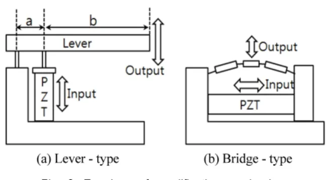
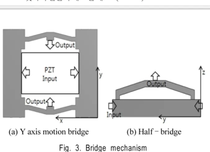
†Abstract This paper presents the development of a 3D printer based piezo-driven vertical micro-positioning stage. The stage consists of two flexure bridge structures which amplify and transfer the horizontal motion of the piezo-element into vertical motion of the end-effector. The stage is fabricated with ABS material using a precision 3D printer. This enables a one-body design eliminating the need for assembly, and significantly increases the freedom in design while shortening fabrication time. The design of the stage was optimized using response surface analysis method. Experimental results are presented which demonstrate 100nm stepping in the vertical out-of-plane direction. The results demonstrate the future possibilities of applying 3D printers and ABS material in fabricating linear driven motion stages.
Keywords 3D printer, piezo, motion stage, flexure hinge, flexure, motion control, ABS
Received : Oct. 29. 2016; Revised : Jan. 12. 2017; Accepted : Feb. 20. 2017
※This research was supported by Kyungsung University Research Grants in 2016
†