Vol.19, No.1, (2017), pp.30~35 https://doi.org/10.9714/psac.2017.19.1.030
```
1. INTRODUCTION
A YBa2Cu3O7-y (YBCO) superconductor has a high superconducting critical temperature (Tc) of 93 K [1], and a high critical current density (Jc) at the magnetic fields [2-4].
The electric transport capacity of a YBCO superconductor is dependent on the microstructure, especially the size and density of the micro-defects present in the superconducting grain. Some of the defects effectively trap the magnetic flux at high magnetic fields [5-8].
In addition to microstructural defects, the size of the shield current loop (the grain size of YBCO) influences the magnetic levitation properties of superconductors. The larger the grain size, the larger the magnetic levitation force. Large grain YBCO bulk superconductors with high magnetic levitation force can be fabricated by melt growth processes that utilizes the incongruent melting and a peritectic reaction [2-4, 9,10]. Among the melt growth processes developed thus far, the TSMG process is known to be the most effective process for producing a large grain YBCO superconductor [11-13]. Using the TSMG process, a single grain YBCO bulk superconductor with a diameter of several centimeters can be produced.
Because of the high magnetic levitation force and high trapped magnetic field of a TSMG-processed YBCO superconductor, a bulk superconductor is used as a high-field superconducting permanent magnet [14,15] and
a high-efficiency frictionless bearing material [16,17].
The magnetic levitation force (F) of the superconductors is given by eq. (1) [18],
F= m(dH/dx), m=Mv, M=JcAr (1)
where m is a magnetic moment of a superconductor, M is a magnetic moment per unit volume, v is a volume, A is a constant regarding the sample geometry, Jc is a critical current density of a superconductor, and r is the radius of a shielding current loop. This means that the grain size and Jc of the superconductor are two important factors determining the magnetic levitation force of a superconductor.
In addition to the grain size and Jc of the superconductor, other experimental parameters affect the magnetic levitation force of the superconductor. They are the effective dimensions of the bulk superconductors, the size and the magnetic flux density of the permanent magnet, and the cooling method (field cooling or zero field cooling).
In order to use superconductors in practical applications such as superconducting flywheel energy storage devices [16] and water purifiers [17], the above parameters should be optimized.
This study aims to understand the specifications of single grain YBCO bulk superconductors required to maximize the magnetic levitation and field-trapping capabilities of superconductors. The effects of the
Orientation and thickness dependence of magnetic levitation force and trapped magnetic field of single grain YBa
2Cu
3O
7-ybulk
superconductors
Y. Junga, S. J. Goa, H. T. Jooa, Y. J. Leeb,c, S.-D. Parkb, B.-H. Junb, and C.-J. Kim*,b
a Korea Science Academy of Korea Advanced Institute of Science and Technology, Pusan, Korea
b Neutron Utilization Technology Division, Korea Atomic Energy Research Institute, Daejeon, Korea
c Sungkyunkwan University, Suwon, Korea
(Received 20 February 2017; revised or reviewed 13 March 2017; accepted 14 March 2017)
Abstract
The effects of the crystallographic orientation and sample thickness on the magnetic levitation forces (F) and trapped magnetic field (B) of single grain YBCO bulk superconductors were examined. Single grain YBCO samples with a (001), (110) or (100) surface were used as the test samples. The samples used for the force-distance (F-d) measurement were cooled at 77 K without a magnetic field (zero field cooling, ZFC), whereas the samples used for the B measurement were cooled under the external magnetic field of a Nd-B-Fe permanent magnet (field cooling, FC). It was found that F and B of the (001) surface were higher than those of the (110) or (100) surface, which is attributed to the higher critical current density (Jc) of the (001) surface. For the (001) samples with t=5–18 mm, the maximum magnetic levitation forces (Fmaxs) of the ZFC samples were larger than 40 N. About 80% of the applied magnetic field was trapped in the FC samples. However, the F and B decreased rapidly as t decreased below 5 mm. There exists a critical sample thickness (t=5 mm for the experimental condition of this study) for maintaining the large levitation/trapping properties, which is dependent on the material properties and magnitude of the external magnetic fields.
Keywords: YBCO superconductor, Single grain, Magnetic levitation forces, Trapped magnetic fields, Crystallographic orientation, Thickness
* Corresponding author: [email protected]
Y. Jung, S. J. Go, H. T. Joo, Y. J. Lee, S.-D. Park, B.-H. Jun, and C.-J. Kim
crystallographic orientations and sample thickness of the superconductor on the magnetic levitation forces and the trapped magnetic fields at 77 were examined.
2. EXPERIMENTAL PROCEDURE
The large single grain YBCO bulk superconductors were fabricated by a TSMG process including power compaction, seeding and melt growth heat treatment.
Detailed heat treatment schedules for preparing the samples have been well described in other studies [9]. The grain size of the prepared samples was 30–50 mm.
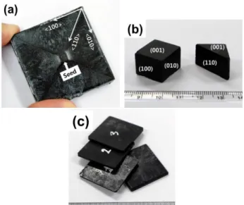
Fig. 1(a) shows the top surface of a rectangular single-grain sample. As shown in the figure, four facet lines are developed diagonally on the top surface of the sample. These four lines start at the seed located at the center of the sample and meet the four corners of the sample. The orientations of the x-shaped lines are the YBCO <110> orientations, which is known to be caused by the anisotropic growth of YBCO grain [5]. A single x-shaped pattern is formed on the top surface of the sample, which indicates that the sample is a single grain and the top surface is perpendicular to the c-axis of YBCO.
According to the orientation information obtained from the facet lines of the top surface, the large single grain YBCO bulk superconductor was cut along the <100> and
<110> orientations using a diamond saw to obtain (001), (100) or (110) cut surfaces (Fig. 1(b)). In addition, the samples whose top surface is (001) and thickness is different were prepared to understand the thickness effects on the magnetic levitation force and field-trapping properties (see Fig. 1(c)).
The X-ray diffraction analysis was carried out to identify the crystallographic orientations of the cut surfaces.
Fig. 2 shows the XRD patterns of the top, cut surface and side of Fig. 1(b). Similar to the result of the orientation
Fig. 1. Photos of (a) top surface of a single grain YBCO superconductor, (b) samples cut with <110> and <100>
orientation of YBCO and (c) samples whose top surface is a (001) plane and whose thickness is different.
20 30 40 50 60 70 80
Top
Diagonal plane
(100) (200)
(003) (009)
(007)
(006)
(005)
Intensity (Arb. unit)
2 Theta/degree
(100) surface (110) surface (001) surface
(220)
(110)
Side
Fig. 2. X-ray diffraction patterns of the top, side and cut surface of the single grain YBCO sample.
Fig. 3. Magnetic levitation force measurement system.
analysis for the top surface facet lines of Fig. 1, the top, side and diagonal cut surface correspond to the (00l), the (0l0) and the (110) planes, respectively of the orthorhombic crystal structure. Not illustrated here, all of the top surfaces of Fig. 1(c) were identified as (001) surfaces.
In this experiment two important properties of magnetic levitation force and trapped magnetic field at 77 K were measured. To measure the force-distance curves, the specimens were cooled to 77 K in a magnetic-free environment (zero field cooling, ZFC) and the permanent magnets were approached to the cooled superconductors (see Fig. 3). The maximum magnetic levitation force (Fmax) is defined as the force when the distance (d) between the superconductor and the permanent magnet is 0.1 mm.
A trapped magnetic field (B) measurement was performed on field-cooled samples. The specimen was placed on a metal plate and fixed with a specially designed jig (see Fig. 4(a)). Permanent magnets with a diameter of 30 mm and a surface field of 4.9 kG (Fig. 4(b)) were placed on the sample, and liquid nitrogen was poured thereon to cool the sample to 77K (field cooling, FC). When the temperature of the sample reached 77 K, the permanent magnet placed on the superconductor was removed, and the magnetic force trapped in the superconductor was measured on the top surface using a hall probe (Fig. 4(c)).
31
Fig. 4. Trapped magnetic field measurement system: (a) sample holder, (b) permanent magnet-sample arrangement for field trapping, and (c) hall probe.
The maximum trapped magnetic field (Bmax) was defined as the maximum value in the measured magnetic field distribution curve.
3. RESULTS AND DISCUSSION
3.1. Crystallographic orientation vs. magnetic levitation force
Fig. 5 shows a typical example of a F-d hysteresis curve at 77 K of the ZFC sample. As can be seen in the figure, the repulsive magnetic force (F) induced by the Meissner effect of the superconductor is nearly zero until d becomes 10 mm. However, F increases exponentially as d decreases below 10 mm and Fmax is 23.2 N. In the F-d hysteresis curve, the attractive force caused by the magnetic flux trapped in a superconductor is small enough to ignore.
The F-d curves at 77 K were estimated on the (001), (110) and (100)/(010) planes of the ZFC samples using a permanent magnet with a surface field of 4.2 kG and diameters of 10 mm. The Fmax estimated in the F-d curves are shown in the histogram of Fig. 6. The values of Fmax(001), Fmax(100), Fmax(010) and Fmax(110) are 35.4 N, 25.5 N, 21.4 N, and 23.2 N, respectively. Among Fmax(hkl), the value of Fmax(001) is the highest, which is approximately 30%
higher than that of Fmax(010) or Fmax(110). The levels of Fmax(100), Fmax(010) and Fmax(110) are almost similar each other.
This result implies that the permanent magnet and (001) plane of the superconductor should meet vertically in order to obtain a high magnetic levitation force.
The difference in Fmax among the (hkl) planes can be explained in terms of Jc at each crystallographic planes of YBCO. All test specimens are monocrystalline, and there is no high-angle grain boundary, which is a factor that allows magnetic forces to easily pass through and eventually lower the magnetic levitation force. Therefore, the main factor affecting the magnetic levitation force of superconductors in this experiment is Jc at each crystallographic plane. It was reported that Jc of the (001) plane was the highest among the crystallographic planes of YBCO [19]. This is because the (001) plane has the largest number of copper-oxygen bonds that make up the flow of
0 10 20 30 40 50
0 5 10 15 20 25
Fmax=23.2 N
Magnetic levitation force (N)
Distance (mm)
Zero field cooled at 77 K
Fig. 5. A typical example of a F-d curve of a large grain YBCO bulk superconductor.
35.378
25.48
21.364 23.226
0 10 20 30 40
(010) (100) (110)
(001)
Max. magnetic levitation force (N)
at 77 K Zero field cooled
Crystallographic plane of YBCO
Fig. 6. Maximum magnetic levitation forces at 77 K of the crystallographic surfaces of the ZFC samples.
supercurrents compared to other crystallographic planes (the coherence length, ξ at the (001) plane is much longer than that at the other planes [20]).
3.2. Crystallographic orientation vs. trapped magnetic field Fig. 7 shows the trapped magnetic field map of the (100) surface of the FC sample measured using a Nd-B-Fe permanent magnet with a surface field of 4.9 kG and a diameter of 30 mm. A single peak is observed at the center of the trapped field contour map. One peak appears at the center of the map. This is a typical form of the single grain superconductor. The discontinuities that often appear due to the presence of microcracks or high angle grain boundaries do not appear in the trapped field map. The maximum trapped field (Bmax) at the peak point is 1.21 kG.
5 10
15 -0.2
0.0 0.2 0.4 0.6 0.8 1.0 1.2
1 0 2 0
(100) surface at 77 K
Trapped magnetic field (kG)
Y-Axis (mm) X-Axis (mm)
-0.08500 0.07812 0.2412 0.4044 0.5675 0.7306 0.8937 1.057 1.220
Fig. 7. Trapped magnetic field contour of the (100) surface of single grain YBCO bulk superconductor.
Y. Jung, S. J. Go, H. T. Joo, Y. J. Lee, S.-D. Park, B.-H. Jun, and C.-J. Kim
TABLE I.
MAXIMUM TRAPPED MAGNETIC FIELD AND % RATIO FOR THE APPLIED MAGNETIC FIELD OF THE CRSYTALLOGRAPHIC (HKL) SURFACES. Crystallographic
Plane (hkl)
Maximum trapped magnetic field, Bmax (kG)
% ratio for the applied magnetic field
(001) 2.58 49.14
(100) 1.21 23.05
(010) 0.80 15.24
(110) 1.02 19.43
Not shown here, a trapped magnetic field map of the (010), (110) and (001) surfaces also showed a single grain mode similar to that of the (100) surface in Fig. 7. The values of Bmax of each surfaces are summarized at TABLE I. The values of Bmaxs of the (010), (110) and (001) surfaces are 0.8 kG, 1.02 kG and 2.58 kG, respectively. The value of the trapped magnetic field of the (001) plane is the largest among the measured planes. Forty-nine percent of the applied magnetic field was trapped in the (001) surface, which is comparable to the Bmax values of other surfaces that are smaller than 25%. This result agrees well with the F-d measurements on the corresponding crystallographic surfaces of Fig 6.
3.3. Sample thickness vs. magnetic levitation forces Fig. 8 shows the F-d curves measured at 77 K for the (001) samples with various values of t. A Nd-B-Fe permanent magnet with a surface field of 4.9 kG and a diameter of 30 mm was used for the levitation force measurement. As can be seen in this figure, all samples show typical F-d hysteresis curves where a magnetic repulsive force increases exponentially as d decreases.
The values of Fmax of the samples with t=12.9 mm, t=5.1 mm, t=4.0 mm, and t=2.7 mm are 44 N, 42 N, 36 N and 27.5 N, respectively. The difference in Fmax between t=12.9 mm and t=5.1 mm is very small as 0.2 N (4.5%), whereas the difference in Fmax between t=12.9 mm and t=2.7 mm is large as 16.5 N (37.5%). Unlike other samples, the attractive force component of 1.6 N appears at d=14 mm in the F-d curve of the sample with t=2.7 mm. The attractive force component is produced by the magnetic fields trapped inside the superconductor, which appears well in the FC sample, and its size is relatively large compared to the ZFC sample [20]. Alternatively, the attractive force appears in the polycrystalline samples with many grain boundaries where a magnetic flux easily penetrates. Therefore, this result indicates that when the thickness of the superconductor is thin, some of the magnetic field enters the inside of the superconductor and is trapped.
The values of Fmax as a function of t for all measured (001) samples are shown in Fig. 9. For the samples with t=5 mm–18 mm. the values of Fmax are almost constant at about 40 N. However, as t decreases below 5 mm, Fmax decreases rapidly. The surface superconducting layer of a certain thickness seems to determine the magnetic levitation force of the bulk superconductors, and its value is 5 mm for our study. This result agrees well with a previous work that showed a transition of the magnetic levitation forces at t=6 mm [21].
0 10 20 30 40 50
0 10 20 30 40 50
Zero field cooled at 77 K
t = 2.7 mm t = 4.0 mm t = 5.1 mm t = 12.9 mm
Magnetic levitation force (N)
Distance (mm)
Fig. 8. F-d curves of the (001) surfaces of the ZFC samples with various values of t.
0 5 10 15 20
0 10 20 30 40 50
Magnetic levitation force (N)
Sample thickness (mm) Zero field cooled at 77 K
Fig. 9. Fmax as a function of t of the (001) surface of the ZFC samples.
3.4. Sample thickness vs. trapped magnetic field
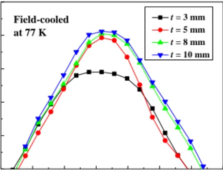
Fig. 10 shows the B-d curves at 77 K measured for the (001) samples with various t. A Nd-B-Fe permanent magnet with a surface field of 4.9 kG and a diameter of 30 mm was used for field trapping. All B-d curves show a single grain map having a peak point at the center of the maps. The values of Bmax at t=10 mm, t=8 mm, t=5 mm and t=3 mm are 4.09 kG, 4.02 kG, 3.87 kG and 2.86 kG, respectively. These values correspond to 83.4%, 82.0%, 78.9% and 58.3% of the magnetic field (4.9 kG) of the permanent magnet used. Approximately 80% of the applied magnetic field is trapped in the samples with t>5 mm.
5 10 15 20 25 30 35 40
0 1 2 3 4 5
Trapped magnetic field (kG)
Distance (mm)
t = 3 mm t = 5 mm t = 8 mm t = 10 mm Field-cooled
at 77 K
Fig. 10. B-d curves of the (001) surfaces of the FC samples with various t.
33
0 5 10 15 20 2.5
3.0 3.5 4.0 4.5
Maximum trapped magnetic field (kG)
Sample thickness (mm)
Field cooled at 77 K
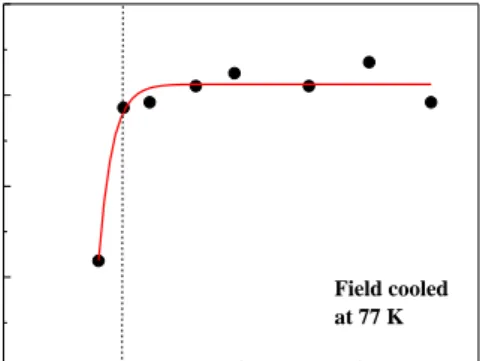
Fig. 11. Bmax as a function of t of the (001) surfaces of the FC samples.
The values of Bmax of the (001) samples with various t is shown in Fig. 11. Similar to the variation of Fmax with t of Fig. 9, Bmax of the samples is almost constant until t decreases to 5 mm. As t decreases below 5 mm, however, Bmax decreases rapidly. The critical sample thickness for trapping the large magnetic field is also 5 mm for the experimental condition of this study.
This study showed that there exists a critical sample thickness for a large F and B of YBCO bulk superconductors. This thickness appears to be related to the properties of the material used. The samples used in this study are large single grain bulks with a size of 20-40 mm. A sufficiently large shielding current loop was created for the external magnetic field of the permanent magnet, which would have made a significant contribution to the magnetic levitation force of the superconductor.
Moreover, the values of Jc of the superconductor is as large as 1.5×10⁴ A/cm2 at a magnetic field of 5.0 kG [22], because there is no high angle grain boundaries through which a magnetic field passes. Even if the shielding current flows strongly on the surface of the superconductor, however, if the external magnetic field is large and the thickness of the superconductor is small, a certain amount of the magnetic field enters in the superconductor and is trapped in the superconductor. For these reasons, the critical thickness of the superconductor varies depending on the characteristics of the material and experiment.
With respect to the amount of magnetic field trapped in the superconductor, the presence and the density of micro-defects pinning the magnetic field are important. As already reported in many references [5-7], there are many microdefects such as twins, dislocations, stacking faults, inclusion particles and oxygen deficiencies inside superconductors produced through the melt growth process. They act effectively in trapping the magnetic flux inside the superconducting grains of the FC samples. The high Jc, the large grain and the small defects present inside the superconductor are attributed to the large trapped magnetic fields of the FC samples.
The experimental results of this study will provide useful information (Jc, the crystallographic orientation and dimension of the superconductors, the magnitude of the external magnetic fields, and so on) for designing the superconducting bulk used in superconducting
applications such as a superconducting flywheel energy storage system, the magnetic transportation, and superconductor bulk magnets.
4. CONCLUSIONS
To optimize the parameters of the bulk superconductors that are used in application devices, the effects of the crystallographic orientation and sample thickness on the magnetic levitation force (F) and the trapped magnetic field (B) were examined. The values of F and the B at 77 K were dependent on the crystallographic orientation of YBCO. The value of Fmax of the (001) surface was 30%
larger than those of the (100) and (110) surfaces. The value of Bmax of the (001) surface was about twice that of the other surfaces. The excellent magnetic levitation/field-trapping properties of the (001) surface was explained in terms of the high Jc of the (001) plane in an orthorhombic crystal structure [17]. The variations in F and B as a function of t were also estimated for the (001) sample. For t=5–18 mm, the values of Fmax and Bmax of were similar to each other. However, the values of Fmax and Bmax decreased rapidly, as t decreased below 5 mm. There exists a critical sample thickness for maintaining the large magnetic levitation/trapping properties (t=5 mm for the (001) sample for the experimental conditions of this study).
The variations of F and B with the crystallographic orientation and sample thickness were explained in terms of Jc, the grain size and the micro-defects within the bulk superconductors used in this study.
ACKNOWLEDGEMENTS
This work was funded by the Ministry of Science, ICT and Future Planning (MSIP), and also supported by the National Research Foundation Grant (NRF-2013M2A8A 1035822) from Ministry of Science, ICT and Future Planning (MSIP) of Republic of Korea.
REFERENCES
[1] M. K. Wu, J. R. Ashburn, C. J. Torng, P. H. Hor, R. L. Meng, L. Gao, Z.J. Huang, Y. Q. Wang, and C.W. Chu, “Superconductivity at 93 K in a New Mixed-Phase Y-Ba-Cu-O Compound System at Ambient Pressure,” Phys. Rev. Lett., vol. 58, pp. 908-910, 1987.
[2] S. Jin, T. H. Tiefel, R. C. Sherwood, R. B. van Dover, M. E. Davis, G.
W. Kammlott, and R. A. Fastnacht, “Melt-textured growth of polycrystalline YBa2Cu3O7−δ with high transport Jc at 77 K,” Phys.
Rev. B37, pp. 7850-7853, 1988.
[3] K. Salama, V. Selvamanickam, L Gao, and K. Sun, “High current density in bulk YBa2Cu3Ox superconductor,” Appl. Phys. Lett., vol. 54, no. 23, pp. 2352-2354, 1989.
[4] M. Murakami, M. Morita, K. Doi, and K. Miyamoto, “A New Process with the Promise of High Jc in Oxide Superconductors,” Jpn.
J. Appl. Phys, vol. 28, no.7, pp. 1189-1194, 1989.
[5] C. J. Kim and G. W. Hong, “Defect formation, distribution and size reduction of Y2BaCuO5 in melt-processed YBCO superconductors,”
Supercond. Sci. Technol., vol. 12, pp. R27-R41, 1999.
[6] C. J. Kim, K. B. Kim, I. H. Kuk, G. W. Hong, Y. S. Lee, and H. S.
Park, “Microstructure change during oxygen annealing and the effect on the levitation force of melt-textured Y-Ba-Cu-O superconductors,”
Supercond. Sci. Technol., vol. 10, pp. 947-954, 1997.
Y. Jung, S. J. Go, H. T. Joo, Y. J. Lee, S.-D. Park, B.-H. Jun, and C.-J. Kim
[7] C. J. Kim, Y. S. Lee, H. S. Park, I. H. Kuk, T. H. Sung, J. J. Kim, and G. W. Hong, “Oxidation induced formation of a-b planar defects in melt-textured YBa2CuO7-y containing Y2BaCuO5 inclusions,”
Physica C, vol. 276, pp. 101-108, 1997.
[8] Y. J. Lee, J. H. Choi, B.-H. Jun, J. Joo, C. S. Kim, and C.-J. Kim,
“Effects of electron beam irradiation on the superconducting properties of YBCO thin films,” Prog. Supercond. Cryog. vol. 18, no.
4, pp. 15-20, 2016.
[9] Y. A. Jee, G. W. Hong, T. H. Sung, and C. J. Kim, “Control of the Growth rate of YBa2Cu3Ox single-domained crystal by applying two-step undercooling in top-seeded met growth,” Physica C, vol.
304, pp. 255-264, 1998.
[10] A. Goyal, K. B. Alexander, D. M. Kroeger, P. D. Funkenbusch, and S.
J. Burns, “Solidification of YBa2Cu3O7-δ,” Physica C, vol. 210, pp.
197-212, 1993.
[11] Y. Shi, N. H. Babu, and D. A. Cardwell, “Development of a generic seed crystal for the fabrication of large grain (RE)-Ba-Cu-O bulk superconductors,” Supercond. Sci. Technol., vol. 18, pp. L13-L16, 2005.
[12] David A. Cardwell, “Processing and properties of large grain (RE)BCO,” Mater. Sci. Eng. B, vol. 53, pp. 1-10, 1998.
[13] Y. A. Jee, C.-J. Kim, T.-H. Sung and G.-W. Hong, “Top seeded melt growth of Y-Ba-Cu-O superconductor with multiseeding,” Supercond.
Sci. Technol., vo. 13, pp. 195-201, 2000.
[14] J. H. Durrell., A. R. Dennis., J. Jaroszynski, M. D. Ainslie, K. G. B.
Palmer, Y-H. Shi, A. M. Campbell, J. Hull, M. Strasik, E. Hellstrom, and D. A. Cardwell, “A Trapped Field of 17.6 T in Melt-Processed, Bulk Gd-Ba-Cu-O Reinforced with Shrink-Fit Steel,” Supercond. Sci.
Technol., vol. 27, 082001, 2014.
[15] M. Tomita, and M. Murakami, “High-temperature superconductor bulk magnets that can trap magnetic fields of over 17 tesla at 29 K,”
Nature, vol. 421, pp. 517-520, 2003.
[16] M. Strasik, J. R. Hull, J. A. Mittleider, J. F. Gonder, P. E. Johnson, K.
E. McCrary and C. R. McIver, “An overview of Boeing flywheel energy storage systems with high-temperature superconducting bearings,” Supercond. Sci. Technol. vol. 23, p. 034021, 2010.
[17] T. Oka, H. Kanayama, S. Fukui, J. Ogawa, T. Sato, M. Ooizumi, T.
Terasawa, Y. Itoh, and R. Yabuno, “Application of HTS bulk magnet system to the magnetic separation techniques for water purification,”
Physica C, vo. 468, no. 15-20, pp. 2128-2132, 2007.
[18] M. Murakami, T. Oyama, H. Fujimoto, T. Taguchi, S. Gotoh, Y.
Shiohara, N. Koshizuka, and S. Tanaka, “Large Levitation Force due to Flux Pinning in YBaCuO Superconductors Fabricated by Melt-Powder-Melt-Growth Process,” Jpn. J. Appl. Phys, vol. 29, no.
11, pp. L1991-L1994, 1990.
[19] M. Murakami, Melt processed high-temperature superconductors, 1st ed., chapter 6, Singapore: World Scientific, 1992, pp. 127-131.
[20] H. Jiang, T. Yuan, H. How, A. Widom, and C. Vittoria,
“Measurements of anisotropic characteristic length in YBCO films at microwave frequencies,” J. Appl. Phys., vol. 73, no. 10, pp.
5865-5867, 1993.
[21] Y. S. Lee, H. S. Park, I. H. Kuk, G. W. Hong, and C. J. Kim,
“Levitation force of melt–textured single- and multi-domain YBaCuO superconductors,” Korean J. Mater. Res., vol. 8, pp. 105-113, 1998.
[22] C.-J. Kim, J. H. Lee, S.-D. Park, B.-H. Jun, S. C. Han and Y. H. Han,
“Y2BaCuO5 buffer block as a diffusion barrier for samarium in top seeded melt growth processed YBa2Cu3O7–y superconductors using a SmBa2Cu3O7−d seed,” Supercond. Sci. Technol., vol. 24, p. 015008, 2011.
35