A Study of Supersonic Combustion using Various Liquid Hydrocarbon Fuels
Susumu Hashimoto*, Ayumu Hiramoto*, Mitsuhiro Tsue*, Michikata Kono*
Yuta Ishikawa**, Shunsuke Suzuki** and Yasushige Ujiie**
* Department of Aeronautics and Astronautics, University of Tokyo
** Department of Industrial Technology, Nihon University 7-3-1 Hongo, Bunkyo-ku, Tokyo, 113-8656, Japan
[email protected]
Keywords: Scramjet, Liquid Hydrocarbon, Cetane Number
Abstract
Liquid hydrocarbon fuels are gathering increasing attention as candidates for a scramjet engine fuel.
Experimental researches on supersonic combustion of kerosene have been conducted in model scramjet combustors. Through these works, understanding of combustion characteristics of kerosene have been revealed on some level, and so we decided to work on other kinds of liquid hydrocarbon fuels in order to explore effects of fuel properties on supersonic combustion performances, especially self-ignition and flame-holding. In addition, comparing the results of new fuels with kerosene, the relationship between fuel properties and supersonic combustion characteristics was discussed.
Nomenclature T
0: total temperature of main air flow Φ : equivalence ratio
P
b: static pressure of barbotage gas P
w: wall static temperature x : distance from the backward step
Introduction
Scramjet engine has been investigated as a candidate of propulsion device of hypersonic vehicle.
As its fuel, hydrogen and hydrocarbons have been considered generally. While hydrogen has many advantages in scramjet combustors, its low energy density is greatly disadvantageous for orbital vehicles.
So, we decided to adopt liquid hydrocarbons because of their high energy density. However, they are inferior to hydrogen in diffusivity and reactivity, thus, more difficult to burn under extremely rapid flow in scramjet combustor. It is necessary to improve their supersonic combustion for realization of the liquid hydrocarbon scramjet engine.
We have conducted a series of experiments of supersonic combustion of kerosene varying injection method and combustor configuration. Through them, we succeeded in some improvement of supersonic combustion behavior of kerosene. For the next step, we considered it would be important to know effects
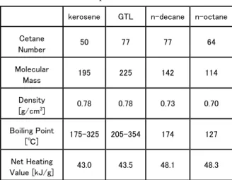
of properties of liquid hydrocarbon fuel on supersonic combustion characteristics. Among many properties, we focused on cetane number. The cetane number is a property of hydrocarbon which indicates how easily the fuel self-ignites in diesel engines. We expected that fuels with high cetane number would be advantageous to supersonic combustion.
We adopted GTL light oil (Gas to Liquid light oil) and because of its much larger cetane number of 77 than 50 of kerosene. It is gathering attention recently as a clean fuel without any sulfur and aromatics.
Because kerosene and GTL light oil are mixtures of many hydrocarbons, it is difficult to obtain their detailed properties and composition. So, we adopted further two single-ingredient hydrocarbons of n-decane (n-C
10H
22) and n-octane (n-C
8H
18) for comparison. Cetane number of n-decane is 77, whichis the same as GTL light oil, and n-octane has 64, which is almost the median of kerosene and GTL light oil. The other properties are also presented in Table 1.
We examined the supersonic combustion performances of the four fuels above in a model scramjet combustor. Additionally, in order to realize the phenomena in the combustor, we conducted several measurements. Through the results of the experiments, we discussed the relationship between the fuel properties and supersonic combustion characteristics.
Table 1 Properties of the fuels
kerosene GTL n-decane n-octane
Cetane
Number 50 77 77 64
Molecular
Mass 195 225 142 114
Density
[g/cm3] 0.78 0.78 0.73 0.70
Boiling Point
[℃] 175-325 205-354 174 127
Net Heating
Value [kJ/g] 43.0 43.5 48.1 48.3
Experimental apparatus
Wind tunnel
We carried out the experiments using the high enthalpy combustion wind tunnel in the University of Tokyo. Its overview is shown in Fig.1. It is a blow- down wind tunnel, and pressurized air from air tank is regulated in 30 [kg/cm
2] by a regulator. After rectified in the rectifier, air flow is heated in the vitiation heater by lean burn of hydrogen. In order to prevent the reduction of oxygen in the air flow, oxygen is added previously in the upstream, and the mole fraction of oxygen after the vitiation is kept to be equal to that of the atmosphere. Then the heated air is accelerated by a two-dimensional nozzle, and flows into the test section of a model scramjet combustor. The air flow condition at the entrance of the combustor is shown in table 2.
Due to the vitiation method, the air flow in the wind tunnel contains some combustion products.
They affect physical values and reactions, therefore combustion in the test section is considered to deviate from actual case somewhat. However, we thought it does not matter because we don’t target to perceive the absolute combustion performances but try to understand the qualitative natures.
Tab.2 Air flow condition at the combustor entrance
Mach Number 2
Total Pressure [MPa] 0.38 Total Temperature [K] 1400-2400
Test section
Configuration of the test section is shown in Fig.2, which is simulated a model combustor of scramjet engine. The cross section of the flow path at the entrance of the combustor is a rectangular with height of 36 [mm] and width of 30 [mm]. The length of the combustor is 400 [mm]. Fuel is injected from an injection hole on the bottom wall at 32 [mm]
downstream from the combustor entrance.
At 18 [mm] downstream from the injection point, a cavity with depth of 12 [mm] and length of 60 [mm] is placed on the bottom wall of the combustor.
It has a ramp of 30 degree at the downstream end in order to prevent the air flow from oscillating. It is known from the past experiments that a large recirculation area is formed in the cavity, and it lengthens the fuel residence time in the combustor and contributes to mixing of air flow and fuel.
Additionally, due to static pressure drop by the abrupt expansion of the flow path, penetration height of the fuel spray increases. When fuel burns in the combustor, the cavity also works as a flame holder.
At the downstream of the exit of cavity, the flow path broadens by a slant of 2 degree on the bottom wall. Without the expansion, the air flow immediately goes into thermal choking due to the heat release of combustion.
Fig.1 Overview of the high enthalpy combustion wind tunnel in the University of Tokyo
Fig.2 Configuration of the model scramjet combustor 30 400
36
Injection 2°
Static Pressure Holes
Cavity 30 400
36
Injection 2°
Static Pressure Holes
Cavity
Combustor Nozzle Heater Rectifier
Airflow
Combustor Nozzle Heater Rectifier
Airflow
Injector
The structure of the fuel injection system is shown in Fig.3. The injector is installed on the bottom wall of the combustor just upstream of the cavity. In the injector, gas flows vertically to the air flow through a hole with the diameter of 4 [mm]. It is called barbotage gas, and we used nitrogen as the barbotage gas, because chemically stable gas was preferable to perceive the effects of barbotage gas itself. Liquid fuel enters the nitrogen flow in the mid-stream through a hole with the diameter of 0.3 [mm]. Thus fuel is injected into the combustor on the nitrogen stream as a two phase flow.
It is known from the past experiments that this injection method excels in atomization and mixing with air flow. Additionally, the penetration height of fuel spray depends on the ratio of momentum between main flow and the fuel spray therefore we can make a preference of the penetration height independently of the amount of fuel only by the static pressure of the barbotage gas.
From the perspective of fuel atomization and penetration, higher static pressure of the barbotage gas seems to be preferable. However, excessively high pressure causes increase of the pressure loss of the main flow and decrease of the fuel which enters the recirculation area in the cavity. We chose 5 [kg/cm
2] as the appropriate static pressure of the barbotage gas and fixed it in all the experiments.
Fig.3 Structure of the injection system
Measurement
On the top wall of the combustor, 23 static pressure holes are set along the air flow direction, and through them wall static pressure distribution is obtained. Whether combustion occurs or not in the combustor is judged by the distribution. The typical static pressure distributions for thermal choking, supersonic combustion and no combustion are shown in Fig.4.
In no combustion mode, there were two sharp pressure rises, upstream one was caused by a bow shock before the fuel injection and downstream one was by a compression wave formed at the end of cavity. In supersonic combustion mode, combustion caused a large pressure rise around the cavity. In
thermal choking mode, the pressure rise increased and shifted upstream. Thermal choke is judged by the static pressure history at the throat of nozzle upstream of the combustor.
When total temperature of the air flow is below 2200 K, quartz window is available to install on the side wall of the combustor. Optical access to the inside of combustor is possible through it. In the case of higher temperature or without particular necessity of optical measurements, brass wall is installed instead.
Fig.4 Typical patterns of static pressure in the combustor ( T
0= 2200 K, P
b= 0.5 MPa, and fuel is GTL light oil )
Results
Self-Ignition performance
Self-ignition performances of the four fuels were examined first. Varying the total temperature of the air flow and the equivalence ratio independently, we observed whether self-ignition would occur or not in each condition with no ignition device. The results are shown in Fig.5. In the diagrams, vertical scale is the equivalence ratio and horizontal scale is the total temperature of the air flow. Conditions in which fuel could self-ignite are indicated by circle plots and conditions in which self-ignition did not arise are indicated by cross plots. While the filled circles mean combustion initiated by self-ignition fell into thermal choking, the empty circles mean combustion without thermal choking. We defined the fuel that self-ignite in lower air flow temperature and lower equivalence ratio as with higher self-ignition performance.
As shown in Fig.5, while any fuel could self- ignite in 2200 and 2400 [K] of the air flow total temperature, could not in lower temperature. In the lowest self-ignition temperature of 2200 [K], the lowest self-ignition equivalence ratio of kerosene is 0.19, that of GTL light oil is 0.16, n-decane is 0.21 and n-octane is 0.17. Hence it is concluded that GTL light oil is the best, n-octane is the second, kerosene is the next and n-decane is the worst in the perspective of self-ignition performance in the model scramjet combustor. In the order, close relationship between cetane number and self-ignition performance is not found. The result doesn’t correspond with our
0 1 0 0 2 0 0 3 0 0
0 . 0 5 0 . 1 0 . 1 5 0 . 2
D is ta n c e fr o m th e S te p [m m ]
Wall Static Pressure [MPa]
T h e r m a l C h o k e S u p e r s o n ic C o m b u s t io n N o C o m b u s t io n
0 1 0 0 2 0 0 3 0 0
0 . 0 5 0 . 1 0 . 1 5 0 . 2
D is ta n c e fr o m th e S te p [m m ]
Wall Static Pressure [MPa]
T h e r m a l C h o k e S u p e r s o n ic C o m b u s t io n N o C o m b u s t io n T h e r m a l C h o k e S u p e r s o n ic C o m b u s t io n N o C o m b u s t io n
expectation that the fuel with larger cetane number should be more advantageous to self- ignition in the supersonic combustor as in the case of diesel engines.
In other words, self-ignition characteristic of a fuel can’t be evaluated by cetane number under extremely fast flow such as in scramjet engines. Similarly, vaporization, which is represented by boiling point, or diffusivity by mean molar mass seems not to correlate directly to self-ignition performance. Some certain constituents might affect the performance more closely than such overall characteristic.
Fig.5 (a) Self-ignition performance of kerosene
Fig.5 (b) Self-ignition performance of GTL light oil
Fig.5 (c) Self-ignition performance of n-decane
Fig.5 (d) Self-ignition performance of n-octane
Self-ignition process
For furthermore detailed discussion of the relation between self-ignition performance and fuel properties it is necessary to understand how self-ignition occurs in the combustor. We believed that dominant factors would be found through observation of the self- ignition process. We recorded the process by a high speed camera. Captured images are shown in Fig.6.
Fuel was kerosene, total temperature of the air flow was 2200 [K], equivalence ratio was 0.26 and shutter speed of the high speed camera was 4000 [fps]. In the pictures, upper and bottom walls and the visible area of the combustor are indicated by white line. And the injection position is also indicated.
It is known from the images that the initial flame is formed around the bottom wall downstream of the cavity. In the area a large separation is caused by the ramp of the cavity end. Additionally, it locates behind the compression wave generated in the cavity exit, therefore pressure and temperature of the air flow in the area is considered to be higher. For these reasons, it is a quite advantageous area to self -ignition.
Formed in such area, the flame propagates upstream in the separation area. The flame progresses to the downstream edge of the cavity, then propagate in the boundary layer on the ramp at the end of cavity.
Consequently, fuel in the cavity starts to burn and its flame propagate upstream. Coinstantaneously, the combustion area progressing into the cavity develops above the cavity as if it upheave the air stream. After progressing furthermore upstream, the flame front eventually reaches the cavity entrance and the combustion results in the stable flame-holding around the cavity. It is known that the self-ignition in the combustor occurs in the gradual process, and it might be the reason why cetane number does not directly relate self-ignition performance.
Considering the process, it is possible to estimate some requirements for self-ignition. First, reactivity of the fuel has to be sufficient for the self-ignition in the separation area and the flame propagation against the air flow. In the perspective, cetane number, which represents reactivity of the fuel, is considered not to be irrelevant. Additionally, combustible mixture has
0.7
0.5 0.6
0.2 0.4
0.1
0 0.3
1800 2000 2200 2400
Equivalence Ratio Φ
Total Temperature of Airflow T0K Thermal Choking Supersonic Combustion No Combustion 0.7
0.5 0.6
0.2 0.4
0.1
0 0.3
1800 2000 2200 2400
Equivalence Ratio Φ
Total Temperature of Airflow T0K Thermal Choking Supersonic Combustion No Combustion
0.7
0.5 0.6
0.2 0.4
0.1
0 0.3
1800 2000 2200 2400
Equivalence Ratio Φ
Total Temperature of Airflow T0K 0.7
0.5 0.6
0.2 0.4
0.1
0 0.3
1800 2000 2200 2400
Equivalence Ratio Φ
Total Temperature of Airflow T0K
0.7
0.5 0.6
0.2 0.4
0.1
0 0.3
1800 2000 2200 2400
Equivalence Ratio Φ
Total Temperature of Airflow T0K 0.7
0.5 0.6
0.2 0.4
0.1
0 0.3
1800 2000 2200 2400
Equivalence Ratio Φ
Total Temperature of Airflow T0K
0.7
0.5 0.6
0.2 0.4
0.1
0 0.3
1800 2000 2200 2400
Equivalence Ratio Φ
Total Temperature of Airflow T0K 0.7
0.5 0.6
0.2 0.4
0.1
0 0.3
1800 2000 2200 2400
Equivalence Ratio Φ
Total Temperature of Airflow T0K
to be formed instantly and exist in the separation area and around the cavity. Accordingly, vaporization and diffusivity also would be important. However, it would require furthermore investigation to identify the dominant factor.
Fig.6 Self-ignition process of kerosene
Flame-Holding
In the conditions of low air flow temperature and low equivalence ratio in which the fuels couldn’t burn by self-ignition, flame-holding performances were examined. In such conditions, fuel is ignited by so-called pilot hydrogen, which is added to the barbotage gas and initiates the combustion. Therefore the pilot hydrogen and hydrocarbon fuel burn in the combustor coinstantaneously. We investigated that combustion would continue or not after eliminating pilot hydrogen from the simultaneous burning of hydrogen and hydrocarbon fuels. Continuance of the combustion without pilot hydrogen is defined as flame-holding and termination of the combustion is defined as quenching.
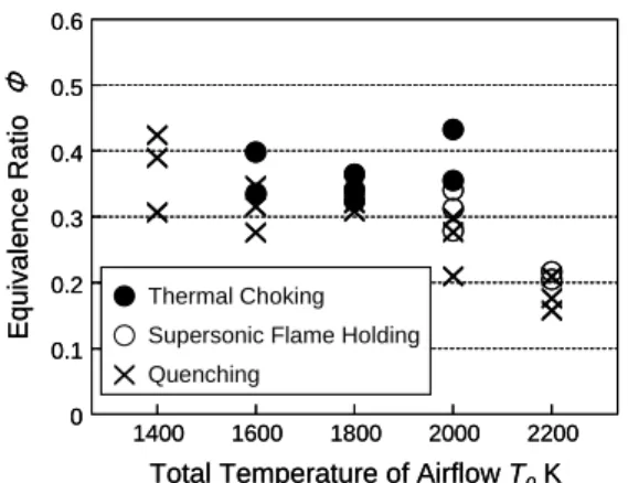
The results of flame-holding experiments on each fuel are shown in Fig.7. As in the case of self-ignition, the vertical scale of the diagrams is equivalence ratio and the horizontal scale is total temperature of the air flow, and the conditions which we succeeded in flame-holding in are indicated by circle plots and the conditions of quenching are cross plots. While the filled circles mean flame-holding with thermal choking, the empty circles mean flame-holding without thermal choking, thus they are significant plots for combustion in scramjet engines. Success of flame-holding without thermal choking in lower air flow temperature and lower equivalence ratio is defined as higher performance.
As shown in Fig.7, even in the conditions of low air flow temperature and low equivalence ratio where self-ignition does not occur flame-holding is possible on any fuels. Only kerosene can not succeed in the air flow temperature of 1800 [K]. The others succeed in the temperature, and the lowest supersonic flame- holding equivalence ratio of GTL light oil is 0.27, that of n-decane is 0.24 and n-octane is 0.29. In 1600 [K] all fuels succeed in flame-holding, but it is always with thermal choking. Accordingly, flame- holding should be evaluated by the data of 1800 [K].
Hence it is concluded that n-decane is the best, GTL light oil is the second, n-octane is the next and kerosene is the worst in the perspective of supersonic self-ignition performance.
The order of flame-holding performance well corresponds with that of cetane number of the fuels.
From the result, it is possible to conclude that large
cetane number seems to contribute to flame-holding
in scramjet combustors. It is interesting that cetane
number which is an indicative property of self-
ignition in diesel engines has the close relationship
with flame-holding in scramjet engines. Flame-
holding is considered to depend on whether chain
reaction of combustion can be sustained or not
against the air flow, therefore cetane number which
represents reactivity of the fuel may be dominant.
Fig. 7 (a) Flame-holding performance of kerosene
Fig. 7 (b) Flame-holding performance of GTL light oil
Fig. 7 (c) Flame-holding performance of n-decane
Fig. 7 (d) Flame-holding performance of n-octane
Conclusion
From the experiments on supersonic combustion characteristics of kerosene, GTL light oil, n-decane and n-octane, the following conclusions are obtained.
1. For self-ignition performance, GTL light oil is the best, n-octane is the second, kerosene is the next and n-decane is the worst.
2. Cetane number is inappropriate for evaluating self-ignition in scramjet combustors.
3. For flame-holding performance, n-decane is the best, GTL light oil is the second, n-octane is the next and kerosene is the worst.
4. Large cetane number is advantageous to flame- holding in scramjet combustors.
Acknowledgment
The present study was performed partly under funding by Grant-in Aid for Scientific Research program of Ministry of Education, Culture, Sports Science and Technology. Special thanks are due to Prof. Takahashi of Department of Engineering, Gifu University for his continuing supports and helpful suggestions.
References
1) Billig, F.S.,:”Research on Supersonic
Combustion,” Journal of Propulsion and Power, Vol.9, No.4, July-Aug.1993 pp. 499-514 2) Waltrup, P.J. , “Liquid-Fueled Supersonic
Combustion Ramjets: A Research Perspective,”
Journal of Propulsion and Power, Vol. 3, No.6, Nov,-Dec. 1987, pp.515-524
3) Takahashi, S., Tanaka, H., Noborio, D., and Miyashita, T., “Mach 2 Supersonic Combustion with Hydrocarbon Fuels in a Rectangular Scramjet Combustor,” Proceedings of 16th ISABE, paper No.2003-1172, Cleveland, 2003.
4) Avrashokov, V., et.al, “Organization of
Supersonic Combustion in a Model Combustion Chamber,” AIAA-Paper 90-5268, 1990
5) Gruenig,C and Mayinger,F., “Supersonic Combustion of Kerosene/H
2Mixtures in a Model Scramjet combustor,” Combustion Science and Technology, Vol. 146, pp.1-22
6) G.Yu et.al, Characterization of Kerosene Combustion in Supersonic Flow Using Effervescent Atomization, 11
thAIAA./AIFF International Conference
7) Uriuda, Y., Osaka, J., Nakaya, S., Tanaka, H., Takahashi, S., Wakai, K., Tsue, M., Kono, M.
“A Research on Supersonic Combustion of Atomized/Vaporized Kerosene Fuel”
Proceedings of Asian Joint Conference on Propulsion and Power, Seoul, 2004
0.5 0.6
0.2 0.4
0.1
0 0.3
1400 1600 2000 2200
Equivalence Ratio Φ
Total Temperature of Airflow T0K 1800
Thermal Choking Supersonic Flame Holding Quenching
0.5 0.6
0.2 0.4
0.1
0 0.3
1400 1600 2000 2200
Equivalence Ratio Φ
Total Temperature of Airflow T0K 1800
Thermal Choking Supersonic Flame Holding Quenching
Thermal Choking Supersonic Flame Holding Quenching
0.5 0.6
0.2 0.4
0.1
0 0.3
1400 1600 2000 2200
Equivalence Ratio Φ
Total Temperature of Airflow T0K 1800
0.5 0.6
0.2 0.4
0.1
0 0.3
1400 1600 2000 2200
Equivalence Ratio Φ
Total Temperature of Airflow T0K 1800
0.5 0.6
0.2 0.4
0.1
0 0.3
1400 1600 2000 2200
Equivalence Ratio Φ
Total Temperature of Airflow T0K 1800
0.5 0.6
0.2 0.4
0.1
0 0.3
1400 1600 2000 2200
Equivalence Ratio Φ
Total Temperature of Airflow T0K 1800
0.5 0.6
0.2 0.4
0.1
0 0.3
1400 1600 2000 2200
Equivalence Ratio Φ
Total Temperature of Airflow T0K 1800
0.5 0.6
0.2 0.4
0.1
0 0.3
1400 1600 2000 2200
Equivalence Ratio Φ
Total Temperature of Airflow T0K 1800