1. 서 론
중대사고란 원자력 발전소의 설계기준을 초과 하여 원자로 노심의 손상을 수반하는 사고이다.
중대사고로 인해 원자로 내 연료봉이 붕괴되면서 온도가 상승하게 되면 노내는 물론 지지 구조물, 또한 녹아내려 외부로 유출된다.(1) 코어캐쳐(core
는 노외 노심용융물을 원자로 내부에서 catcher)
억제하여 냉각시키기 위한 설비로서 해외의 경, 우US-EPR, VVER-1000, COMET 등으로 상용화되 었거나 개념적으로 제시된 사례가 있다.(2) 코어캐 쳐의 설계를 위해서는 노심 용융물의 물리화학적 특성과 거동특성 열전달 및 희생물질과의 반응, 등에 대한 연구가 필요하다 실제 용융물을 대상. 으로 한 실험적인 연구의 경우 이에 필요한 용융 물의 양과 고온조건 등으로 인해 제한적으로 실 험이 이루어져 왔고, CORFLOW, THEMA 등과 같이 용융물 거동에 특화된 해석코드도 함께 활 학술논문
< >
DOI:10.3795/KSME-B.2011.35.4.425
ISSN 1226-4881전산해석을 이용한 원자로 노심 용융물의 노외 거동 및 열전달 특성 분석
예인수 류창국 하광순 송진호
성균관대학교 기계공학부 한국원자력연구원 열수력안전연구부
* , **
Numerical Simulation on the Spreading and Heat Transfer of Ex-Vessel Core Melt in a Channel
In-Soo Ye * , Changkook Ryu * , Kwang Soon Ha ** and Jin Ho Song **
* School of Mechanical Engineering, Sungkyunkwan Univ.,
** Dept. of Nuclear Safety Research, Korea Atomic Energy Research Institute (Received December 16 2010 ; Revised January 7, 2011 ; Accepted January 7, 2011)
Key Words: Core Melt(노심용융물), Core-Catcher(코어캐쳐), Heat Transfer(열전달), Numerical Simulation(전 산해석), Two-Phase Flow(이상유동)
초록:
.
, .
.
VOF ,
.
, .
Abstract: In the unlikely of nuclear reactor meltdown, the leaked core melt or corium must be contained in a device called core-catcher so that the corium can be cooled and stabilized. The ex-vessel behavior of corium involves complex physical and chemical mechanisms of flow propagation, heat transfer, and reactions with sacrificial substrates. In this study, the detailed characteristics of corium flow and heat transfer were investigated by using a commercial CFD code for VULCANO VE-U7 test reported in the literature. The volume-of-fluid (VOF) model was used to predict the interfacial surface formation of corium and the surrounding air, and the discrete ordinate model was adopted to calculate radiation between corium and the surroundings. It was found that cooling via radiation through the top surface of corium had a dominant effect on the temperature and viscosity profiles at the front of the corium flow.
이 논문은 대한기계학회 년도 추계학술대회
§ 2010
제주 발표논문임 (2010. 11. 3.-5., ICC )
Corresponding Author, [email protected]
2011 The Korean Society of Mechanical Engineers
Ⓒ
용되고 있다.(3~7) 이와 같은 코드는 노심 용융물의 물리화학적 특성을 고려할 수 있다는 장점이 있 으나 단순화된 전산유동해석 기법이 적용되어 자 세한 용융물 내부 유동이나 열전달 등을 모사하 는 데에 한계가 있다.
본 연구에서는 노심 용융물의 거동에 대한 문 헌자료를 바탕으로 상용 CFD코드를 적용하여 용 융물 전단의 퍼짐 및 열전달에 따른 내부 온도 및 물성치 변화 등을 분석하였다.
연구 방법 2.
용융물 거동 실험
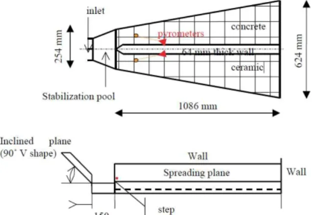
2.1 (VULCANO VE-U7) 이 연구에서 대상으로 적용한 노심 용융물의 거동 관련 실험은 EU의 ECOSTAR 프로젝트에서 이루어진 VULCANO VE-U7이다.(3) 플라즈마로 가열하여 만든 고온(2450K)의 용융물 40.8 kg을
과 같은 길이의 채널 형태 구조물 위
Fig. 1 1 m
로 총 4.3 kg/s의 유량으로 공급하고 시간에 따른 용융물 전단(front)의 위치를 측정한 것이다 채널. 은 바닥면이 각각 콘크리트와 세라믹으로 나누어 져 희생물질의 영향을 비교하였다.
전산유동해석 2.2
해석 모델 및 물성치 구성 2.2.1
위 실험 내용을 대상으로 상용 CFD코드인 을 이용하여 해석하였다
FLUENT v6.3 .(8) 이 때 작 동 유체는 액체 용융물 과 기체 공기 로 자유표면( ) ( ) 이 형성되는 이상유동(two phase flow)이 된다 따.
라서 여기에 적절한, Volume-of-fluid(VOF) 모델을 적용하고 Geo-construct 기법을 통해 자유표면을 추적하였다 그리고 고온 용융물로 인해 기체의.
대류 현상이 일어나므로 난류 계산을 위해
모델을 적용하였다 고온의 용융물에 standard k-ε .
의한 복사열전달은 구분종좌법(Discrete ordinate 를 적용하였다 이 때 용융물의 흡수계수
method) .
는 임의적이지만 10000 m-1로 설정하여 용융물 내부가 아닌 표면에서 주변과의 복사열교환이 이 루어지도록 하였다.
용융물의 주요 물성치는 Table 1과 같다 이 중. 점성은 퍼짐 해석에 가장 중요한 조건이나 기존, 의 예측모델 별로 용융물의 조성이나 온도에 따 라 크게 다르게 나타난다 이 연구에서는 입구온. 도인 2450K이하의 온도에 대해 기존 모델의 예 측 범위 내에서 Fig. 2와 같은 형태로 가정하여 적용하였다 바닥면의 열전도 계수는 희생물질의. 용융과 반응을 고려할 때 ~500kw/m2의 열유속(3) 에 해당하므로 희생물질의 두께, (0.2m)와 온도차
를 고려하여
(2450K- 323K) 50 W/m K로 설정하 였다.
해석 방법 2.2.2
은 해석에 쓰인 형상으로 의 중앙
Fig. 3 , Fig. 1
벽을 중심으로 대칭 형태로서 80,910개의 육면체 셀로 격자를 구성하였다 용융물의 입구는 실험. 결과에서 정확히 제시되지 않았으나 4 cm 높이 로 보았고 입구 온도는, 2450K이다 이 때 실험. 시의 유량이 2.15 kg/s이므로 속도는 0.0627m/s가 된다 입구의 온도. 2450K는 실제 실험에서 얻어 진 용융물의 액상 온도(liquidus temperature)와 고
Fig. 1 The VULCANO VE-U7 test geometry(2)
Density 7140 kg/m
3Specific heat 750 J/kg K Thermal conductivity 3 W/m K Viscosity Shown in Fig. 2
Emissivity 0.8
Absorption coefficient 10000 m
-1Surface tension 0.5 Contact angle 50°
Table 1 Properties of corium used in the simulation
Thermal conductivity 50 W/m K
Emissivity 0.8
Wall thickness 0.2 m Outerwall Temperature 323 K
Table 2 Heat transfer condition at the bottom wall
temperature (K)
1600 1800 2000 2200 2400 2600 2800 3000
v is c o s it y ( P a s )
10
-410
-310
-210
-110
010
110
210
310
410
510
6Stedman Arrhenius, C = 6 Residual liquid visosity This study
Fig. 2 Viscosity of corium in different prediction models and the model used in this study
Corium inlet (h=0.04m)
Gas outlet Side view
Top view
Fig. 3 Geometry of the channel in the simulation
상 온도(solidus temperature)로부터 용융물의 고체, 액체간의 부피비을 계산하여 이에 해당하는 값이 인 지점의 온도이다 계산 시 대류에 의한 가
50% .
스 유동이 해석의 안정성에 영향을 주지 않도록 위쪽 벽은 단열조건으로 하였고 가스의 출구는 채널 후단에 위치한다 상부 벽면은 온도. 323K, 방사율 1로 설정하여 주위로의 복사열손실을 모 사하였다 계산 시간 간격은. 0.001초로 용융물이 공급된 총 10초 동안 진행하였다.
결과 및 토의 3.
용융물 퍼짐 3.1
는 용융물의 전단 위치를 시간에 따라 Fig. 4
나타낸 것이다. 전체적으로는 시간이 지날수록 용융물의 퍼짐이 느려지는 경향은 같으나 용융물 공급이 끝난 t=10sec에서 전산해석 결과와 실험결 과의 차이가 약 0.12m 가량 나는 것을 확인할 수
있었다 이러한 결과는 물성치의 불확실성도 있. 으나 실험자료에서 입구 높이와 용융물의 유속이 명확히 측정되지 않아 발생한 것으로서 전산해석 방식 자체의 오차로 판단되지 않는다 이 결과를. 기초로 점성모델 복사열전달 등 용융물의 거동, 과 관련된 인자의 영향에 대한 세부적인 평가 연 구가 필요하다.
온도 및 점성 분포 3.2
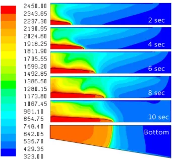
는 시간에 따른 용융물과 주변 공기의 온 Fig. 5
도 분포이다 용융물 전단의 온도는 시간이 지날. 수록 조금씩 낮아져 t=10sec일 때 2000~2100K까
Time (s)
0 5 10 15 20
C o ri u m f ro n t p o s it io n ( m )
0.0 0.1 0.2 0.3 0.4 0.5 0.6
VE-U7, ceramic substrate VE-U7, concrete substrate Numerical simulation
Fig. 4 Measured and predicted front position of corium
2 sec 4 sec 6 sec 8 sec
10 sec Bottom
Fig. 5 Temperature distribution (K) at the cross-section (t=2, 4, 6, 8 and 10 sec) and at the bottom wall (t=10 sec)
지 하락하였다 용융물 전단에서 수직 방향의 분. 포에서는 중앙부의 온도가 높고 상부와 하부로 갈수록 온도가 낮아지므로, 주로 바닥면으로의 전도와 벽면으로의 복사열손실에 의한 것이고 가 스로의 대류열손실에 따른 영향은 미미하였다.
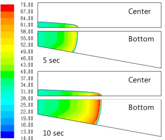
용융물 전단에서의 온도 하락은 점성의 변화에 직접적으로 영향을 주게 된다. Fig. 6은 5초와 10 초에서의 점성 분포를 나타낸 것으로 용융물 전 단에서 최대 70 kg/m s․이며 시간이 지날수록 낮아 지는 온도에 맞추어 점성 또한 증가하여 용융물 의 퍼짐을 느리게 만든다.
열손실 분석 3.3
은 상부 벽면으로의 복사열손실량과 바닥 Fig. 7
면으로의 전도열손실을 용융물 단면적으로 나누 어 열유속을 비교한 것이다 바닥면으로의 전도. 열손실은 실험치로부터 설정된 열전도도에 의해 결정된 값(~500 kW/m2)으로서 전단면의 온도 하 락에 따른 영향이 미미하다 그러나 복사열유속. 의 경우 온도의 4승에 비례하므로 그 영향이 시 간에 따라 확연히 나타나 초기에 1.6 MW/m2에서 t=10sec일 때 1.4 MW/m2 수준까지 감소하게 된 다.
4. 결 론
노외 노심 용융물의 거동 및 냉각과정은 점성 을 비롯한 물성치가 온도에 따라 급격히 변하므 로 적절한 열전달 해석 모델과 결합된 이상유동 의 신뢰성 있는 해석이 필수적이다 이 연구에서. 는 상용코드를 이용하여 3차원 형상에서의 복사 열전달을 포함한 비정상상태의 거동에 대한 해석 을 진행한 결과 용융물 내부의 온도분포와 이에 따른 점성변화의 예측 용융물의 퍼짐 현상의 복, 합적인 고려가 가능함을 확인하였다 향후 이 모. 델을 기초로 한 세부적인 물성치 변화의 영향을 평가하고, 코어캐쳐의 설계에 적용하는 과정이 필요하다.
후 기
본 연구는 지식경제부의 2009년 원자력기술개 발 사업 과제번호( :1415101207)의 지원으로 수행되 었으며 이에 감사드립니다.
참고문헌
(1) Jeong, H. W., Kim, D. H., Lee, K.-J., Kim, S.
B., Park, R. J. and Kim, H. D., 2000, “Simulated Experiments on High Pressure Melt Ejection in the Reactor Cavity during Severe Accident,” Trans. of the KSME(B), Vol. 24, No. 11, pp. 1447~1456.
(2) Ha, K. S., Kim J. T. and Kim, H. W., 2009,
"Concept and Evaluation Method of Ex-Vessel Core Catcher," KAERI/TR-3925/2009, Korea Atomic Energy Research Institute.
(3) Journeau, C., Haquet, J., Spindler, B., Spengler, C. and Foit, J., 2006, “The VULCANO VE-U7 Corium Spreading Benchmark,” Progress in Nuclear Energy, Vol. 48, No. 3, pp. 215~234.
5 sec
10 sec
Center
Center Bottom
Bottom
Fig. 6 Dynamic viscosity (kg/m s) of corium at the center and bottom (t=5 and 10 sec)
Time (sec)
0 1 2 3 4 5 6 7 8 9 10 11
H e a t fl u x ( M W /m
2)
0.0 0.2 0.4 0.6 0.8 1.0 1.2 1.4 1.6 1.8
Through the top wall
Through the bottom wall
Fig. 7 Heat loss per corium cross-sectional area through the top wall by radiation and through the bottom wall by conduction
(4) Cognet, G., Alsmeyer, H., Tromm, W.. Magallon, D., Wittmaack, R., Sehgal, B. R., Widmamm, W., De Cecco, L., Ocelli, R., Azarian, G., Pineau, D., Spindler, B., Fieg, G., Werle, H., Journeau, C., Cranga, M. and Laffont, G., 2001, “Corium Spreading and Coolability CSC Project,” Nuclear Engineering and Design, Vol. 209(1-3), pp. 127~138.
(5) Foit, J. J., 2004, “Spreading Under Variable Viscosity and Time-Dependent Boundary Conditions:
Estimate of Viscosity from Spreading Experiments,”
Nuclear Engineering and Design, Vol. 227, No. 2, pp. 239~253.
(6) Martin, R. P., Duncan-Whiteman, P. W. and Williams, E. S., 2009, “Core Melt Stabilization System Evaluation for the U.S. EPR™,” The 13th International Topical Meeting on Nuclear Reactor Thermal Hydraulics.
(7) Dinh, T. N., Konovalikhin, M. J. and Sehgal, B. R., 2000, “Core Melt Spreading on a Reactor Containment Floor,” Progress in Nuclear Energy, Vol. 36, No. 4, pp. 405~468.
(8) Fluent Inc., 2006, “Fluent 6.3 User’s Guide”.
Lebanon, New Hampshire, USA, 2006.