Vol.18, No.1, (2016), pp.59~63 http://dx.doi.org/10.9714/psac.2016.18.1.059
```
1. INTRODUCTION
The different cryogenic cooling systems have been applied to superconducting NMR magnets [1-3]. The typical cooling method in NMR magnets is to immerse magnets into liquid cryogen such as liquid helium. The NMR magnets composed of low temperature superconductor (NbTi, Nb3Sn) have used the cooling method that the magnet is immersed into liquid helium (4.2 K) or superfluid helium (under 2 K). The cooling method using liquid cryogen, however, is inconvenient due to the management of liquid cryogen during initial cool-down and normal operation. Recently, the high temperature superconductor is considered for NMR magnets [3-5]. The high temperature superconductor (HTS) has higher critical temperature and larger critical current density at high magnetic field than the low temperature superconductor. It, therefore, is expected as materials for the insert magnet of a high resolution NMR magnet (> 1 GHz). In addition, the high operating temperature of HTS magnets facilitates the cryogen-free cooling system by cryocoolers. The cooling mechanism of magnets is heat conduction in the cryogen-free cooling system by cryocoolers while it is heat convection of liquid cryogen in cryogen cooling system.
The conduction cooling system using cryocoolers makes the cooling system more flexible, user-friendly and compact than the cryogen cooling system. The user only needs to turn on the cryocooler for cool-down of magnets without the transfer and the filling of liquid cryogen.
The 400 MHz NMR spectrometer using a cryogen-free cooling system and a HTS magnet is being developed with
these advantages. The NMR magnet and the cooling system were designed by preliminary studies. This paper describes the verification of the thermal design of the cooling system for the NMR magnet, focusing on the magnet assembly. The thermal contact resistance is critical in the cryogen-free cooling system by thermal conduction.
The thermal analyses for conduction cooled HTS coils have been performed in previous studies [6-8]. The thermal analysis considering the thermal contact resistance, especially in contacts among HTS tapes of a HTS coil unlike previous studies, is performed in this paper. The structural stability of the thermal design is also checked from the structural analysis reflecting electromagnetic force and thermal contraction. The commercial software, COMSOL Multiphysics, is used for the analysis.
2. CRYOGEN-FREE COOLING SYSTEM
The schematic diagram of the cryogen-free cooling system and the heat flow by thermal conduction from the NMR magnet are shown in Fig. 1. The two stage pulse tube cryocooler that has no moving part at expansion space is used to minimize the vibration effect. The NMR magnet is thermally insulated by a vacuum chamber. The thermal shield thermally connected to the 1st stage of the cryocooler by thermal straps intercepts heat inflow from room temperature. The most of heat inflow results from Joule heating and heat conduction at current leads. The multi-layer insulation is also applied between the thermal shield and the vacuum chamber to reduce the thermal radiation. The NMR magnet is thermally linked to the 2nd stage of the cryocooler by the conduction cooling bar and
Thermal and structural analysis of a cryogenic conduction cooling system for a HTS NMR magnet
Sehwan In*, Yong-Ju Hong, Hankil Yeom, Junseok Ko, Hyobong Kim, and Seong-Je Park Korea Institute of Machinery and Materials, Daejeon, Korea
(Received 1 February 2016; revised or reviewed 29 February 2016; accepted 1 March 2016) Abstract
The superconducting NMR magnets have used cryogen such as liquid helium for their cooling. The conduction cooling method using cryocoolers, however, makes the cryogenic cooling system for NMR magnets more compact and user-friendly than the cryogen cooling method. This paper describes the thermal and structural analysis of a cryogenic conduction cooling system for a 400 MHz HTS NMR magnet, focusing on the magnet assembly. The highly thermo-conductive cooling plates between HTS double pancake coils are used to transfer the heat generated in coils, namely Joule heating at lap splice joints, to thermal link blocks and finally the cryocooler. The conduction cooling structure of the HTS magnet assembly preliminarily designed is verified by thermal and structural analysis. The orthotropic thermal properties of the HTS coil, thermal contact resistance and radiation heat load are considered in the thermal analysis. The thermal analysis confirms the uniform temperature distribution for the present thermal design of the NMR magnet within 0.2 K. The mechanical stress and the displacement by the electromagnetic force and the thermal contraction are checked to verify structural stability. The structural analysis indicates that the mechanical stress on each component of the magnet is less than its material yield strength and the displacement is acceptable in comparison with the magnet dimension.
Keywords : Conduction cooling, HTS, NMR magnet, Structural analysis, Thermal analysis
* Corresponding author: [email protected]
thermal straps. The heat generated by the magnet is eliminated to the 2nd stage of the cryocooler by thermal conduction. The NMR magnet is composed of 56 HTS double pancake coils generating 9.4 T at the center with operating current of 182.3 A. The magnet adopts no insulation, multi-width and notched structure. Its operating temperature is 20 K. The details of the magnet
are shown in Table I. Each double pancake coil has the cooling structure by which the heat generated in the coil is transferred to the conduction cooling bar and finally the cryocooler. Fig. 2 shows the details of a double pancake coil. The double pancake coil consists of two HTS single pancake coils, two legs, two wings, two thermal link blocks and a spacer. The wings and the thermal link blocks are made of highly thermo-conductive aluminum alloy (AL6061-T6) and copper, respectively. The thickness of the wing is 0.6 mm and that of the thermal link block depends on the distance between wings. The wing is also coated on each side by Teflon of 50 μm thickness for electrical insulation. The dimensions of the wing and the thermal link block are determined by preliminary simple thermal analysis. The heat generation or the sensible heat in a NMR magnet is eliminated by thermal conduction through wings and thermal link blocks connected to the conduction cooling bar. In addition, the G-10 plate of 0.2 mm thickness is used for the electrical insulation between singe pancake coils
3. THERMAL AND STRUCTURAL ANALYSIS
3.1 Thermal analysis
The thermal analysis is performed for the double pancake coil located in the magnet center. It is thermally farthest from the cold head of the cryocooler. The thermal properties used in the analysis are based on MPDB (Material Property Database, v7.99, JAHM Software). The orthotropic thermal conductivity in the HTS coil is determined by the rule of mixtures [9]. The thermal contact resistance is a critical factor in the case of dominant thermal conduction problem. The thermal contact resistance mainly depends on mechanical properties (Young’s modulus, hardness and surface roughness), thermal conductivity and contact pressure. If the contact materials are fixed, the thermal contact resistance is expressed as the function of contact pressure and surface roughness. Unfortunately, the experimental data for thermal contact resistance are not enough at cryogenic temperature. Fig. 3 indicates the thermal contact resistance in copper/copper contacts [10-12].
Fig. 1. Cryogen-free cooling system for a 400 MHz HTS NMR magnet.
2 stage pulse tube cryocooler
Thermal shield (aluminum alloy) Thermal straps (copper)
NMR magnet
Conduction cooling bar (copper) 1ststage of cryocooler
2ndstage of cryocooler
Vacuum chamber
Thermal link block Spacer
Heat flow
Wing Leg
Fig. 2. HTS double pancake coil with a conduction cooling structure.
TABLEI
DETAILS OF A 9.4THTSNMR MAGNET.
SPECIFICATION Value
# of double pancake coils 56 EA Central magnetic flux density 9.4 T
Operating current 182.3 A
Inner diameter 100 mm
Outer diameter 147 mm
Height 584 mm
Fig. 3. Thermal contact resistance in copper/copper contacts with respect to temperature and contact pressure.
The thermal contact resistance is changed with respect to temperature in Fig. 3, because mechanical properties of copper depend on temperature. In a HTS coil, copper/copper contacts exist among copper stabilized HTS conductors in radial direction. The contact pressure between conductors has the magnitude order of MPa, which is obtained by the structural analysis. In the thermal analysis, the experimental data for contact pressure of 1 kPa are conservatively used for radial contacts of HTS conductors. The thermal conductivity of a HTS coil in radial direction, therefore, is determined as follows.
1 2 c 1
s s i
c i i s
r R
k t t w R w
k t t w
w
k w (1)
where w, ws and t are the width of a HTS conductor, the width of copper stabilizer of a HTS conductor and the thickness of a HTS conductor, respectively, and ks, ti, ki and Rc indicates thermal conductivity of copper stabilizer, (i)th layer thickness of a HTS conductor, (i)th layer thermal conductivity of a HTS conductor and radial thermal contact resistance between HTS conductors, respectively. In addition, the thermal contact resistance for
copper/Teflon contacts at 4.2 K and contact pressure of 2.8 MPa from [9] is conservatively used for contacts among the wing, the thermal link block and the HTS coil where their temperatures are much higher than 4.2 K. The thermal radiation from the thermal shield to the HTS double pancake coil is also considered in the thermal analysis. The temperature of the thermal shield is assumed to be60K and the approximate material emissivity for each component of the HTS coil is used in the calculation of thermal radiation.
The Joule heating at the HTS coil takes place at lap splice joints. One double pancake coil has three lap splice joints with 100 mm joint length where HTS conductors are soldered to each other. Their electrical resistances range from 50 nΩ to 100 nΩ according to the location.
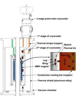
Fig. 4. Temperature distribution on the HTS magnet surface (unit : K).
Fig. 5. Overall temperature distribution in the HTS double pancake coil (unit : K).
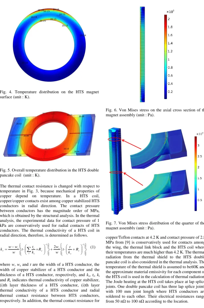
Fig. 6. Von Mises stress on the axial cross section of the magnet assembly (unit : Pa).
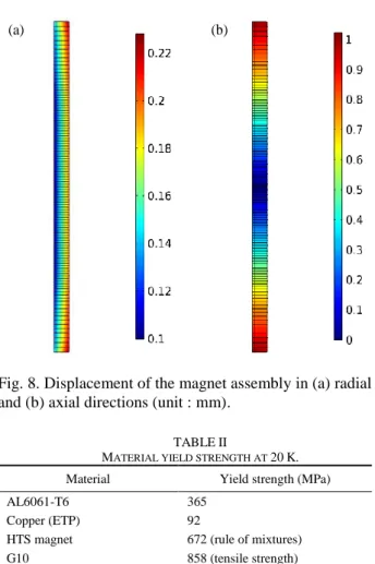
Fig. 7. Von Mises stress distribution of the quarter of the magnet assembly (unit : Pa).
The results from the thermal analysis are indicated in Fig. 4 and Fig. 5. Fig. 4 shows the temperature distribution of the magnet surface adjacent to the spacer when the sides of the thermal link blocks in contact with the conduction cooling bar are cooled at 20 K. The lap splice joints are biased toward one side as the worst case. The outside joint even does not come into contact with the cooling wing, which is for the work of soldering and connecting HTS conductors between double pancake coils. The heat generated in lap splice joints is diffused mainly in azimuthal direction and transferred to the cooling wing.
The high thermal conductivity of the HTS coil in azimuthal and axial directions and low thermal conductivity in radial direction make this thermal path. The thermal conductivity of the HTS coil in azimuthal and axial directions is more than 150 W/(m·K) while the thermal conductivity in radial direction is less than 2 W/(m·K) due to the thermal contact resistance. The heat generated at the outside joint, therefore, can be efficiently eliminated in azimuthal and axial direction though the joint is not in touch with the cooling wing. Fig. 5 indicates the overall temperature distribution of the HTS double pancake coil. Fig. 4 and Fig.
5 confirm that the uniform temperature distribution of the HTS double pancake coil is developed on present design basis within 0.2 K.
3.2 Structural analysis
The cooling structure design for the HTS magnet assembly determined from the thermal analysis needs to be
verified in terms of the structural stability. The HTS magnet assembly experiences the electromagnetic force and the thermal contraction. The mechanical stress on the HTS magnet components should not exceed their material yield strength. For the purpose, the structural analysis of the HTS magnet assembly is performed. In addition, the displacement of the magnet assembly by mechanical stress is checked. The mechanical properties for the analysis are based on MPDB (Material Property Database) like in the thermal analysis. The orthotropic mechanical properties of the HTS coil are also considered by the rule of mixtures [13].
Fig. 6 shows the von Mises stress on the axial cross section of the magnet assembly by the electromagnetic force and the thermal contraction. The stress gets higher at the center of the magnet assembly. Fig. 7 indicates the von Mises stress distribution of the quarter of the magnet assembly. The stress concentrations occur along the boundary between the wing and the HTS coil. The maximum stress, however, does not exceed 350 MPa.
Table II shows the yield strength of materials at 20 K, namely operating temperature, used in the HTS magnet assembly. The results of the structural analysis show that each component of the magnet assembly has the mechanical stress less than its material yield strength. The displacement of the magnet assembly is shown in Fig. 8.
The magnet assembly overall shrinks by thermal contraction while the electromagnetic force acts on the magnet radially outward direction and axially compressive direction. The maximum radial displacement is about 0.23 mm and the maximum axial displacement is about 1 mm in Fig. 8. The displacements are sufficiently small in comparison with the radial and axial magnet dimensions.
4. CONCLUSION
The conduction-cooled structure for the 400 MHz HTS NMR magnet preliminarily designed is verified by thermal and structural analysis. The thermal analysis considers orthotropic thermal properties of the HTS magnet, thermal contact resistance and radiation heat load. The uniform temperature in the present thermal design of the HTS magnet is developed within 0.2 K. The heat generated in the HTS magnet is efficiently eliminated by highly thermo-conductive wings and thermal link blocks thermally linked to the cryocooler. The structural analysis is performed to check the structural stability of the present magnet assembly design. The mechanical stress by the electromagnetic force and the thermal contraction on each magnet component is less than its material yield strength.
In addition, the displacements by the mechanical stress are within 0.23 mm in radial direction and 1 mm in axial direction, which is acceptable in comparison with the magnet dimension. The conduction-cooled NMR magnet is expected to make the NMR magnet system compact and user-friendly. The cooling structure design suggested in this study will be applied to the development of a cryogen-free 400 MHz NMR spectrometer.
Fig. 8. Displacement of the magnet assembly in (a) radial and (b) axial directions (unit : mm).
(a) (b)
TABLEII
MATERIAL YIELD STRENGTH AT 20K.
Material Yield strength (MPa)
AL6061-T6 365
Copper (ETP) 92
HTS magnet 672 (rule of mixtures)
G10 858 (tensile strength)
ACKNOWLEDGMENT
This work was supported by the Korea Institute of Machinery & Materials (KIMM), the Ministry of Science, ICT & Future Planning (MSIP), and KBSI grant (D36611) to S.-G.L funded by the Korea Basic Science Institute (KBSI).
REFERENCES
[1] H. Nagai et al., “Development and testing of superfluid-cooled 900 MHz NMR magnet,” Cryogenics, vol. 41, pp. 623-630, 2001.
[2] Y. Iwasa, J. Bascuňán, S. Hahn and D. K. Park, “Solid-cryogen cooling technique for superconducting magnets of NMR and MRI,”
Phys. Procedia, vol. 36, pp. 1348-1353, 2012.
[3] M. Mallett, D. Pooke and T. Husheer, “Cryogen-free, high resolution NMR magnets using high temperature superconductors,”
2014 Appl. Supercond. Conf., p. 95, 2014.
[4] J. Bascuňán, W. Kim, S. Hahn, E. S. Bobrov, H. Lee and Y. Iwasa,
“An LTS/HTS NMR magnet operated in the range 600-700 MHz,”
IEEE Trans. Appl. Supercond., vol. 17, no. 2, pp. 1446-1449, Jun.
2007.
[5] S. Hahn, D. K. Park, J. Voccio, J. Bascuňán and Y. Iwasa,
“No-insulation (NI) HTS inserts for > 1 GHz LTS/HTS magnets,”
IEEE Trans. Appl. Supercond., vol. 22, no. 3, Art. ID. 4302405, Jun.
2012.
[6] M. Song, Y. Tang, J. Li, Y. Zhou, L. Chen and L. Ren, “Thermal analysis of HTS air-core transformer used in voltage compensation type active SFCL,” Physica C, vol. 470, pp. 1657-1661, 2010.
[7] Y. Nagasaki, T. Nakamura, I. Funaki, Y. Ashida and H. Yamakawa,
“Coupled-analysis of current transport performance and thermal behavior of conduction-cooled Bi-2223/Ag double-pancake coil for magnetic sail spacecraft,” Physica C, vol. 492, pp. 96-102, 2013.
[8] J. Pelegrín et al., “Experimental and numerical analysis of quench propagation on MgB2 tapes and pancake coils,” Supercond. Sci.
Technol., vol. 26, Art. ID. 045002, 2013.
[9] M. D. Sumption et al., “Thermal diffusion and quench propagation in YBCO pancake coils wound with ZnO and Mylar Insulations,”
Supercond. Sci. Technol., vol. 23, Art. ID. 075004, 2010.
[10] E. Gmelin, M. Asen-Palmer, M. Reuther and R. Villar, “Thermal boundary resistance of mechanical contacts between solids at sub-ambient temperatures,” J. Phys. D: Appl. Phys., vol. 32, pp.
R19-R43, 1999.
[11] J. Yu, A. L. Yee and R. E. Schwall, “Thermal conductance of Cu/Cu and Cu/Si interfaces from 85 K to 300 K,” Cryogenics, vol. 32, no. 7, pp. 610-615, 1992.
[12] M. S. Kim and Y. S. Choi, “Measurement of thermal contact resistance at Cu-Cu interface,” Prog. Supercond.and Cryo., vol. 14, no. 4, pp. 1-5, 2012.
[13] A. K. Kaw, Mechanics of Composite Materials, CRC Press, New York, 1997.