1. INTRODUCTION
Fiberglass reinforced wood-based composite (FRWC) are functional materials that can be used for research on medical devices to support the body’s orthopedic rehabilitation (Guo, 2006;
Shen et al., 2006). As a substitute for the hu- man body, wood fiberboard has good breath- ability and the timber itself has a good human skin consistency, but its strength has not yet been proven to meet the requirements to support
the human body for a long time. With the ad- vantages of high strength, light weight, shock resistance, fatigue resistance, and corrosion re- sistance, FRWC also have good toughness, noise reduction performance, and low price (Ma, 1995; Biot, 1996). Wood fiberboard joined with fiberglass not only improves the performance of the composite material, but also broadens the scope of the application of fiberglass, especially in the field of medical device research, which will have a far-reaching significance (Lu et al.,
Original Article
Study on The Preparation and Mechanical Properties of Fiberglass Reinforced Wood-Based Composite
1Yang Zhang2,†⋅Yan Ma2
ABSTRACT
To study mechanical properties of fiberglass reinforced wood-based composite (FRWC), fiberglass with a di- ameter of 20 µm was selected to prepare test specimens. Mechanical properties of fiberglass reinforced wood-based composite were determined by three-point-bending test while its microstructure was characterizes by scanning electron microscopy (SEM). The results showed that mechanical properties of fiberglass reinforced wood-based composite were superior to that of the wood fiberboard based on the contrasting mechanical curves and the analysis of fracture mechanism. It is believed that the material design with this “sandwich” structure brings a unique buffering capacity of fiberglass into play in the composites. So the specimen did not produce a sudden fracture failure at high level of applied loads because it had a bearing ability. The SEM analysis showed that the working strength of PVAc adhesive was high; under a bearing force, it could properly transfer a load. In addition, glass fiber mesh and wood fiber board combined well.
Keywords : fiberglass, composite materials, wood fiberboard, mechanical properties
1 Date Received February 26, 2016, Date Accepted April 23, 2016
2 Forestry and Woodworking Machinery Engineering Centre, Northeast Forestry University, Mailbox 310, 26 Hexing Rd., Harbin 150040, P.R. China
† Corresponding author: Yang Zhang (e-mail: [email protected])
1996; Christensen et al., 1972; Bashar et al., 2013; Denneulin et al., 2012).
2. MATERIALS and METHODS 2.1. Materials
Wood fiberboard and fiberglass mesh were compounded to prepare FRWC. The composite material was a sandwich structure that had two layers of fiberglass net sandwiched between three wooden fiberboard structures, made in Weifang Juxin of China fiber products co.
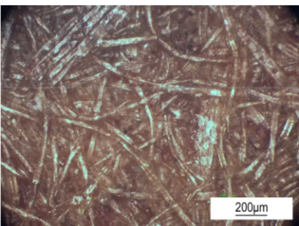
LTD, the mesh spacing of the glass fibers in the composite was 8 × 8 (mm), thickness was 2-5 mm, glass fibres net of density was 300 g/m2, and the diameter of a single glass fiber size was 13 µm, thickness of single-layer glass fibres is 1 mm. To eliminate impurities on the surface of the fiberglass, the fiberglass mesh was placed into 500 mℓ of ethanol (70%) be- fore the preparation and its surface were cleaned by ultrasonication, the model used was XTA-1025S, made in China, with 28 KHz fre- quency and 600 W power, which ensured that the adhesive and fiberglass had a good interface bonding during the subsequent preparation (Jain et al., 1992; Norman et al., 2003). The wood fiberboard in the composite material was mixed and pressed using 18 µm-diameter wood fibers and adhesive, wherein the thickness of the wood fiberboard’s outer layer was 2 mm and the thickness of the wood fiberboard’s inter- mediate layer was 3 mm, Board density was 0.8 g/cm3. Fig. 1 is a microscopic metallo-
graphic photograph of the wood fiberboard’s surface. As can be seen, the wood fibers and adhesive were well combined, and there were no obvious interface defects. Type 14L960 pol- yvinyl acetate emulsion made by Beijing Dynea Chemical Industry Co., Ltd was selected as the adhesive because of its suitability of the adhe- sion of plywood and wood fiber materials with reasonable price and better economical efficiency. It has a PH value of 6.5-7, a vis- cosity of 1.6-2.3 pa.s, dry strength of 8-12 Mpa and wet strength of 5.7-7.2 Mpa. Polyvinyl ace- tate adhesive, of which the composition are synthesized by polyvinyl acetate (64%) and poval (29%) with water (7%) added, is used as the adhesive because it can cure at room tem- perature, cure fast, with higher adhesive strength. (Guo et al., 2006; Lee et al., 2013). It is usually used for bonding wood materials and employs water as a dispersing agent, so it is safe, non-toxic, and non-flammable, the adhe- sive is suitable for bonding plywood and wood fiber materials, and the price is reasonable and Fig. 1. The mirrored organization of wood fiberboard.
economy is good (Simonsen, 1996; Al-Salem et al., 2009). The fiberglass reinforced wood-based composite board is shown in Fig. 2.
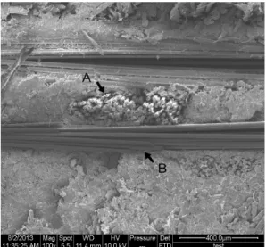
A scanning electron microscope (SEM) was used to observe the microstructure of the prepared FRWC, A place for glass fiber, glass fiber bundles can be seen from the point A closely packed, and fiberboard fuses in togeth- er, no separation phenomenon. B is fiberboard section morphology characteristics can be found after cold pressing the internal structure of fiberboard and destruction does not occur, sat- isfies the requirement of experiment, as shown in Fig. 3. The fiberglass and wood fiberboard were well connected under the effect of adhe- sive, and the interface of the composite materi- al had no obvious defects, which suggests that the preparation of composite materials was rea- sonable (Pedroso et al., 2005; Molgaard, 2005).
The three-point bending test on composite ma- terials is taken to test the mechanical properties of it.
2.2. Methods
According to European standard EN310-1989, EN3191995, as well as the national standard GB/T17657-1999, take specimen mading and testing, in the SANS - CMT5504 universal me- chanical testing machine, using three point bending method to determine the material’s elastic modulus and static bending strength.
Type MW-4 mechanical testing machine for wood is used to test the impact toughness of the specimen.
The composite material of sandwich structure manufacturing process is as follows: the fiber- board sizing amount is 10% of the weight of the fiberboard, unilateral glue; Glass fibres us- ing soaking adhesive, dipping time is more than 10 minutes, to ensure full penetration of resin, glue amount is 150% of the weight of the glass fibres. Above all after sizing, materials must be Fig. 2. The fiberglass reinforced wood-based compo-
site materials panel.
Fig. 3. The internal structure of fiberglass reinforced wood-based composite.
procuring more than 50 minutes, dehydrating adhesive curing before preloading. FRWC were prepared as follows: glue was applied on the surface of a wood fiber board and it was cov- ered by glass fiber net; subsequently, a press was applied for cold pressing with an applied pressure of 10 MPa for 24 h.
The size of the bending test sample was 120 mm by 20 mm by 10 mm (length by width by height). After the bending test was completed, the mechanical curves were analyzed. EVO 18 Series SEM made by German Carl Zeiss Company was used to observe the micro- structure of FRWC with 5-1000000x times of magnification, 3.0 nm at 30 KV resolution and continuously adjustable accelerating voltage 0.2 KV-30 KV. The material surface was sput- ter-coated with gold. In addition, to conduct a mechanical comparison test, a piece of three-layer wood fiber board without glass fiber in the middle but with the same structure was prepared.
3. RESULTS and DISCUSSION 3.1. The bending mechanical properties
of materials and analysis
FRWC are often applied as bracing for the human body; therefore, operational comfort is necessary. To realize this comfort, a material must have both good strength and toughness.
To test the mechanical properties of composite materials, the three-point bending test was con- ducted on FRWC. The curve shown in Fig. 4 is
the bending stress-strain curves of the force-displacement. There were four different variations among force-displacement curves, which were divided into four sections from point 1 to point 4. The mechanical performance curve of the material during the preliminary strain period appears to apparently rise follow- ing curving (such as Section 1-3 in the figure), and the curve in the section shows the creepage of wood fiber board and compaction of partial glass fiber mesh during the contact of the indenter. Then, the mechanical curve begins to decline; it does not show a dramatic change, but gradually decreases (as shown in the 3-4 range). The composite material begins to dem- onstrate fracture failure in this section. The results of three-point bending indicate that the material had strong tenacity and material failure is not instantaneous, but occurs gradually, which coincides with the fracture type of material. A mathematical method was used to analyze the mechanical curves.
The slopes of the linear segments of Fig. 4 from point 1 to point 2 and point 2 to point 3 are different. The linear segment can be de- Fig. 4. Curve of force-displacement of sample.
scribed by the following equation:
kx
F = ··· (1) where F is the bending load (N), x is the vertical displacement of the specimen (mm), and kis slope of the line.
Modulus of elasticity, E (MOE), is a parame- ter that can be used to describe the effect of the deformation under the applied load, and it can be used to evaluate the buffer capacity. k and E demonstrate a positive relationship (Thomason, 1996).
E ∞ k ··· (2) According to the mixture law concerning the modulus of elasticity of composites (Hull et al., 1996), the total composite elastic modulus Etotal of composite can be described using Eq.4, where ti is the thickness of different parts of the composite (m); Vi is the volume of different parts of the composite (m3); Etotal is the total composite elastic modulus (MPa); V is the vol- ume (m3); and S is the cross-sectional area (m2), Because this material design is similar to the layer and plate structure, the area of the different components are the same.
T E t ST E St V E V
E i i i
n i i i
n i i i
n
total =Σ=1 / =Σ=1 / =Σ=1 / ·· (3)
In this experiment, the composite material is composed of two parts, namely the outer part and the intermediate layer that are fiberboard section and the fiberglass mesh. Due to the for-
mula (3) and (4), the express k equation of two linear can be derived as:
T k t k i i i
n
total =Σ=1 / ··· (4) where ktotal is the slope of the total composite material, ti is the thickness of the composite parts of different composition (m), ki is he slope of the composite parts of different com- position, and T is the total thickness of the composite material (m).
The first length of the straight line was from point 1 to point 2, and the corresponding dis- placement of the specimen was 0.7 mm to 5.5 mm. At the moment that the three-part wood fi- ber and fiberglass shared the applied load,
2 1−
total
k can be obtained with Eq. 6,
c v
c c c v
v
total v t t
k t t t
k k t
+ +
= +
−
2 2
2
2 1
··· (5)
where
2 1−
total
k is the slope of a line segment from point 1 to point 2, kv is the elastic mod- ulus of the fiberboard, divided into three sec- tions (upper, middle, and lower), and kc is the modulus of elasticity of the fiberglass portions.
As the load continued to increase, the force and displacement curve reached point 2. At this time, the upper layer of the fiber board contact- ing the indenter was firstly destroyed because of the large load. Thereafter, as the applied load increased, the load was shared by the mid- dle layer, the lower layer, and the fiberglass network. The displacement of corresponding specimens was 5.5 mm to 13.2 mm, so the
slope ktotal2−3 of the straight line segment from point 2 to point 3 can be written as Eq. 7.
c v
c c c v
v
total v t t
k t t t
k k t
+ +
= +
−3 2
··· (6) By comparison of Eqs. 6 and 7,
3 2 2
1− −
> total total k
k . From Eq. 3, the slope k of the linear segment portion is proportional to the elastic modulus E of the material. Therefore, the following conclusion can be made:
3 2 2
1− −
> total
total E
E . Compared to wood fiberboard, the elastic modulus of the total composite material decreased. However, the area surrounded by the curve portion under force and displacement increases. Application of this “sandwich” struc- ture can effectively prevent the brittle fracture of the material (Peijs, 1998; Ma, 2002).
3.2. Mechanical properties comparison of test specimens
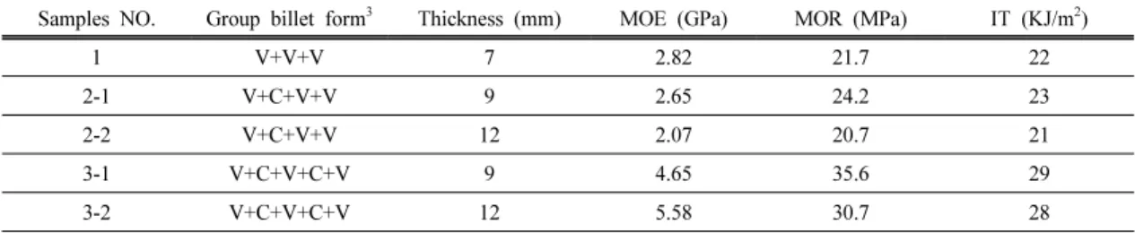
There are at least 5 samples under the same process used in the test, Table 1 shows the average of test results of all specimens.
The result of comparison of the mechanical properties of specimens in group No.1, 2 and 3
are shown in Table 1 and Fig. 5. For elasticity modulus, the value of specimens in group No.2 is the smallest of all specimens, smaller than wood fiber venner. After comparing the speci- mens, it confirms that when single-layer fiber glass is added, the density of glass fiber is too small and bad for the increase of elasticity modulus of material. And for specimens in group No.3, the adding-in of double-layer fiber glass mat is favorable for the increase of elas- ticity modulus of material.
The curves in Fig. 6a are the bending stress-strain curves of the FRWC. Following curving, when the strain reaches 4%, the max- imum bending stress of the material is 30 MPa.
The mechanical performance curve of the mate- rial shows slowly drop when the strain reaches
Samples NO. Group billet form3 Thickness (mm) MOE (GPa) MOR (MPa) IT (KJ/m2)
1 V+V+V 7 2.82 21.7 22
2-1 V+C+V+V 9 2.65 24.2 23
2-2 V+C+V+V 12 2.07 20.7 21
3-1 V+C+V+C+V 9 4.65 35.6 29
3-2 V+C+V+C+V 12 5.58 30.7 28
Note: aV = Wood fiberboard, C = Fiberglass net, MOE = Modulus of elasticity, MOR = Static bending Strength, IT = Impact toughness.
Table 1. Experimental design and mechanical properties of the specimens
0 1 2 3 4 5 6
1 2 3
MOE(GPr)
Specimen Groups Specimen 1
Specimen 2
Fig. 5. Comparisons of MOE.
4%-7%, also the bending stress of the material keep 25 MPa. Then, the mechanical curve be- gins a sudden drop, indicating that the material has lost effect slowly at this time. For compar- ison, the three-point bending mechanical test for wood fiberboard was also conducted. The curves in Fig. 6b are the bending stress-strain curves of wood fiberboard. Following curving, the mechanical performance curve of the mate- rial shows a noticeable upward trend in the ini- tial strain, but when the strain reaches 3%, the maximum bending stress of the material is 30 MPa. Then, the mechanical curve begins a sud- den drop, indicating that the material has lost effect at this time. By comparing the mechan-
ical curve of the two materials, it can be de- termined that the toughness of the FRWC was better than that of wood fiberboard (Evans et al., 1986; Ma, 2003). This illustrates that after adding fiberglass mesh, the mechanical proper- ties of the wood fiberboard were optimized, giving it good strength and toughness.
3.3. The fracture morphology and analysis The FRWC was observed after bending. As shown in Fig. 7, there was bending deformation in the middle of the specimen. Bending destruc- tion occurred in the outermost layer, as shown by arrow A. As shown by arrow B, the wood fiber board in the medium layer was destroyed, which occurs in the middle layer of wood fiber- board’s interior. Using SEM, the microstructure of arrow C can be observed, as shown in Fig.
8. Then, it can be found that a combination of interface between the wood fiberboard and fiber bundle was still good. Meanwhile, it was clearly observed that no delaminated destructive phenomenon occurred between the plate and the Fig. 7. The macroscopic damage morphology of fi- berglass reinforced wood-based composite materials.
(a)
(b)
Fig. 6. The bending stress-strain curves of wood fiberboard.
plate in Fig. 7, which indicates adhesive has a high potential to meet the strength requirements of the material when it is stressed. Test results show that the choice of adhesive is reasonable because it has high work intensity and can be a good load transfer when stressed.
4. CONCLUSION
(A) Using scanning electron microscopy (SEM) to observe the microstructure of fiberglass reinforced wood-based composite (FRWC), it is clear that no damage occurred between the plates. The adhesive infiltrates into the gaps and depressions on the surfaces of materials as liquid, mesh connection on the interface is formed after curing. This result means that polyvinyl acetate adhesive has a high work strength and can transmit a load well when it is pressed.
(B) Special forms of force and displacement curve under the three-point bending test of composite materials are revealed by changes in elastic coefficient, which indicates that under bending load, the energy absorption capacity of the material increases. Therefore, with large deformation, the material is not easy to damage.
At the same time, the structural characteristics of the glass fiber network make it able to withstand large force and destructive energy consumption after the destruction of the wood fiberboard’s outer layer. Therefore, the materials have good cushioning properties.
(C) From the bending stress-strain curve of the three-point bending test, mechanical proper- ties can be determined. Wood fiberboard in the beginning of the mechanical properties strain curve shows a clear upward trend. When the strain reaches 3%, the maximum bending stress of the material is 30 MPa. Then, the mechan- ical curve begins to suddenly drop, indicating that the material at this time has reached Fig. 8. The scanning photos of fiberglass reinforced
wood-based composite.
failure. The results show that the mechanical performances of wood fiberboard were opti- mized after glass fiber mesh was added.
ACKNOWLEDGEMENTS
The project was supported by the National Natural Science Found Project of China (grant no.
31170517) and the Natural Science Foundation Project of Hei longjiang province (grant no.
C201413).
REFERENCES
Al-Salem, S.M., Lettieri, P., Baeyens, J. 2009.
Recycling and recovery routes of plastic solid waste (PSW): a review. Waste Management (Oxford) 29(3): 2625∼2643.
Biot, M.A. 1996. Theory of propagation of elastic waves in a fluid-saturated porous solid. I. Low frequency range. Journal of the Acoustical Society of America 28(2): 168∼178.
Bashar, M.T., Sundararaj, U., Mertiny, P. 2013.
Mode-I interlaminar fracture behaviour of nano- particle modified epoxy/basalt fibre-reinforced laminates. Polymer Testing 32(2): 402∼412.
Christensen, R.M., Waals, F.M. 1972. Effective stiff- ness of randomly oriented fibre composites.
Journal of Composite Materials 6: 518∼532.
Denneulin, S., Viot, P., Leonardi, F., Lataillade, J.L.
2012. The influence of acrylate triblock co- polymer embedded in matrix on composite structures’ responses to lowvelocity impacts.
Composite Structures 94(5): 1471∼1481.
Evans, K.E., Gibson, A.G. 1986. Prediction of the maximum packing fraction achievable in ran- domly oriented short-fibre composites. Composite Science Technology 25(2): 149∼162.
Guo, M. 2006. MorPhology controlling and proper- ties of polyporpylenel/glass fiber composites obtainedvia shear sterss field. Ph.D. Thesis, Sichuang University, CHN.
Guo, M., Yang, H., Tan, H., Wang, C., Zhang, Q., Du, R. 2006. Shear enhanced fiber orientation and adhesion in PP/glass fiber composites.
Macromolecular Materials and Engineering 291(3): 239∼246.
Hull, D., Clyne, T.W. 1996. An introduction to com- posite material, 2nd Ed., Cambridge University Press, UK.
Jain, L.K., Wetherhold, R.C. 1992. Effect of fiber prientation on the fracture toughness of brittle matrix composites, Acta Metallurgica et Materialia 40(6): 1135∼1143.
Lee, C.F., Sue, H.J., Fiscus, D.M. 2013. Refined fixture design for effective essential work of fracture toughness characterization of m-LLDPE thin films. Polymer Testing 32(2): 256∼264.
Lu, G.H., Li, X.T. 1996. Electrical properties and shielding effects (by theoretical calculation) for larbon fibers/abs resin composites mixed by three different ways. Composites and Technology 12(56): 193∼199.
Ma, Y. 1995. The exploration on analytical method of micromechanics model and rigidity parame- ters of Scrimber. Journal of Northeast Forestry University 23(4): 107∼111.
Ma, Y. 2002. Study on quantitatively calculated theory of micro-meter wood fiber directional reconstituted content of cell fiber. Journal of Biomathematics 17(3): 353∼357.
Ma, Y. 2003. Study on cell break theory of using wood fiber micro-meter aligned reconstituted technology forming super High-intensity Wood-based Panel. Scientia Silvae Sinicae 39(3):
111∼115.
Molgaard, C. 2005. Environmental impacts by dis-
posal of plastic from municipal solid waste.
Resources Conservation and Recycling 15(2): 51
∼63.
Norman, D.A., Robertson, R.E. 2003. The effect of fiber orientation on the toughening of short fi- ber-reinforced polymers. Journal of Applied Polymer Science 90(10): 2740∼2751.
Pedroso, A.G., Rosa, D.S. 2005. Mechanical, thermal and morphological characterization of recycled LDPE/corn starch blends. Carbohydrate Polymers 59(5): 1∼9.
Peijs, T., Garkhail, S., Heijenrath, R., Vanden Oever, M., Bos, H. 1998. Thermoplastic composites based on flax fibre and polypropylene: Influence
of fibre length and fibre volume fraction on me- chanical properties. Macromolecular Symposia 127(3): 193∼203.
Shen, G. L., Hu, G.K. 2006. Compound material mechanics. Tsinghua university press, Beijing, CHN.
Simonsen, J. 1996. Utilizing straw as a filler in ther- moplastic building materials. Construction and Building Materials 10(1): 435∼440.
Thomason, J.L., Vlug, M.A. 1996. Influence of fibre length and concentration on the Properties of glass fibre-reinforced polypropylene: 1. Tensile and flexural modulus. Composites A 27(1): 477
∼484.