Effect of PWHT on Variability of fatigue Crack Propagation Resitance in TIG Welded Al 6013-T4 Aluminum Alloy TIG 용접된 Al6013-T4 알루미늄 합금에서 피로균열전파저항의
변동성에서의 PWHT의 영향
Gunawan Dwi Haryadi
1, Sang Yeul Lee
2, and Seon Jin Kim
3구나완 · 이상열 · 김선진
(received 01 july 2011, revised 08 August 2011, accepted 13 August 2011)
Key Words:Fatigue crack propagation (피로균열전파), Artificial aging time (인공시효시간), TIG (Tungsten inert gas welding) (용접), Reliability model (신뢰성 모델), Variability of fatigue crack propagation resistance (피로균열전파저항의 변동성)
Abstract:The experimental investigation focuses on an influence of artificial aging time in longitudinal butt welded Al 6013-T4 aluminum alloy on the fatigue crack growth resistance. The preferred welding processes for this alloy are frequently tungsten inert gas welding (TIG) process due to its comparatively easier applicability and better weldability than other gas metal arc welding. Fatigue crack growth tests were carried out on compact tension specimens (CT) in longitudinal butt TIG welded after T82 heat treatment was varied in three artificial aging times of 6 hours, 18 hours and 24 hours. Of the three artificial aging times, 24 hours of artificial aging time are offering better resistance against the growing fatigue cracks. The superior fatigue crack growth resistance preferred spatial variation of materials within each specimen in the Paris equation based on reliability theory and fatigue crack growth rate by crack length are found to be the reasons for superior fatigue resistance of 24 hours of artificial aging time was compared to other joints. The highest of crack propagation resistance occurs in artificial aging times of 24 hours due to the increase in grain size (fine grained microstructures).
김선진 (교신저자) : 부경대학교 기계자동자공학과 E-mail : [email protected],
구나완 : 부경대학교 대학원 이상열 : 포항대학
1. Introduction
Aluminum alloys are widely uses as aerospace materials and automotive materials related to fa- tigue damage. Aluminum alloys with the addition of alloys elements consisting of Mg and Si, and Mn, Cr, Ti, Cu can improve the mechanical strength and tensile strength. Al-Mg-Si of alu- minum 6000 series has the properties of light weight, high yield strength, workability, form- ability, and good corrosion resistance as aerospace and automotive body materials are widely recog-
nized
1).
In all cases, welding is the primary joining method and fatigue is a major design criterion.
However, as is well known, welded joints can exhibit low fatigue properties. Thus, clear design guidelines are needed to ensure that fatigue fail- ures are avoided in welded aluminum alloy structures. Apart from basic design of new struc- tures, there is also increasing interest in methods for assessing the remaining lives of existing structures
2).
Prompted by difficulties experienced in reaching
a consensus on fatigue design rule, extensive
testing and analysis of the fatigue performance of
welded aluminum alloy have been undertaken
over the past few years. Analysis and extensive
testing on fatigue properties of welded joints alu-
minum, many researchers have studied by the last decade
3).
TIG welding process is one of the most well established processes which can not only weld all metals of industrial use but produces the best quality welds amongst the arc welding processes, because of advantages such as lower prices, in particular, the easy and precise control of welding parameters. Unfortunately, a lot of hot cracking occurred in almost all of the heat treatment of aluminum alloys. The main problem in welding these alloys is welding cracking (solidification cracking) in the weld, and the heat treatment can be improved. At this time the aging time and temperature are important variables. Thus, by heat treatment after welding is very important to investigate the fatigue crack propagation behavior in terms of welded damage tolerance design
4).
Fatigue test are widely used to characterize the behaviour of materials, though they tend to be more used for sample testing of uniform material.
To determine the fatigue tendency of welded joint, the study and control of the tests is more complex, as welded joints present microstructural variations over small distance, not to mention complex distributions of residual stresses. A more detailed study of the fatigue behaviour of welded joints is necessary as it provides data for de- termining the resistance structures
5).
Failure analysis of the weldedment indicated that fatigue alone is to be considered to account for most of the disruptive failures. Even though the failure properties of the weld metal is good, problems can occur when there is an abrupt change in section which is caused by excess weld reinforcement, undercut, slag inclusion, and lack of penetration, and nearly 70 % of fatigue crack- ing occurs in the welded joint.
6).
The fatigue behaviour of an Al-Mg-Si alloy lap welded joints and the improvement in fatigue strength due to post weld heat treatment were investigated by Pinho da Cruz et al
7).
In this study reports the influence of post weld heat treatment (PWHT) on fatigue crack growth
resistance of TIG welded AL 6013-T4 aluminum alloy. Among them, artificial aging time is differ- ently performed to heat treatment on 6 hours, 18 hours, and 24 hours. Based on reliability theory, according to the crack length and the spatial var- iability of the material fatigue crack propagation rate comparisons were investigated.
2. Materials and Experiment Methods
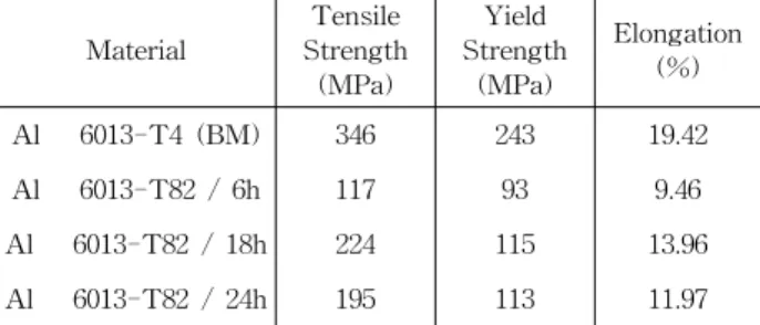
2.1 Material and Specimens, Welding condition Specimen materials used in this study, Al 6013-T4 aluminum alloy sheet as a test specimen length direction of the 500 × 250mm plate was carried out heat treatment-T82 after longitudinal TIG weld. Different treated artificial aging time, were carried out by 6 hours, 18 hours and 24 hours for CT specimens according to ASTM E647 standard fatigue tests. The shape and di- mension of CT specimen used in this study are shown in Fig. 1. The chemical composition and mechanical properties of Al 6013-T4 are shown in Table 1 and Table 2, respectively
8).
Table 1 Chemical composition (wt.%)
Material Mg Si Cu Mn Fe Cr Ti Zn 6013-T4 1.0 0.8 0.9 0.4 0.3 0.1 0.1 0.1
Table 2 Mechanical properties of base metal and post welding heat treatment specimens
Material
Tensile Strength
(MPa)
Yield Strength
(MPa)
Elongation (%)
Al 6013-T4 (BM) 346 243 19.42
Al 6013-T82 / 6h 117 93 9.46
Al 6013-T82 / 18h 224 115 13.96 Al 6013-T82 / 24h 195 113 11.97
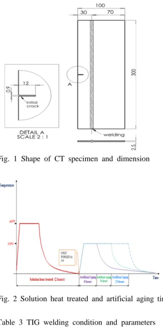
Fig. 2 shows for each the T82 solution treat-
ment and artificial aging time, respectively. The
welding conditions for TIG welding was carried
out the rolling direction using the Al 5356 filler
with 3.2mm diameter can be seen in Table 3.
Fig. 1 Shape of CT specimen and dimension
Fig. 2 Solution heat treated and artificial aging time
Table 3 TIG welding condition and parameters
Parameter values
Welding machine Miller
Tungsten electrode diameter 3.0 mm Filler rod/wire diameter 3.2 mm
Heat input 2.5 kJ/mm
Peak current 70 Amps
Base current 60 Amps
Peak voltage 15 Volts
Base voltage 10 Volts
Welding Speed 2.5 mm/sec
Welding grade 99.95%
Melting point 543
0C-640
0C
Pulse frequency 6 Hz
Pulse on time 50 %
Shielding gas argon
Gas flow rate 15 lit/min
2.2 Fatigue crack propagation experiments
The fatigue crack growth experiments were
conducted using a close loop servo-hydraulic fa- tigue testing machine (Shimadzu) at room temperature. All test were carried out in a sinus- oidal tension-tension under constant amplitude loading control mode for controlled loading range ( △ P) 980 N, the stress ratio (R) 0.3, and the fre- quency 5-11 Hz. Conditions that was observed for each treatment and artificial aging 3 per pre- scription, for a total of 12 specimens. The meas- urement of crack length was measured using a travelling microscope, the equation of ASTM E647 were used by the crack tip stress intensity factor. The initial crack length a = 15 mm to 54.5mm including from pre-crack intervals in 0.5mm cracks were treated by normalization.
3. Result and Discussion
3.1 Fatigue crack propagation behavior in artificial aging time
Fig. 3, three specimens and base metal parts to artificial aging treated by three each differently, a total of 12 specimens shows a relationship be- tween in the number of cycles N and crack length for the stress. As shown in this figure that fatigue crack growth are differently indicated by artificial aging time in such a post weld heat treatment of T82, fatigue crack propagation re- sistance is 24 hours of artificial aging time great- er than 6, 18 hours artificial aging time in order.
In case of base metal were indicated softly curve shape by stress-number of cycles in crack prop- agation, but other data of 3 types in such cases were indicated irregular results at nearby 30 mm of crack length.
However, there is a variation of the specimen
within the curve of the form is showing. On the
other hand, randomness of a-N curve for each 3
specimens by same condition was known less
than other structure steel materials. It is thought
that crack propagation is due to passed through
heat affected zone, weld fusion zone, and weld
metal on nearby 30 mm of crack length. It is
mean that specimen to specimen variation is low
and it is considered that the variation within each specimen is some existed for fatigue crack prop- agation rate.
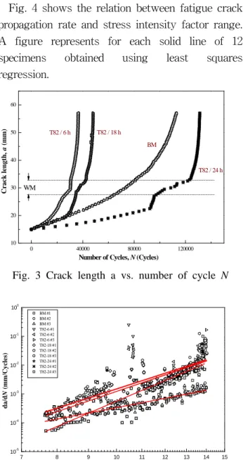
Fig. 4 shows the relation between fatigue crack propagation rate and stress intensity factor range.
A figure represents for each solid line of 12 specimens obtained using least squares regression.
0 40000 80000 120000
10 20 30 40 50 60
BM
T82 / 24 h T82 / 18 h
Number of Cycles, N (Cycles)
Crack length, a (mm) T82 / 6 h
WM
Fig. 3 Crack length a vs. number of cycle N
7 8 9 10 11 12 13 14 15
10-5 10-4 10-3 10-2 10-1 100
BM #1 BM #2 BM #3 T82-6 #1 T82-6 #2 T82-6 #3 T82-18 #1 T82-18 #2 T82-18 #3 T82-24 #1 T82-24 #2 T82-24 #3
da/dN (mm/Cycles)
ΔK
[
MPa m1/2]
Fig. 4 Relationship between fatigue crack propagation rate and stress intensity factor range (all specimens)
In the actual practice, the regression line will be interpreted that all data. That data mean the fatigue crack propagation on weld metal delay and then acceleration phenomenon. The regression line is not in the actual welding, on the actual welds to be included by adding a non-linear. In the following, using the data based on reliability theory, the volatility of fatigue crack propagation is investigated.
3.2 Analysis of based on fatigue crack propagation model
Based on fracture mechanics to assess the fa- tigue crack propagation behavior has many differ- ent expressions, but the most widely used was based on the following Paris equation.
∆
(1) Where da/dN is the fatigue crack propagation rate and △ K is stress intensity factor range (SIF), “C” and “m” are the material constants. To be random variable methods of fatigue crack propagation based on reliability theory can be largely split in three parts.
First is the specimen-to-specimen variation, second is the variation within each specimen, and third is specimen-to-specimen variation and the variation within each specimen at the same time.
In other words, the existing material constant C of the Paris-Erdogen equation is modeled as folllows.
(2) Where a represents position (crack length) in the crack tip, C
1is a positive random variable describing the deviation between the behavior of different specimens, C
2is random process model- ing the deviation of the crack propagation rate within each specimen
9).
∆
(3)
In this case, variation of crack propagation rep- resents within each specimen if C
1and m has fixed. Spatial variation of material is possible to treat the fatigue crack propagation model process.
The variation of C
2by crack length for each specimen of artificial aging times on base metal, 6 hours, 18 hours and 24 hours are shown in Fig.
5-8.
Appears on the picture, a results of inves-
tigation in variation of C
2by crack length were
represented that 24 hours specimens of artificial
aging time is the most greatest in its variation.
10 20 30 40 50 60 -8
-6 -4 -2 0 2 4 6 8
BM
C2
Crack length, a (mm)
Fig. 5 Variation of C
2base metal
10 20 30 40 50 60
-8 -6 -4 -2 0 2 4 6 8
C2
Crack length, a (mm) T82-6 hours
WM
Fig. 6 Variation of C
2PWHT T82-6 hours
10 20 30 40 50 60
-8 -6 -4 -2 0 2 4 6 8
C2
Crack length, a (mm) T82-18 hours
WM
Fig. 7 Variation of C2 PWHT T82-18 hours
10 20 30 40 50 60
-8 -6 -4 -2 0 2 4 6 8
Crack length, a (mm) C2
T82-24 hours
WM
Fig. 8 Variation of C2 PWHT T82-24 hours
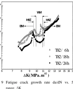
Meanwhile, the C
2of the fluctuations around the weld metal of artificial aging tendency to in- crease with time, crack growth delay means to improve effectiveness.
6 7 8 9 10 11 12 13 14 15 16 17