천리안 위성 Ka 대역 통신탑재체시스템 기술
이성팔, 조진호, 유문희, 최장섭, 안기범 정회원
Ka band Communication Payload System Technology of COMS
Seong Pal LEE, Jin Ho JO, Moon Hee YOU, Jang Sup CHOI, Ki Burm AHN Regular Members
요 약
통신해양기상위성은 4개 정부부처 공동사업으로, 통신서비스, 해양기상 관측서비스를 7년간 제공하게 된다. 위성 스위칭 중계기와 다중빔 안테나로 구성된 Ka 통신탑재체 개발은 방송통신위원회 출연으로 ETRI 주관으로 개발하였으며, 통신탑재체 개발목적은 우 주인증 기술확보와 차세대 멀티미디어 위성서비스 개발이다.
본 논문 목적은 통해기 통신탑재체 국산 개발사업의 전 과정을 통한, ETRI 의 Ka대역 통신탑재체 개발기술 연구이며, 또한 통신 탑재체 응용 기술에 대해 다루고자 한다.
Key Words : Ka Communication Payload, Geostationary satellite, switching transponder, multi-beam antenna.
ABSTRACT
COMS (Communication, Ocean and Meteorological Satellite) is the multi-purposed Korean geostationary satellite funded by four Korean government ministries, and is to supply communication services, ocean and weather observation for 7 years. As part of COMS, development of Ka band communication payload composed of microwave switching transponder and multi-horn antenna is sponsored by KCC (Korea Communications Commission) and developed by ETRI (Electronics and Telecommunications Research Institute). The purpose of Ka Payload development is to acquire space proven technology of Ka payload and to exploit advanced multimedia communication services.
This paper aims to study development technology of Ka payload system through whole process of ETRI project. Also application of Ka payload will be dealt in this paper.
한국전자통신연구원 위성무선융합연구부 ([email protected], [email protected], [email protected], [email protected]) 접수일자 : 2010년 9월 20일, 수정완료일자 : 2010년 10월 6일, 최종게재확정일자 : 2010년 10월 20일
I. Introduction
Chunrian satellite (COMS : Communication, Ocean and Meteorological Satellite) is the first geostationary satellite developed by local developers funded by four Korean government Ministries including Ministry of Education and Technology, Korea Communication Commission, Ministry of Land, Transport and maritime Affairs, and Korea Meteorological Agency, and will be used for multi-purposes such as communication services,
ocean and weather observation for 7 years . Ka band communication payload development, as a part of COMS project, is sponsored by Korea Communication Commission and developed by Electronics and Telecommunications Research Institute with local companies (SaTREC-I, KoSpace, M&M Lynx, Korean Air Line and ART).
The purpose of Ka Payload development is to acquire space proven technology of Ka equipment and system and to exploit advanced multimedia communication services. ETRI with domestic technologies successfully developed Ka payload equipments and system throughout
Parameters Features Service area Korean peninsula Relevant frequency
band
29.6~30.0GHz(uplink) 19.8~20.2GHz(downlink) Orbit and position Geostationary at 128.2°E
Service Life 7.7 years
design, manufacturing and test. ETRI completed IOT (In Orbit Test) of Ka Payload and verified the final status of the Payload located at GEO in 128.2 E. IOT test result of Ka Payload is compliant with specification and same as that of Thermal Vacuum Test done at ground test.
Ka Payload developed by ETRI will be applied for R&D experiment, Test-bed for new technology verification and Public services test. Domestic developed technology of Ka communication payload will be contributed to exploit new multi-media services.
Ⅱ. Ka Payload System Design
The payload system will provide high-speed multimedia services such as Internet via satellite, remote-medicine, and distance learning in the public communication network and communication services for natural disaster such as prediction, prevention, and recovery services in the government communications network. The main feature of the Ka-band communication payload is shown in Table 1.
Table 1: Main feature of the Ka-band payload system
The service coverage of the COMS Ka-band payload system is South Korea and North Korea via individual satellite beams for communication services.
The individual regions will be covered by separate single beam. The beam width of each beam has 0.7 degree including 0.1 degree pointing error.
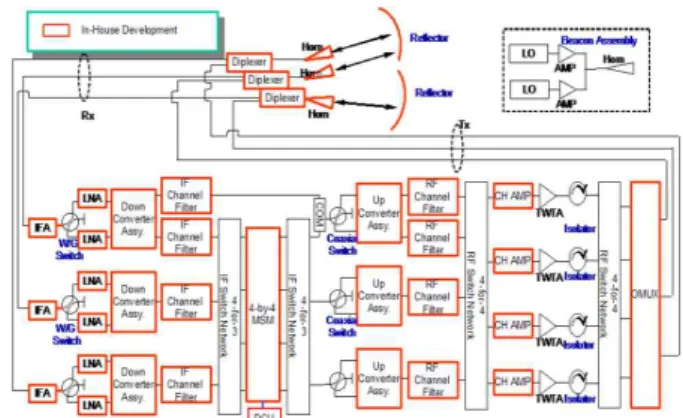
The payload architecture utilizes Ka-band on-board switching transponder and multi-beam antenna designs. The payload block diagram shown in Figure 1 illustrates that the Ka-band transponder provides four channels including one redundancy, two antennas and a beacon assembly.
Ka Payload performance in the final design phase is fully compliant with the required system specifications.
Figure 1: Ka-Band payload functional block diagram
Ⅲ. Ka Payload System Manufacturing, Integration and Test
1. Equipment and Transponder Manufacture
Around 80 % of all equipments of Ka Payload system were designed and manufactured by ETRI and local companies, and the other 20% were procured from oversea manufactured.
All the developed equipments were manufactured, in the phases of EM and EQM, tested and verified confirming space environment requirement. In the phase of FM, all equipments of Ka Payload met the requirement of space environment and interface supplied by COMS spacecraft from Astrium. The FM equipments were integrated into Transponder panel supplied by Astrium, and conformed RF performance as well as interface to BUS in the point of electrical and mechanical. All interface aspects was checked and confirmed working well.
After that, test was performed at the level of
"integrated system" to verify satellite electrical performance prior to environmental exposures:
complementary functional tests to check the integrity of both bus and payloads and to cover modified hardware and interfaces during payloads/bus mating;
a conducted EMC was performed to measure the spacecraft performances.
2. Transponder Subsystem Integration and Test
Ka-band payload AIT was successfully conducted in terms of the mechanical activities, thermal preparation, waveguide and cable routing and integration, and electrical interface test. Interface issues between Bus and the Ka transponder have been reviewed and confirmed.
Ka-band payload AIT was conducted in two steps.
Transponder AIT on dummy panel
Transponder AIT on FM panel
FM panel coupling on S/C
S/C Functional Test(SFT)
Conducted EMC Test
Vibration Test
Thermal Vacuum Test Auto-
Compatibility Test Final
Preparation Launch
Campaign
Antenna Environmental
Test
CATR Test
@ MDA Canada NFR Test
@ ETRI
Transponder Subsystem Level AIT
Antenna Subsystem Level AIT
Spacecraft Level AIT
The first is to perform using the dummy panel to avoid schedule problem and troubleshoot as shown in Figure-6, and second is to perform on the FM panel.
All Ka equipments were integrated on the +Y axes of FM panel after the preparation such as thermostat bonding, mass measurement, and flatness check. The resistance between the equipment and panel was controlled within the required value using the ground strap. After that, the waveguide, coaxial cable, and harness were integrated.
Sniff & spray test was performed to check RF leakage after panel integration, and RF performance tests and the electrical interface tests with the bus system were performed successfully.
The environment test of the Ka-band payload in the system level was performed with the full spacecraft system. The sine vibration, acoustic, pyro separation tests, and EMI/EMC test were successfully performed. The thermal vacuum test is performed successfully. After thermal vacuum testing, auto-compatibility testing was performed to check radiated EMC interference between payloads and S/C. Ka Payload AIT flow is shown in Figure 2.
Figure 2: Ka-band Payload AIT flow
3. Antenna Subsystem Integration and Test 3.1 Antenna Integration
The antenna is installed to provide the beam coverage to South Korea and North Korea from a geostationary orbit of 128.2˚East longitude. The antenna consists of two(2) single offset reflector configuration. The antenna structure consists of reflector with backing rib structure and brackets to accommodate deployment mechanism and hold down and release mechanism.
The feed assembly is composed of horn,
wave-guide run, diplexer, and supporting brackets.
The feed assembly was installed onto the earth panel of the spacecraft.
3.2 Antenna Near Field Test (NFR)
The purpose of the antenna near field measurement is to verify the electrical RF alignment of the antenna beams with respect to the spacecraft reference coordinate system at ETRI facility. The antenna range test is conducted to measure radiation performance of antenna, such as patterns, polarization, gain, cross-polarization, side-lobes etc. in the ETRI Near-Field Range (NFR) facility. The measured Tx & Rx beam patterns are shown in Figure 3.
-6.0
-6.0 3.0
0
9.0 6.0
0 3.0 0
6.0 12
3.0
-3.0 -6.0 -3.0
9.0 9.0 12
12 12
9.0 9.0
6.0 6.0
15
18
21 21 6.0
21 24 15
30 27
3.0
36 33
0 39
18
3.0 4244
-3 -2 -1 0 1 2 3
-2 0 2
freq.=20.0 [GHz] EOC Gain
Elevation [deg]
Azimuth [deg]
Figure 3: Co-pol. Contour at 29.6 GHz, at 20 GHz
3.3 Antenna CATR (Compact Antenna Test Range) The purpose of CATR measurement is to verify the RF alignment of the antenna beams with respect to the spacecraft reference coordinate system at spacecraft level. Gain pattern measurements were performed base on the gain comparison method by using standard gain horn. The Tx & Rx co-pol patterns of the East and West antennas show that the beams are pointing in the required direction and are relatively well centered on their respective coverage. CATR test configuration and radiation pattern are shown in Figure 4.
The source horn polarization alignment accuracy is better than 0.1°. The antenna spacecraft coordinates polarization alignment in the compact range was better than 0.055°. The cross-polarization discrimination meets the specification over coverage for both East and West antennas for Tx and Rx by a margin of at least 2.46 dB including the 0.1° pointing error.
The CATR test result is compliant to Spec and NFR test result, which implies antenna alignment result is perfect as shown in Table 2 and Table 3.
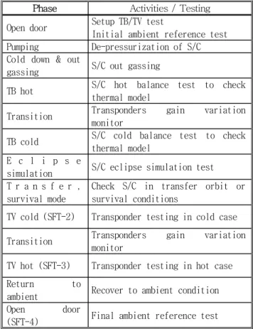
Phase Activities / Testing Open door Setup TB/TV test
Initial ambient reference test Pumping De-pressurization of S/C Cold down & out
gassing S/C out gassing
TB hot S/C hot balance test to check thermal model
Transition Transponders gain variation monitor
TB cold S/C cold balance test to check thermal model
E c l i p s e
simulation S/C eclipse simulation test T r a n s f e r ,
survival mode
Check S/C in transfer orbit or survival conditions
TV cold (SFT-2) Transponder testing in cold case Transition Transponders gain variation
monitor
TV hot (SFT-3) Transponder testing in hot case
Return to
ambient Recover to ambient condition
Open door
(SFT-4) Final ambient reference test Figure 4: CATR Test Configuration and Radiation pattern
Table 2: CATR test result at Tx
Table 3: CATR test result at Rx
3.4 Ka Payload Environment Test 3.4.1 Vibration Test of Ka band payload
The sine vibration test was conducted in x, y and z-axes with the flight level. A low level vibration survey was conducted to measure natural frequency.
Accelerometers were attached on the Ka band payload to measure dynamic response. The maximum deviations of the natural frequency between pre and post low-level sine survey are within 5% in all axes.
The vibration test results show that no structural degradation or fracture occurs during test.
3.4.2 Acoustic Test of Ka band payload
Acoustic test was conducted to simulate launch load condition. Low level acoustic surveys were conducted before and after test to detect any structural failure or degradation of Ka band payload.
There is no frequency difference between pre and post low-level results. The acoustic test results show that the Ka band payload(reflector) has enough design margin to withstand the applied acoustic vibration loads.
3.4.3 Thermal Vacuum Test
3.4.3.1 Test parameter and procedure
Thermal Balance (TB) and Thermal Vacuum (TV) test was performed in KARI facility. The Ka-band EGSE was installed outside of chamber and long waveguide were connected between EGSE and Ka-band Transponder for RF performance measurements during the thermal cycling. Thermal profile is as follows.
Figure 5: Thermal Vacuum Test of COMS
3.4.3.2 Test result of TV
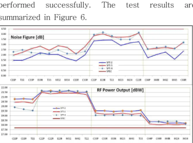
Thermal Vacuum test for transponder RF performance (SFT-2, SFT-3, and SFT-4) was
performed successfully. The test results are summarized in Figure 6.
Figure 6: Thermal Vacuum Test Results for MainParameters of Each Transponder Channel
3.4.4 EMI/EMC Compatibility Test
The RF auto-compatibility test was performed in large EMC chamber at Intespace in Toulouse. The purpose of the test is to check RF interference level between payloads in COMS in normal operation condition. The threshold level was -65dBc as in-band spurious specification. The result shows no spurious level over -65dBc when TCR and MODCS were powered on. After RF auto-compatibility test, two test carriers were injected on the Ka-band transponder to measure 55th PIM level. The result shows no PIM signal on 55th and the other order PIMs also. As a result, auto-compatibility test and PIM test were successfully completed. The test setup for RF auto-compatibility and PIM test is shown in Figure 7.
Ka-band Transpobder Diplexer
TX W/G RX W/G
Test bench (EGSE) TX signal
OMUX Anechoic Chamber
IF/LNA
Stimulus signal Response signal
Figure 7: RF auto-compatibility and PIM test setup
During the launch campaign, Ka-band payload health check was performed as a final TM/TC functional checking. All Ka-band TM/TC functions were verified. The health check parameters are as
following.
o Discrete TM/TC check
- RF switch position TM/TC functional checking - Active equipment on/off TM/TC and analog TM
(current, voltage, temp.) display checking o LSSB TM/TC check
- Channel Amp modes(FGM/ALC), output level (Gain/Level) functional checking
- MSM TM/TC functional checking
Ⅳ. In Orbit Test
1 Launch
COMS on board Ka Payload was successfully launched at Kourou in French Guyane at 27th Jun.
2010. (Korean Time). It was stationed at GEO 128.2E.
2 Ka Payload IOT
2.1 Test parameter and procedure
Ka-band Payload IOT was performed in two parts, Antenna Pattern Measurements (APM) and payload RF Performance Measurements. Ka payload configuration change was done by KARI SOC (Satellite Operation Center) according to ETRI request and Ka-band telemetry was forwarded to IOT operation center at ETRI. The overall Ka Payload IOT configuration is shown in Figure 8.
Figure 8: Ka-band IOT configuration
□ APM (Antenna Pattern Measuremnet)
Three Ka-band antenna beam patterns were measured at the first phase of IOT. When S/C was slewing, each beam Antenna Pattern was measured at IOT station. The APM information is as follows.
o APM beams: SK/NK and China beams
Parameter Spec.
Value
De-pointing Value S. Korea beam
center
Azimuth -0.09 -0.02
Elevation 5.75 0.06
N. Korea beam center
Azimuth -0.19 -0.06
Elevation 6.20 -0.03 o Cross cuts for each beams: ± 1o range o Ch. Amp modes
- ALC mode for TX pattern - FGM mode for RX pattern o S/C slewing speed: 0.2 o /min.
o Time synchronization between IOT station and SOC
□ Payload RF Performance Measurement
After completing APM, RF performance measurements for Transponder channels are performed. The Test parameters of P/L IOT are as following.
o IPFD/EIRP (Transfer characteristics) o Amplitude vs. Frequency Response (AFR) o Frequency conversion characteristics o Payload G/T
o FGM function o ALC function
2.2 Test Result
Table 4 shows the APM results for the South Korea beam and the North Korea beam. The de-pointing angles are within acceptable range and no ADTM adjustments are necessary.
Table 4: APM test results
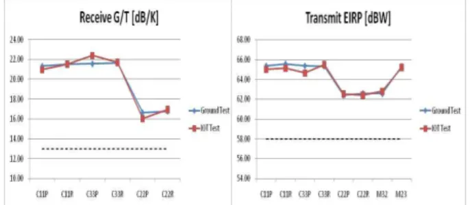
Figure 9 shows the major RF performance of Ka band payload evaluated from IOT measurement results. IOT measurement for RF performance of the South Korea channels and the North Korea channels are performed successfully and all performance are consistent with the ground test results.
Figure 9: IOT RF performance results
Ⅴ. Applications
As completing IOT and verifying excellent status of Ka Payload, it is to apply the various areas. It is to use Ka frequency transmission experiment including rain attenuation and modeling study, and RF performance verification over lifetime of domestic built Ka Payload system. It is also to apply Test-bed for new developed technology such as VSAT terminal and service including UHDTV and 3DTV transmission by domestic University, Industry and Institutes. It is to apply for public services such as natural disaster prevention / recovery services.
Ⅵ. Conclusion
Ka payload composed of on board switching transponder and multi-horn antenna was developed successfully by ETRI in cooperation with local companies.
Around 80 % of Ka payload equipments was designed, manufactured and tested by ETRI and domestic companies, and integration & test of transponder and antenna was successfully completed by local technology. Local technology of Ka Payload development was perfectly verified as a result of in orbit test which shows compliant to ground test result.
Ka Payload developed by ETRI is to operate normally, and to apply several areas including public services.
Reference
[1] SP Lee, “Development of Satellite Communication System for COMS”, Proceedings of APSCC pp.
71-96, 2004.
[2] JH Lee, JH Kim, SP Lee, HJ Lee, “Multi-beam Satellite Antenna Design”, IEEE International Symposium on Antenna and Propagation and USNC/URSI National Radio Science Meeting, Session 84, July 2004.
[3] JS Choi, YD Lee, SP Lee, “Development of Ka band Multibeam Antenna”, 13th Ka and Broadband Communications Conference, K000055, 2007.
[4] JS Choi, YD Lee, SP Lee,“CATR Test for Ka band Multi-beam Antenna”, 26thInternational Communications Satellite Systems Conference
(ICSSC), June 2008, AIAA 2008-5511)
저 자 이 성 팔 (LEE, Seong Pal) 정회원 1990년 6월:미 뉴욕공대 전자공학 박사 1980년 4월∼현재:한국전자통신연구원 책임연구원
<관심분야> 위성시스템, 위성통신시스템, 통신탑재체
조 진 호 (JO, Jin Ho) 정회원
1988년 2월:충남대학교 전자공학 석사 1989년 6월∼현재:한국전자통신연구원 책임연구원
<관심분야> 통신위성 중계기 시험, 위성 궤도 내 시험
유 문 희 (YOU, Moon Hee) 정회원
1990년 8월:한양대학교 전자통신공학 석사
1990년 7월∼현재:한국전자통신연구원 책임연구원
<관심분야> 위성통신시스템, 통신탑재체
최 장 섭 (CHOI, Jang Sup) 정회원
1988년 2월:KAIST 기계공학과 석사 2010년 2월:충남대학교 기계공학과 박사 수료
2000년 10월∼현재:한국전자통신연구원 책임연구원
<관심분야> 위성통신시스템, 통신탑재체, 위성AIT