Design and Analysis of a Power Control and Monitoring System for Buoy
Jin-Seok Oh†․Kwan-Jun Jo1
(Received October 8, 2009 ; Revised November 24, 2009 ; Accepted November 25, 2009)
Abstract:This paper describes a study for the buoy which should be operated by a stand-alone power system. The field of this study is related to a power system operated by two batteries which depends on the load power. The fluctuation of the voltages makes the life cycle of the battery shorten. The control algorithm has been proposed for reducing the voltage pulsation of the battery by operation strategy according to using purpose such as main or sub power supply system. The power system with battery is separated two parts and this has been proved through a simulation and a sea experiment. In order for the experiment to use a wireless monitoring system has been installed in buoy. This paper shows an excellent test result of wireless monitoring system for buoy.
Key words:Buoy, Hybrid Generation, Power Control, Monitoring, Power System
†Corresponding Author(Korea Maritime University, Dept, of Mechatronics, E-mail : [email protected], Tel : 051-410-4283)
1 Korea Maritime University, Dept, of Mechatronics
1. Introduction
A buoy, which is a traffic facility for maritime safety, is operated to help ships to sail safely in the difficult condition to identify a sea sight, such as nighttime and foggy and therefore a stabilized power supply is required in rough sea condition.
At present, most of the buoy is using the stand-alone power system employing the photovoltaic cells. However, the PV module system can cause the lack of the power because the power quantity from the photovoltaic cells can be lower in a rainy condition which is affected by a typhoon and a heavy rainy season as seasonal and climatic factors. To solve these problems the research on a hybrid generation system combined with the photovoltaic is in progress.
In case of a buoy, there are marine
signal lights and communication systems as main loads and Anti-Fouling System (AFS) and dummy System as auxiliary loads. The quantity of power generation at sea depends on the weather condition.
Therefore, in accordance with the quantity of power generation when over produced the power should be consumed by using the auxiliary load systems and when the lack of the power the power source of the battery should be protected with blocking the auxiliary power. The life cycle of the battery decreases depending on the number of charging or discharging and the variation of battery voltages getting bigger. In order to enhance this point, a charging control system with centering to the battery voltages is important. At present, in case of the buoy at sea, it is observed by going to the sea directly with
some intervals to identify the condition of the voltages and generated power of the battery. Mostly, on account of going out when the weather is benign the number of charging and discharging and voltage variation rate cannot be noticed[1-3].
This work proposes a hybrid generation power system that consists of the battery divided into two parts such as main and sub. In order to find out whether the control characteristics of the proposed system can reduce the pulsation of the battery voltages the fluctuation of the battery voltages has been observed by installing a wireless communication system which enables the buoy to be observed at sea.
2. Hybrid Power System for Buoy
The hybrid buoy in this study consists of the photovoltaic cells and wave energy.
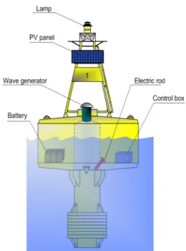
The wave energy generation for the buoy is designed by Oscillating Water Column (OWC) type. OWC is suitable for the buoy like the resonance dependant on the movement of the buoy. Figure 1 shows the hybrid buoy which is designed with solar and wave generation system.
The power generated by the PV module and wave generator is charged to a battery and that charged power is used for marine signal lights, AFS system and auxiliary loads. The photovoltaic and wave power generation have mutually complementary characteristics in the weather environment. When the weather is fine the photovoltaic generation produces a lot of power and when a wave height is high the wave generation
produces a lot of power. In case of cloudy and rainy days, a wave height has the characteristic to be high for strong wind.
The wave power is generated in accordance with the movement of water.
This movement is affected by the resistance inside OWC and water flows into water column.
Figure 1: Hybrid buoy(Solar & Wave)
2.1 Power Control System
The structure of the hybrid buoy consists of battery, marine signal lights and auxiliary loads. Figure2 (a) shows the power control system for hybrid buoy. The battery is charged with a produced power and the charged power is supplied to marine signal lights and auxiliary loads.
The battery voltage is changed with a weather condition, and the battery's life is decided by the cycle of charging and discharging in battery.
To extend the battery's life in buoy, the power system is divided into two parts such as sub (65Ah) and main (150Ah) battery for power supply. The sub and main batteries can be charged respectively.
(a) Original hybrid power control system
(b) New hybrid power control system Figure 2: Hybrid power control system
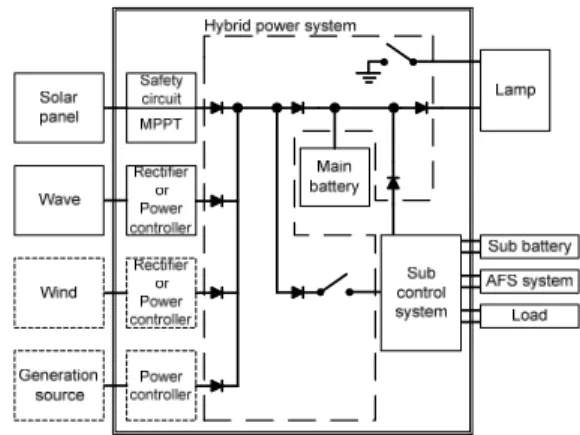
Figure3 shows a hybrid power system configuration which is operated with the battery charging and load conditions.
Figure 3: Hybrid power system
The hybrid power system can be charged the main and sub batteries, respectively, and the battery's power is supplied to the load according to power condition. This hybrid power system operates with a various control and switching algorithm such as reverse voltage blocking, multi-switching algorithm, etc.
2.2 Power Control Algorithm
Hybrid power controller is the most important to maintain a constant voltage of the battery because it was remodelled.
Lead-acid batteries used in marine facilities, and is a 12V 200Ah capacity.
The battery voltage has to keep about ± 10% of the rated voltage. Battery discharge voltage can be calculated with Equation (1).
·
·
(1)
Where, is the rated battery voltage,
is 10% lower than the rated voltage, which is the discharged battery voltage, is the capacity degradation of lead acid
battery. [Ah] is the capacity, is the charging current. [V/min] is the voltage variation of battery when battery is charged or discharged. The loss of battery's internal resistance is ignored in this equation.
The relationship between production power and consumption power is shown in Figure 2. is total production power,
is photovoltaic generation power,
is wave generation power, is power line loss of production power. is charging power of main battery, is the power consumption of marine signal lights. is the sub battery charging power in 2-battery system and sub load discharge power in 1-battery system, respectively. The sub load power when the 2-battery system discharged from the sub battery.
(2)
The charge-discharge current with main battery charge-discharge power and battery voltage are unknown. The Equation (3) shows the relationship between charge power and charge- discharge current. is power consumption of the system. is battery voltage, is unit time per minute.
(3)
Buoy on sea has not enough power for operating equipments because it is operated by the stand-alone power
system. However, the consumption power in buoy is a lower than production power when the buoy designed. Figure 4 shows the power control algorithm of main and sub battery. The battery voltage is controlled according to battery voltage.
Also, the switching strategy is operated with battery voltage and operation condition for load[4-7].
(a) Voltage of main battery
(b) Voltage of sub battery Figure 4 Power control algorithm
The control algorithm for arbitrary generation power and consumption power in buoy was assumed for simulation.
Figure 5 shows the simulation results by control algorithm. The simulation results show that the battery voltage is changed by weather condition and consumption power of operation equipment in buoy[8-10].
Figure 5: Simulation results
3. Monitoring System for Buoy
Power system for buoy can be checked by monitoring system. Specially, the battery status always has to detect in real time for buoy's duty. For this purpose, the monitoring system for buoy is designed with a wireless communication system. The monitoring system is shown in Figure 6.
Figure 6: Monitoring system for sea test
It is consisted of RF modem, repeater, monitoring PC, and program. The monitoring system for buoy can be operated with low-cost wireless modem, no communication charge because buoy has to operate for long time. This system installed two PV modules and one Wells turbine, the capacity is 80W and 30W, respectively.
4. Experiments and Analysis
The power system influences the operation efficiency of battery. In this paper, 1 or 2 battery type for power system in buoy is installed, and it is operated with the hybrid power generation system. Figure 7 shows the experiment buoy, repeater, and monitoring screen.
Figure 7: Experiment buoys(L), repeater(C) and monitoring screen(R)
Figure 8: Voltage regulation of 1-battery type
Figure 9: Voltage regulation of 2-battery type In 1-battery type buoy, the battery voltage is changed in Figure 8. Figure 9
shows the battery voltage of 2 battery type in buoy. The voltage variation of 2-battery type is lower than 1-battery type in power system. Also, the monitoring data can be achieved with the designed wireless communication system.
5. Conclusion
This paper is described the hybrid power system with battery in buoy. The power system of 2-battery type can be operated with reducing voltage variation of the battery. Specially, the hybrid power generation system for buoy extracts power from solar and wave according to weather condition for a whole day. The power system of 2-battery type is more efficiency in the hybrid power generation system.
This system is expected to be operational and cost effectiveness. In addition, the monitoring system with RF modem is low-cost monitoring system which life-cycle research for battery is needed through various tests.
Acknowledgement
This paper is based on 'A development of hybrid power generation system for ocean facility' supported by Ministry of Land, Transport and Maritime Affairs.
This paper is based on 'Development of the remote condition monitoring system of building integrated Wind-Photovoltaic hybrid energy systems via wireless telecommunication networks.' supported by British Council PMI 2 Connect - Research Co-operation Award.
References
[1] Kwan-Jun Jo, Hee-Han Yoo, Seung-Gi Gug and Jin-Seok Oh, “Design and Analysis of Power System for Buoy”, Journal of Korean Navigation and Port Research, vol. 31, no. 3, pp.
229-233, 2007.
[2] Kwan-Jun Jo, Sung-Young Jung, Soo-Young Bae, Ji-Young Lee and Jin-Seok Oh, “A Study on the MPPT Algorithm for Buoy”, Journal of the Korean Society of Marine Engineering, vol. 33, no. 4, pp. 588-594, 2009.
[3] Eckhard Karden, “Using Low- Frequency Impedance Spectroscopy for Characterization, Monitoring, and Modeling of Industrial Batteries”, Doctoral Thesis at RWTH Aachen University (ISEA), Shaker Verlag, 2002.
[4] D. Feder, T. Croda, K. Champlin and M. Hlavac, “Field and laboratory studies to assess the state of health of valve regulated lead acid batteries”, Proceedings of the 14th International Telecommunications Energy Conference, pp. 218-233, 1992.
[5] M. Hlavac, and D. Feder, “VRLA Battery Conductance Monitoring”, Proceedings of the 18th International Telecommunications Energy Conference, pp. 632-639, 1996.
[6] M. Kniventon, and A. I. Harrison,
“Impedance/ conductance measurements as an aid to determining replacement strategy”, Proceedings of the 20th international Telecommunications Energy Conference, pp. 297-301, 1998.
[7] Larminie, James and Dicks, Andrew,
“Fuel Cell Systems Explained”, 2nd edition, John Wiley & Sons, 2003.
[8] IEEE Recommended Practice for Maintenance, “Testing and Replacement of Valve Regulated Lead Acid (VRLA) Battery for Stationary Application”, IEEE Std 1188-1996, 1996.
[9] Jin-Seok Oh, “Research of DC-DC converter for ocean buoy”, Journal of Korean Navigation and Port Research, vol. 31, no. 10, pp. 8391-844, 2007.
[10] Jin-Seok Oh, Jun-Ho Kwak, Soo-Young Bae, Sung-Young Jung and Ji-Young Lee, “Generation characteristic of WEC for buoy”, Journal of the Korean Society of Marine Engineering, vol.
32, no. 8, pp. 1123-1128, 2008.
Author Profile
Jin-Seok Oh
He was born in Kyung -Nam Korea, in 1978. He received the B.E. degree in Marine Engineering from Korea Maritime University in 1983. Since 1983, He has been with the Zodiac(England Company) including early 4years of System Engineer. He received the M.E. and Ph. D.
degrees from Korea Maritime University, Busan ,Korea in 1989 and 1996, respectively. Also, he received the Ph.D.
degree from Kyushu University, Fukuoka, Japan in 2009. He had been with the Agency for Defense Development(ADD) as a re searcher from 1989 to 1992. From 1992 to 1996, he was an Assistant Professor in the Department of Industrial Safety Engineering at Yangsan College. In 1996, he joined the Division of Mechatronics Engineering at Korea Maritime University. His research interests include a renewable energy system, electrical drive system, ship control system and PC-based Control applications.
Kwan-Jun Jo
He is a PhD student at the Mechatronics Engineering at Korea Maritime University.
He has the master degree in Mechatronics Engineering and a bachelor of Mechatronics Engineering from korea maritime University. His main research interests include renewable energy systems, electrical drive system, and PC-based control application.
![Figure 5 shows the simulation results by control algorithm. The simulation results show that the battery voltage is changed by weather condition and consumption power of operation equipment in buoy[8-10].](https://thumb-ap.123doks.com/thumbv2/123dokinfo/4842304.283313/4.786.406.705.329.731/figure-simulation-algorithm-simulation-condition-consumption-operation-equipment.webp)

