1.
서 론발전소에서 생산된 전기를 안전하게 수용가에 공급 하기 위해 분전반(distributing board)을 사용하며, 또는 이것을 배전반이라고도 부른다. 자가용 변전소의 배전 반을 전면에서 보면 고압 주회로의 차단기를 개폐하는 조작레버, 저압 주회로의 개폐기, 전압계, 전류계, 전력 계, 적산전력계, 와전류계전기 등이 있다. 배전반의 형 식에는 개방형과 폐쇄형이 있는데 개방형은 뒷면에 전 기배선 , 스위치, 단자 등이 노출되어 있다. 폐쇄형은 금 속함 내부에 대부분 수납되어 있어서 외부에서 보이는 것은 최소한의 계기 , 조작 버튼 등이다. 개방형의 경우 는 유닛(unit)의 치수가 표준화되어 있기 때문에 변전 소 등의 규모에 따라서 유닛의 수를 정한다 .
그리고 선박이나 철도차량용, 공작기계용, 호이스트
장비용 또는 폭발성이 있는 대기에서의 사용 등과 같은 특수 사용 상태 하에서의 사용을 위해 설계된 분전반 , 가정용으로 사용되도록 설계된 분전반에 적용한다 . 전 동기 기동장치 , 퓨즈개폐기, 전자장비 등과 같이 그것 들의 관련 규격에 따르는 개별 장치 및 독립적인 구성 품에는 적용하지 않는다 . 한국산업규격 KS C 61439-1 에서 제시하는 저압용 분전반의 규격은 정격전압 교류 1,000 V 이하, 직류 1,500 V 이하 등의 범위 내에서 적 용된다 . 그리고 한국전기공업협동조합(KEMC)의 분전 반에 대한 기준은 KS C IEC 61493-1, SPS-KEMC 2102-610 등이 있다
1-4).
그리고 분전반을 통해서 전력을 공급하는 전기설비 는 관련 규정을 준수하여 제작하고 적절한 관리 및 검 사를 병행하면 분전반에 의한 사고의 발생 가능성이 거의 없다. 그러나 부적절한 부하의 사용, 초과된 용량
스마트 분전반 제작을 위한 작업 공정도 개발에 관한 연구
이병설․최충석
† 전주대학교 소방안전공학과(2017. 2. 22. 접수 / 2017. 5. 25. 수정 / 2017. 6. 7. 채택)
A Study on the Development of a Work Operation Process Chart for Smart Distribution Board Fabrication
Byung-Seol Lee․Chung-Seog Choi
† Department of Fire Safety Engineering, Jeonju University(Received February 22, 2017 /Revised May 25, 2017 / Accepted June 7, 2017)
Abstract : This study presented the strength of the materials and parts for smart distribution board fabrication, and developed a work
operation process chart for smart distribution board fabrication. This work operation process chart for smart distribution board fabrication complied with SPS-KEMC regulations, and the applicable range and object are less than 1,000 V and 1,000 Hz for the AC distribution board and less than 1,500 V for the DC distribution board. The power supply is 3 phase 4 wires (3Φ 4W), divided into a single phase circuit and a 3 phase circuit. In addition, the circuit was configured so that the leakage current flowing through the distribution line of the load could be monitored in real time by using the sensor module installed at the rear end of the circuit breaker. Therefore, the administrator can easily find the risk factor of the load since engineer can check the leakage current of each distribution line. In addition, if a leakage current greater than standard value flows, it is possible to generate an alarm against a short circuit and cut off the leakage current. The work operation process chart for the smart distribution board fabrication consists of the following steps: raw and subsidiary materials, sheet metal work, tube making, welding, painting, busbar fabrication, assembly and wiring, product inspection, shipment, etc. Moreover, symbols, △, ▽, O, ⇒, etc. were used according to the type of work and work progress so that workers can easily understand the progress of the work.Key Words : work operation process chart, smart distribution board, leakage current, circuit breaker, busbar
†Corresponding Author : Chung-Seog Choi, Tel : +82-63-220-3119, E-mail : [email protected]
Department of Fire Safety Engineering, Jeonju University, 303 Cheonjam-ro, Wansan-gu, Jeonju 55069, Korea
의 연결, 부적절한 관리 등으로 전기설비 사고 및 전기 화재의 발생 가능성은 상대적으로 높아진다. 분전반에 서 발생되는 사고는 접촉(속) 불량, 누설전류 및 과부 하 등이 대부분이다 . 특히, 전선로에 적은 누설전류가 흐를 때 초기에는 큰 문제가 없으나 장시간 사용하고 설비의 노화가 시작되어 열화(劣化)가 진행되면 필연 적으로 전기설비 사고를 유발시켜 재해로 이어지는 것 이다
5-10).
따라서 본 연구에서는 저압 분전반 제작을 위한 재 료와 부품의 강도 특성을 분석하는데 있다. 또한, 개발 된 분전반은 실시간으로 누설전류를 검출하여 경보하 고 차단할 수 있는 기능이 탑재되어 있으므로 새로운 작업 공정도를 제시할 필요가 있다 . 그리고 기존 설비 를 제작한 경험이 있는 기술자들이 쉽게 인식할 수 있 도록 단계별로 제시하여 작업의 생산성 및 신뢰성 향 상에 기여하고자 한다.
2.
개발된 분전반의 구조개발된 분전반은 SPS-KEMC를 준용하였으며, 적용 범위 및 대상은 1,000 V 이하, 1,000 Hz 이하인 교류 정 격 전압이다. 또는 1,500 V 이하의 직류 정격 전압을 갖는 저압 분전반이다. 또한, 더 높은 주파수의 제어 및 전력 설비를 포함하고 있는 배전반에도 적용되며 , 폐쇄함의 설치여부에 관계없이 고정형 또는 이동형 분 전반에 적용된다.
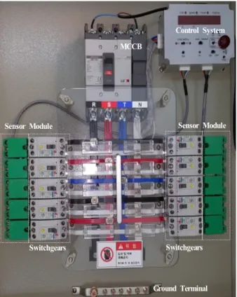
Fig. 1은 개발된 10회로 저압 분전반의 실체 사진을 나타낸 것이다. 상부에 배선용차단기(MCCB)를 설치하 여 주전원이 유입되도록 배치하였고, 부하측의 배선은 부스바 (bus bar)를 이용하여 색 배선(R, S, T, N)하였다.
그리고 부스바를 사용하여 좌우측으로 병렬 분기하여 다양한 부하를 효과적으로 사용할 수 있도록 구성하였 다. 또한, 분기된 각각의 차단기 부하측에 센서 모듈 (sensor module)을 설치하여 부하 전선로에서 발생되는 누전전류의 크기를 실시간 측정할 수 있어서 우측 상 단에 설치된 시스템으로 실시간 그 상태를 알 수 있는 제품이다.
Fig. 2는 개발된 분전반의 구성도를 개략적으로 나 타낸 것이다. 분전반은 3상 4선식(3Φ 4W)로 전원을 공 급할 수 있고, 단상 회로와 3상 회로 등으로 구분되어 있다. 그리고 부하에 연결된 각각의 부하 상태를 상시 감시할 수 있어서 누전 경보 및 차단이 가능하다. 즉, 전원 각각의 회로 상태를 관리자 또는 관계자가 실시 간으로 확인이 가능하므로 효율적인 전원 관리가 가능 한 특징이 있다. 그러므로 전선로에서 발생되는 누설
전류의 변화를 이력 관리 할 수 있다. 또한, 사용자의 요구에 따라 다양한 형태로 병렬 분기할 수 있는 구조 이므로 구매자의 요구에 효과적으로 대응할 수 있는
제품이다
5-10).
MCCB
Control System
Ground Terminal
Sensor Module Sensor Module
Switchgears Switchgears
Fig. 1. Stereoscopic photography of the developed distribution panel.
1
3 2
14 30
17 18 19
Display MCCB
15(3Φ)
16(3Φ)
31(3Φ)
32(3Φ)
R S T N
ZCT CT
Controller
switches Sensor
module
Fig. 2. Schematic diagram of the developed distribution panel.
Table 1은 개발된 분전반에 적용된 재료와 부품의 강도를 나타낸 것으로 KS C IEC 61439-1을 적용하였 다. 또한, 개발된 분전반은 내식성, 절연 재료의 특성, 자외선 복사의 내성 , 인양, 기계적 충격 등의 항목에 적합하도록 설계되었다
2-4).
옥내에 설치되는 분전반은 IEC 60068-2-30, 60068-2-11 을 적용한다. 그리고 내습성은 40±3℃, 습도 95 %에서 24 시간 6회 실시하도로 되어 있다. 또한, 염무는 35±2
℃에서 24시간 7회 실시하도록 되어 있다. 옥외에 설치 되는 분전반은 IEC 60068-2-30, 60068-2-11을 적용한다.
내습성은 옥내용과 동일하고 단지 5회를 실시하도록 되 어 있다 . 염무 시험 역시 동일한 조건에서 성능을 유지할 수 있어야 하며 , 단지 2회를 실시하도록 되어 있다.
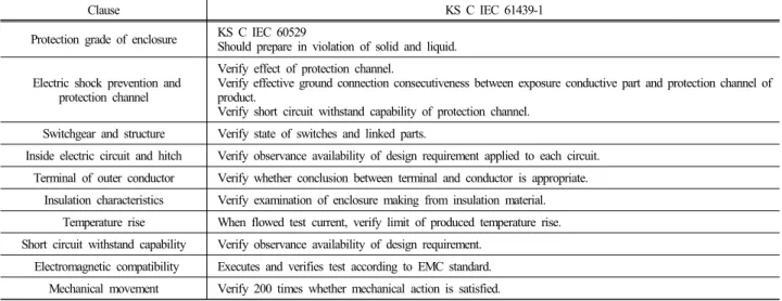
Table 2는 KS C IEC 61439-1에 제시되어 있는 분전 반 외함의 검증 방법을 나타낸 것이다. 외함의 보호 등
급, 감전 방지와 보호회로, 개폐장치와 구성품, 내부 전 기 회로와 연결부 , 외부 도체의 단자, 절연 특성, 온도 상승 , 단락 내력, 전자파 적합성, 기계적 동작 등을 분 석하였다. 감전 방지와 보호 회로는 조립체의 노출 도 전부와 보호회로 사이의 효과적인 접지 연속성과 단락 내력을 검증해야 하는 것으로 되어 있다 . 또한, 내부 전기 회로와 연결부는 주회로 , 보조회로, 비피복 도체 와 절연 도체, 주회로와 보조 회로의 도체 식별 등의 설계 요구 사항의 준수 여부를 검증한다
2-4).
3.
개발된 분전반의 작업 공정도작업자는 일정한 성능과 품질을 유지하고 있는 제품 을 지속적으로 생산할 수 있어야 한다. 즉, 우수한 품 질 유지 및 안정적 제품 생산을 위해서 작업 공정도가 Table 1. Material of low voltage distributing board and strength of parts
Clause KS C IEC 61439-1
Corrosion resistance
indoor IEC 60068-2-30, 60068-2-11
① moisture proof; 40 ± 3℃, humidity; 95 %, 24 hr., 6 times
② salt water; 35 ± 2℃, 24 hr., 7 times
outdoor IEC 60068-2-30, 60068-2-11
① moisture proof; 40 ± 3℃, humidity; 95 %, 24 hr., 5 times
② salt water; 35 ± 2℃, 24 hr., 2 times
Characteristics of insulating material
IEC 60068-2-2
① Thermal tests of enclosure is 168 hours, and recovery time is 96 hours.
Temperature enforces in 70℃.
②Introspection examination of insulation material carries out in 125 ± 2℃. Other segment sets up in 70 ± 2℃.
Ultraviolet radiation of immunity ISO 4892-2 A
temperature; 65 ± 3℃, humidity; 65 ± 5 %, water service; 5 min., drying periods; 5 min., 100 times
Salvage
Raises 1 ± 0.1 m at position of stationary state, and executes inheritance.
Keeps product while blow 30minutes in 1 ± 0.1 m, and lifts 1 ± 0.1 m height after 2th repeat. And 10±0.5 m moves horizontality.
Execute in heritance 3 times in dead lock, each sequence achieves with in 1 minute.
Mechanical impact KS C IEC 62262
Table 2. Verification method of enclosure used to low voltage distributing board
Clause KS C IEC 61439-1
Protection grade of enclosure KS C IEC 60529
Should prepare in violation of solid and liquid.
Electric shock prevention and protection channel
Verify effect of protection channel.
Verify effective ground connection consecutiveness between exposure conductive part and protection channel of product.
Verify short circuit withstand capability of protection channel.
Switchgear and structure Verify state of switches and linked parts.
Inside electric circuit and hitch Verify observance availability of design requirement applied to each circuit.
Terminal of outer conductor Verify whether conclusion between terminal and conductor is appropriate.
Insulation characteristics Verify examination of enclosure making from insulation material.
Temperature rise When flowed test current, verify limit of produced temperature rise.
Short circuit withstand capability Verify observance availability of design requirement.
Electromagnetic compatibility Executes and verifies test according to EMC standard.
Mechanical movement Verify 200 times whether mechanical action is satisfied.
필요하고, 그 내용을 작업자들에게 충분히 이해시켜야 한다. Table 3은 개발된 분전반의 공정도를 상세하게 제시한 것으로 원부자재, 판금 가공, 제관 가공, 용접 가공, 도장 가공, 부스바 가공, 조립 및 배선, 제품 검 사, 출하 단계 등으로 구성되어 있다.
분전반 제작의 공정도는 작업의 유형과 진행 정도에 따라 △, , ▽, O, ⇒ 등의 기호를 사용하여 작업자가 작업의 진행 정도를 쉽게 이해하고 , 시각적인 인지가 가
능하도록 병기하였다 . 공정 관리는 항목, 방법, 담당, 기 록 등으로 세분화했으며 , 각각의 항에 수행해야 할 내용 을 기호 문자로 제시하였다 . 그리고 각 단계별 제작된 제품은 각 단계에 부합하는 관련 규격을 근거로 검사를 실시하였다. 또한, 제품의 생산성 및 효율성 등을 고려하 여 외주되는 부품 및 기기 등은 수시로 제품의 성능을 확인함으로써 제품이 완성되었을 때 오작동 , 접속 불량, 오결선 등의 발생을 근원적으로 차단되도록 관리하였다 . Table 3. Operation process chart for cabinet board manufacture with leakage current alarm and interception function
No. Processname Process
chart Job sheet Installation Process control Inspection
Standard Note Clause Method Duty Record Clause Method Record
1 Raw materials
△ warehousingMaterial
Receiving inspection
Ruler Weighing machine
Naked eye Clause Standard Inspection
report
HMQI-502- 1~161-
▽ Preservation
2 Sheet metal working
O Manufacture Cutting machine Folding machine
press
Shape Size Pressure
Current Frequently Worker Process
move card HMQI406
-1-2 Itself &
outside order processing
Interim
inspection Ruler
Vernier calipers Shape
Size Angle Sampling inspection Process
move card HMQI-502- 2-1
⇒ Transport
3 Board working
O Manufacture Cutting machine
Drill shape
Pressure Frequently Worker Process
move card HMQI406
-1-3 Itself &
outside order processing
Interim
inspection Ruler
vernier calipers Shape
Size Sampling inspection Process
move card HMQI-502- 2-2
⇒ Preservation
4 Welding processing
O Manufacture Welding machine File
Shape Current State
Welding rod Frequently Worker Process
move card HMQI406
-1-4 Itself &
outside order processing
Interim inspection
Ruler Weighing machine
Naked eye
Shape Current State Welding rod
Sampling inspection Process
move card HMQI-502- 2-3
⇒ Preservation
5 Painting processing
O Painting Compressor
Air ejector Drying furnace
Shape Temperature
Time Color Frequently Worker Process
move card HMQI406
-1-5 Itself &
outside order processing
Interim
inspection Plating thickness instrument
Shape Thickness
Color Adhesion
Sampling inspection Process
move card HMQI-502- 2-4
⇒ Preservation
6 Busbar processing
O Manufacture Wire forming Machine of busbar Mold spanner
Shape Size Thickness
Adhesion Frequently Worker Process
move card HMQI406
-1-6 Itself processing
Interim inspection
Ruler Naked eye Vernier calipers
Shape Size Thickness Adhesion
Sampling inspection Process
move card HMQI-502- 2-5 frequently
⇒ Preservation
7 Assembly and wiring
O connectionWiring Wire forming Machine of busbar
Wiring Instrument
Conductor Frequently Worker Process
move card HMQI406
-1-7 Itself assembly
Interim inspection
Clamp meter Ruler Insulation resistance meter
Wiring Adhesion
Busbar
Sampling inspection Process
move card HMQI-502- 2-6 frequently
⇒ Preservation
8 Product
inspection Product inspection
Withstand voltage meter Circuit tester
Shape Size Structure Sequence Withstand
voltage
Sampling inspection Inspection
report HMQI502-3 -1
9 Shipment ▽ Delivery HMQP -
410
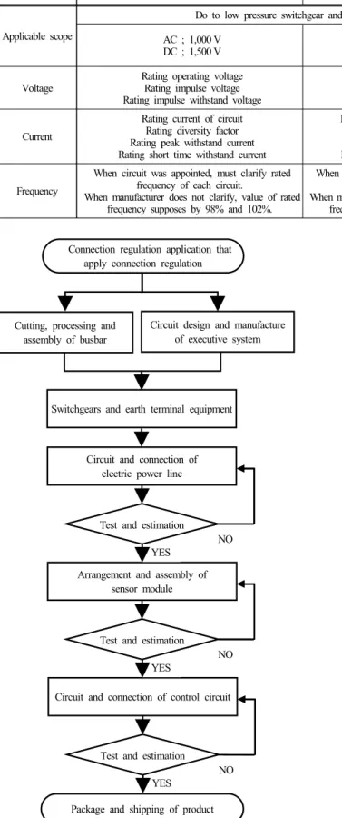
Connection regulation application that apply connection regulation
Cutting, processing and assembly of busbar
Package and shipping of product Switchgears and earth terminal equipment
Circuit design and manufacture of executive system
Arrangement and assembly of sensor module
Circuit and connection of control circuit Circuit and connection of
electric power line
YES Test and estimation
NO
YES Test and estimation
NO
YES Test and estimation
NO
Fig. 3. Process of manufacture of panels with leakage current detection and alarm functions.
Fig. 3은 실시간으로 누설전류를 검출하여 경보하고 차단할 수 있는 기능이 탑재된 분전반의 제작 과정을 나타낸 것이다 . 기존 분전반 제작 경험이 있는 숙련된 기술자가 작업을 효율적으로 수행하고 , 각 단계별 검 사를 실시할 수 있도록 흐름도 형식으로 제시한 것이 다. 즉, Table 3에서 제시된 작업공정도에 따라 각각의 작업이 완료되면 제시된 흐름도를 준수하여 조립 및 검사 등을 실시하여 출하도록 하였다.
Table 4는 저압 분전반의 전기적 특성에 대해 KS C IEC 61439-1, SPS-KEMC 2102-610 및 JSIA-300을 비교한 것이다 . 즉, 개발된 분전반의 시험 및 평가를 객관적으로 입증하기 위해 관련 규정을 준수하였다. 일반 산업 현 장에서 사용되는 저안 분전반의 항목은 적용 범위, 전 압, 전류, 주파수 등을 대상으로 실시하였다. 또한, 단 위 기능반의 특정 사용 조건에 따른 추가 요구는 별도 로 조건을 지정한다
2-4).
이상의 분석 내용에서 알 수 있듯이 누전 경보 및 차 단 기능이 탑재된 분전반 제작을 위한 공정도가 개발됨 에 따라 기존 분전반을 제작한 경험이 있는 기술자들이 특별한 교육 및 훈련이 없이도 제품의 생산이 가능할 것으로 판단된다. 또한, 개발된 분전반이 건축물에 설 치된다면 전선로에서 발생되는 누설전류의 상태를 실 시간 경보 및 차단할 수 있어서 전기설비사고 , 전기화 재 및 감전사고 등을 예방할 수 있어서 경제적 손실과 사회적 비용을 저감할 수 있을 것으로 기대된다 .
4.
결 론본 연구에서는 저압 분전반 제작을 위한 재료와 부 품의 강도 특성을 분석하였다 . 또한, 스마트 분전반 제 작을 위한 공정도를 개발하여 다음과 같은 결과를 얻 었다 .
Table 4. Electrical properties of low voltage distributing board
Clause KS C IEC 61439-1 SPS-KEMC 2102-610 JSIA-300
Applicable scope
Do to low pressure switchgear and control device.
AC ; 600 V, 50 Hz, 60 Hz DC ; 250 V
AC ; 1,000 V DC ; 1,500 V
AC ; 1,000 V 1,000 Hz DC ; 1,500 V
Voltage Rating operating voltage
Rating impulse voltage Rating impulse withstand voltage
Rating using voltage Rating insulation voltage
Rating impulse withstand voltage -
Current
Rating current of circuit Rating diversity factor Rating peak withstand current Rating short time withstand current
Rating short time withstand current Rating peak withstand current Rating using short circuit current Rating melting short circuit current
-
Frequency
When circuit was appointed, must clarify rated frequency of each circuit.
When manufacturer does not clarify, value of rated frequency supposes by 98% and 102%.
When circuit was appointed, must clarify rated frequency of each circuit.
When manufacturer does not clarify, value of rated frequency supposes by 98% and 102%.
-