Strain Transmission Characteristics of Packaged Fiber Bragg Grating Sensors for Structural Health Monitoring
Sung-In Cho*, Seung-Jae Yoo*, Eun-Ho Kim*, In Lee*✝, Il-Bum Kwon** and Dong-Jin Yoon**
Abstract Fiber Bragg grating(FBG) sensor arrays can be used to monitor the mechanical behavior of the large composite structures such as wind turbine rotor blades and aircrafts. However, brittle FBG sensors, especially multiplexed FBG sensors are easily damaged when they are installed in the flexible structures. As a protection of brittle FBG sensors, epoxy packaged FBG sensors have been presented in this paper. Finite element analysis and experiments were performed to evaluate the effects of adhesives, packaging materials and the bonding layer thickness on the strain transmission. Two types of epoxy were used for packaging FBG sensors and the sensor probes were attached with various bonding layer thickness. It was observed that thin bonding layer with high elastic modulus ratio of the adhesive to packaging provided good strain transmission. However, the strain transmission was significantly decreased when elastic modulus of the adhesive was much lower than the packaged FBG sensor probe’s one.
Keywords: Fiber Bragg Grating(FBG), Wind Turbine Rotor Blades, Health Monitoring, Packaging, Bonding Layer
Received: March 25, 2010, Revised: May 11, 2010, Accepted: June 10, 2010. *Division of Aerospace Engineering, KAIST, 373-1 Guseong-dong, Yuseong-gu, Daejeon 305-701, Korea, **Center for Safety Measurement, Korea Research Institute of Standards and Science 1 Doryong-dong, Yuseong-gu, Daejeon 305-340, Korea, ✝ Corresponding Author: [email protected]
Journal of the Korean Society for Nondestructive Testing Vol. 30, No. 3 (2010. 6)
1. Introduction
Fiber Bragg grating(FBG) sensor arrays can be used to monitor the mechanical behavior of large structures such as wind turbine rotor blades or aircrafts (Zayas et al., 2007). However, FBG sensors made on bare fibers are easily damaged when they are installed in the large structures. In this regard, packaging and installation techniques for the FBG sensors are needed to be developed.
Recently, some novel techniques for packaging FBG sensors were developed and compared with the bare FBG sensors. Lin et al. (2005) developed three types of packaging methods using steel tube, epoxy glue and nickel. Wnuk et al. (2005) studied the effects of two bonding compounds to mount the optical fiber sensors
onto the metal shim on the bonding strength, strain transfer and environmental protection.
Effects of bonding layer on strain transmission of FBG sensor were also studied and developed recently.
Lin et al. (2005) also reported the effects of elastic modulus and the thickness of adhesive on strain transmission using FEM simulation.
However, they did not give experimental results and the results were limited only for two cases.
Cheng (2005) developed an analytical model of strain transmission to FBG sensor bonded onto the substrate with bonding material. Li (2009) validated strain transmission is influenced by stiffness of the substrate and the sensor as well as the bonding layer thickness. However, the model would not be valid when the sensor
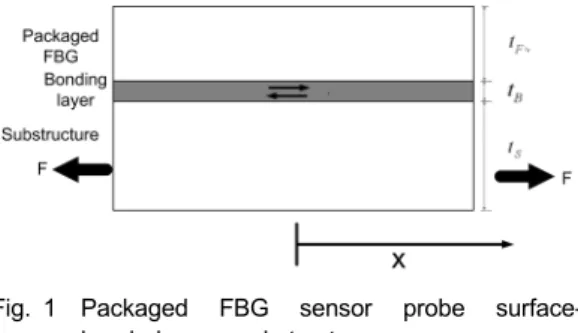
Fig. 1 Packaged FBG sensor probe surface- bonded on a substructure
probes and the bonding layer are thick.
This paper describes a procedure for packaging an FBG sensor and effects of bonding layer for the strain measurement. Finite element analysis and experiments were performed to evaluate the effects of stiffness ratio of the adhesives to packaging materials and the thickness of bonding layer on strain transmission.
Three types of epoxy adhesives and two types of packaging epoxy with different elastic moduli were used to characterize the strain transmission of the bonding layer.
2. Principles of FBG Sensors
The introduction of fiber optic sensors offer a lot of advantages. Especially, the FBG sensors have a lot of distinct advantages (Lin et al., 2005) such as linear response to strain, remote sensing, absolute measurement and ease of multiplexing. FBG sensors are made by illuminating the core of a suitable optical fiber with a spatially varying pattern of intense UV laser lights that have sufficient energy to break the highly stable silicon-oxygen bonds (Ciang et al., 2008). This will increase its refractive index slightly. A periodic spatial variation in the intensity of UV light, caused by phase mask placed over the fiber, gives rise to a corresponding periodic variation in the refractive index of the fiber (Doyle, 2003). If different phase masks are used, gratings with different Bragg wavelength can be written. Thus, it is possible to write different unique gratings into one fiber. This is called wavelength division multiplexing technique, which makes it possible to distinguish the different sensing signals and relate them to the designated locations.
3. Strain Analysis of Bonding Layer
Cheng et al. (2005) suggested an analytical model of strain transmission from substrate to FBG sensor probe. In his model, an elastic
bonding layer of finite thickness was assumed to be present between the sensor probe and the substructure, leading to a classic shear lag solution. Assume a packaged FBG sensor probe with the diameter of are bonded with the bonding layer thickness of onto the substructure of diameter, as shown in Fig. 1.
When the substructure is subjected to an external force F, the strain of the substructure is transferred through the bonding layer to the sensor probe. The strain distributions of the sensor probe and the substructure are derived in the references (Cheng et al., 2005; Li et al., 2009). The strain measured by the sensor can be represented by eqn. (1).
(1)Where and are strain of the substructure and the sensor probe, is shear lag parameter, and is stiffness ratio of the adhesive to the packaging. Shear lag parameter and stiffness ratio are defined by the following equations.
,
,
(2)
Where is the nondimensional coordinate, is shear modulus and is length of the bonding layer. The first bracketed term of the eqn. (1) can be neglected when the thickness and the elastic modulus of the substructure are much
(a) (b)
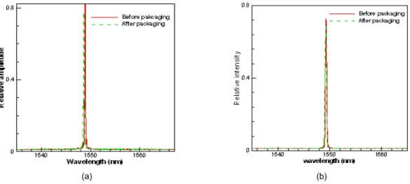
Fig. 2 Comparison of FBG reflectivity between bare FBG sensor and packaged FBG sensor; (a) Wavelength change of type 1 packaged FBG sensor, (b) Wavelength change of type 2 packaged FBG sensor
Table 1 Characteristics of the epoxy
Type Epoxy Use Elastic modulus(MPa)
cured at 20 ℃
Elastic modulus(MPa) cured at 80 ℃
1 AR-16 Packaging 1950 -
2 Duralco 4535 Packaging 464 -
a MOS 7 Adhesive 1.28 11.73
b BOND-IT 7040 Adhesive 1960 2499
c Duralco 4535 Adhesive 464 481
higher than the sensor probe’s. Therefore, the strain transferred from the substructure to the sensor probe is dependent on shear lag parameter, .
4. Experiments
4.1 FBG Sensor Packaging
Two types of epoxy are used to protect the brittle bare fiber from external environments.
Packaging the FBG sensor with epoxy has distinct advantages, such as its low cost, easy fabrication process and high water resistant. And epoxy also has low elastic modulus compared to the optical fiber sensors, so that it is easy to obtain high strain transmission from adhesive layer (Cheng et al., 2005).
However, the epoxy packaging process can induce residual stress to the FBG sensor. High
residual stress can broaden the FBG gratings.
Residual stress can induce localized non-uniform strain along the entire grating length. Then, it affects the magnitude of the FBG reflectivity.
Since the change of Bragg wavelength can reduce the sensitivity of the FBG sensors (Wnuk, 2005), it is needed to consider the effect of the epoxy packaging on FBG sensor reflectivity. For the experiments, packaged FBG sensors with the size of 70×3×3 mm were fabricated, and two types of epoxy were used for packaging.
Characteristics of type '1' and type '2' epoxy are shown in Table 1. In this process, FBG sensors with 10 mm grating length were used. Fig. 2.
shows the change of FBG reflectivity caused by curing process of each packaging epoxy. The changes of Bragg wavelength were 0.3 and 0.2 nm, respectively. They show each packaging have little effect on the FBG reflectivity.
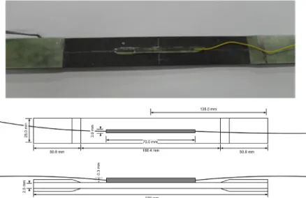
Fig. 3 Photograph and schematics of the specimens with packaged FBG sensor probe attached 4.2 Experimental Setup
Glass/epoxy fabric (glass fabric prepreg 224 E/black, Hankuk Fiber Glass Co., Ltd.) composite specimens were made for tensile tests.
Glass/epoxy fabric composite material is widely used for wind turbine blades because of its low cost, high mechanical properties and high electric resistance. The specimens were used for the host structure and the packaged FBG sensor probes were installed onto the specimens. Three types of epoxy adhesives and two types of packaging epoxy with different elastic moduli were used to characterize the strain transmission between the sensor probes and the host materials. Elastic moduli of the composite specimen and epoxy were obtained based on ASTM D-3039 and ASTM D-638 specification, respectively.
Conventional resistant type strain gauges were used to measure the increment of strain and the experiments were done by using universal testing machine Instron 4482. Epoxy adhesives were cured at both room temperature(20 ℃) and high temperature(80 ℃) since epoxy could have different mechanical properties depending on curing condition.
Elastic modulus of the composite specimen was 45.76 (± 2.59) GPa. The elastic moduli of
the packaging epoxy and the epoxy adhesives are shown in Table 1. Packaging epoxy type ‘1’
showed much higher elastic modulus compared to type ‘2’ epoxy. Adhesive type ‘a’ had the lowest elastic modulus and adhesive type ‘b’ had the highest elastic modulus compared to others.
Adhesive type ‘a’ and ‘b’ showed the increase of elastic modulus depending on curing temperature.
Especially, adhesive type ‘a’ showed dramatic increase of elastic modulus. Therefore, adhesive type ‘a’ and ‘b’ were cured at both 20 ℃ and 80 ℃ to attach the sensor probes. On the other hand, adhesive type ‘c’ showed slight change of elastic modulus and this adhesive was cured at 20 ℃ to attach the sensor probes.
The size of the composite specimens and the packaged FBG sensor probes were 270×25×2.5 mm and 70×3×3 mm, respectively.
Two types of sensor probes were attached onto the upper surface of the specimens using three types of adhesives with 0.5 mm, 0.3 mm and 0.1 mm of the bonding layer thickness. Each bonding layer thickness were adjusted using modified mold which were used to fabricate packaged FBG sensor probes. Adhesives were filled in the modified mold with the sensor probes maintaining desired bonding layer thickness. After bonding the sensor probes,
(a)
(b)
Fig. 5 Strain transmission classified by the elastic modulus ratio of adhesives to the packaging (0.5 mm bonding thickness); (a and b) Strain transmission depending on elastic modulus ratio of adhesive to the packaging
bonding layer thickness was measured by comparing the thickness among composite specimens, FBG sensor probes and the specimens with the sensor probes attached. The manufactured specimens have 10% error of desired thickness.
The specimen with the packaged FBG sensor probe is shown in Fig. 3. The specimens with the sensor probe were tested by universal testing machine Instron 4482. Axial load was gradually increased and corresponding wavelength shift of the FBG sensor was measured by IS7000 (fiber Bragg grating interrogation system, Fiberpro, Inc.) with 2 pm strain resolution. Conventional resistant type strain gauges were attached onto the rear side of the specimen for the comparison with the strain obtained from the packaged FBG sensor.
5. FEM Simulation
Glass/epoxy composite specimen with packaged FBG sensor probe was modeled by 3-D hex elements using MSC/PATRAN &
MSC/NASTRAN as shown in Fig. 4. The model consists of 4 parts; specimen, adhesive, epoxy packaging and optical fiber. They were assumed to be perfectly bonded with each other. Static analysis was performed to calculate the axial strain of the optical fiber sensor embedded in the epoxy packaging.
Fig. 4 Specimen modeling using MSC/PATRAN &
MSC/NASTRAN
6. Results
Fig. 5 shows the resultant strain during tensile tests measured by packaged FBG sensor probes and strain gauges. As mentioned before, two types of packaged FBG sensor probes were attached using three types of adhesives with 0.5 mm, 0.3 mm and 0.1 mm of the bonding layer thickness, and these figures show the case of 0.5 mm bonding thickness. The strain measured by type 1 packaged FBG sensor was shown in Fig. 5(a) and the strain measured by type 2 packaged FBG sensor was shown in Fig.
5(b). Each case is classified by the elastic modulus ratio of adhesives to packaging. In these figures, the elastic modulus ratio of adhesives to packaging is represented as
.
(a)
(b)
(c)
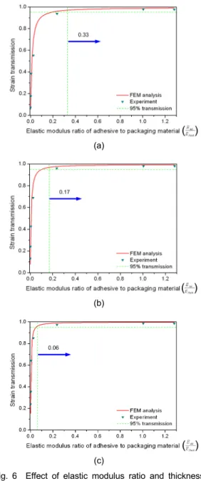
Fig. 6 Effect of elastic modulus ratio and thickness on strain transmission; (a) Adhesive layer 0.5 mm thick, (b) Adhesive layer 0.3 mm thick, (c) Adhesive layer 0.1 mm thick Fig. 6 shows the strain transmission of the
bonding layer depending on the elastic modulus ratio of the adhesives to the packaging. The experimental results were compared with the FEM simulation and the analytic solution using eqn. (3) which is derived from Li (2009). The strain transmission of the bonding layer was calculated by comparing the strain measured by the packaged FBG sensors and the strain gauges. Fig. 6. shows that good agreement is obtained between FEM simulation and tensile experiments. However, the results show slight difference between the analytic solution and the FEM simulation, especially when the bonding layer is thick. The strain transmission was significantly affected by elastic modulus ratio of the adhesives to the packaging. Especially, for a case with the adhesive ‘a’ with 0.5 mm thickness whose elastic modulus is much lower than the one of packaging epoxy, strain transmission was only 7.2%. However, it can provide good protection for large deformation measurements. Large composite structures, such as wind turbine blade can support more than strain level of 8000 (Paquette and Veers, 2007) in some regions, and FBG sensor can support strain level of 6000 (Doyle, 2003).
In this case, bonding layer which show low strain transmission can be used to protect the FBG sensor by compensating strain transmission of the bonding layer.
Strain transmission was increased by increasing the elastic modulus ratio of the adhesive to the packaging or decreasing the thickness of bonding layer. To obtain the strain transmission more than 95% with 0.5 mm, 0.3 mm and 0.1 mm of the bonding layer thickness, the elastic modulus ratio of the adhesive to the packaging need to be larger than 0.33, 0.17 and 0.06, respectively. However, adhesive with high elastic modulus could be suffered from debonding problem when compressive load is applied (Ecke and Schroeder, 2008). Thin bonding layer could also cause debonding problem (Papanikos et al.,
2007). Therefore, to obtain the required strain transmission protecting from debonding problems, elastic modulus of the adhesive and the bonding layer thickness should be compromised.
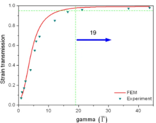
Fig. 7. shows the effect of shear lag parameter, which is given in eqn. (4) on the strain transmission. This figure shows dramatic increase of the strain transmission depending on
Fig. 7 Effect of gamma () on strain transmission
the shear lag parameter. From this results, shear lag parameter can be used to obtain required strain transmission.
7. Discussions
Finite element analysis and tensile experiments with composite specimens have been carried out to characterize the strain transmission depending on elastic modulus ratio of the adhesives to the packaging and the thickness of the bonding layer. Thin bonding layer with high elastic modulus ratio of the adhesive to packaging provided good strain transmission.
However, the strain transmission was significantly decreased when elastic modulus of the adhesives was much lower than packaged FBG sensor probe's. In this case, the bonding layer which shows low strain transmission can be used to protect the FBG sensor by compensating strain transmission of the bonding layer.
Elastic modulus of the adhesive and the bonding layer thickness should be compromised to avoid debonding problem. To obtain the strain transmission of more than 95% for 0.5 mm, 0.3 mm and 0.1 mm of bonding layer thickness, the elastic modulus ratio of the adhesive to packaging need to be larger than 0.33, 0.17 and 0.06, respectively. It was also shown that shear lag parameter need to be larger than 19 to obtain 95% of the strain
transmission. Therefore, to obtain the required strain transmission, thickness of bonding layer and the sensor probe, and elastic modulus ratio of the adhesives to the packaging should be selected based on the shear lag parameter.
Acknowledgements
This research was supported by New &
Renewable Energy R&D Program under the Korea Ministry of Knowledge Economy(MKE) (2010-N-WD08-P-01) and by a grant(07-02) from Aviation Safety R&D Center Program funded by Ministry of Land, Transport and Maritime Affairs of Korean government.
References
Cheng, C. C., Lo, Y. L., Pun, B. S., Chang, Y.
M. and Li, W. Y. (2005) An Investigation of Bonding-Layer Characteristics of Substrate- Bonded Fiber Bragg Grating, Journal of Lightwave Technology, Vol. 23, No. 11, pp.
3907-3915
Ciang, C. C., Lee, J. R. and Bang, H. J. (2008) Structural Health Monitoring for a Wind Turbine System: A Review of Damage Detection Methods, Measurement Science & Technology, Vol. 19, No. 12
Doyle, C. (2003) Fiber Bragg Grating Sensors – an Introduction to Bragg Gratings and Interrogation Techniques, Smart Fibers Ltd.
Report
Ecke, W. and Schroeder, K. (2008) Fiber Bragg Grating Sensor System for Operational Load Monitoring of Wind Turbine Blades, Proc. of SPIE, Vol. 6933, No. 18
Kang, L. H. (2004) Estimation of Structural Deformation Using Fiber Optic Bragg Grating Sensor Array, Master’s Thesis, KAIST
Kim, W. S. (2003) Damage Detection Techniques of Composite Laminates with Embedded FBG Sensors, Master’s Thesis, Department of Aerospace Engineering KAIST
Li, W. Y., Cheng, C. C. and Lo, Y. L. (2009) Investigation of Strain Transmission of Surface-Bonded FBGs Used as Strain Sensors, Sensors and Actuators, Vol. 149, No. 2, pp.
201-207
Lin, Y. B., Chang, K. C., Chern, J. C. and Wang, L. A. (2005) Packaging Methods of Fiber-Bragg Grating Sensors in Civil Structure Applications, IEEE Sensors Journal, Vol. 5, No.
3, pp. 419-424
Micron Optics, (2005) Optical Fiber Sensors Guide, pp. 6-7
Papanikos, P., Tserpes, K. I. and Pantelakis, S.
(2007) Initiation and Progression of Composite Patch Debonding in Adhesively Repaired Cracked Metallic Sheets, Composite Structures, Vol. 81, No. 2, pp. 303-311
Paquette, J. A. and Veers, P. S. (2007) Increased Strength in Wind Turbine Blades through Innovative Structural Design, Sandia National Laboratories
Wnuk, V. P. (2005) Process for Mounting and Packaging of Fiber Bragg Grating Strain Sensors for Use in Harsh Environment Applications, Proceedings of SPIE, Vol. 5758, No. 6, pp.
46-53
Zayas, J. R., Roach, D. P., Rumsey, M. A., Allen, W. R. and Horsley, D. A. (2007) Low-Cost Fiber Bragg Grating Interrogation System for In-Situ Assessment of Structures, Proceedings of SPIE Vol. 6529, No. 110